SETRONIC VERONA ILIA ERHSO712 User manual


EN 54-12 Costruito in conformità con la Norma Europea
Built in compliance with European standard
Erfüllt die Europäische Norm
Certificazione CE
CE Certification
CE Zertifizierung
0786-CPR-20925
Riferimenti normativi - Reference regulations - Vorschriften normen
SETRONIC Verona
Prodotto secondo la norma di rispetto ambientale
Manufactured in accordance with the regulations and
respect for the environment as in
Produktion im Einklang mit allen gültigen Umweltschutzbestimmungen
2002/96/CE
01111 Certificazione russa
Russian certificate
Russisches Zertifikat
II
Certificazione VdS
VdS certification
VdS Zertifizierung
n° G209195
EN 54-17 Costruito in conformità con la Norma Europea
Built in compliance with European standard
Erfüllt die Europäische Norm

ENGLISH MANUAL


CONTENTS
mod. ERHSO712 (Transmitter-Receiver version)
Basic characteristics.....................................................51
Product characteristics...................................................51
System description......................................................52
Working Principle.......................................................53
Calibration and assembly procedure........................................54
Main calibration procedures...............................................55
Procedure for further adjustment...........................................56
Technical features ......................................................57
Setting of diaphragm ....................................................58
mod. ERRHSO712 (Reflection version)
Basic characteristics.....................................................60
Product characteristics...................................................60
System description......................................................61
Working Principle.......................................................62
Calibration and assembly procedure........................................63
Main calibration procedures...............................................64
Procedure for further adjustment...........................................65
Technical features ......................................................66
Setting of diaphragm ....................................................67
CONTROLLER mod. CSRLS / mod. CSRLS - Dust
Display message and programming step. . . . . . . . . . . . . . . . . . . . . . . . . . . . . . . . . . . . . 69
1. Menu access protect by password.....................................69
2. Sensibility Setting..................................................69
3. Modify of Transmitter level and check of the signal level received . . . . . . . . . . . . . . . . 70
4. Auto calibration of Transmitter level . . . . . . . . . . . . . . . . . . . . . . . . . . . . . . . . . . . . 71
5. Alarm Auto test....................................................73
6. Alarm Reset.......................................................74
7. System Configuration...............................................74
8. Modify of the password for menu access . . . . . . . . . . . . . . . . . . . . . . . . . . . . . . . . 76
9. Display messages for events .........................................76
Choose the right cable...................................................78
Caution for installation...................................................78
Parameter of simple «autonomous» isolator . . . . . . . . . . . . . . . . . . . . . . . . . . . . . . . . . . 78
Socket circuit with protection..............................................79
Dip-switch for the address of the smoke beam detectors . . . . . . . . . . . . . . . . . . . . . . . . 79
Typical connection to a conventional control panel with end line resistor . . . . . . . . . . . . 80
Typical connection to an addresable control panel . . . . . . . . . . . . . . . . . . . . . . . . . . . . . 81
Connection to MRS reset module ..........................................82
Typical of possible connections............................................83
BEAM DETECTOR ILIA MAINTENANCE AND CONTROL 86
ADDITIONAL CONTROLS 86
TROUBLE SHOOTING 87
ENGLISHENGLISH
Mod. MII rev. 01 SETRONIC Verona 49

HIGH SENSITIVITY
LINEAR BEAM DETECTOR
MODEL ERHS0712
ENGLISH
50 Mod. MII rev. 01
SETRONIC Verona

TRANSMITTER - RECEIVER VERSION
Basic characteristics
Ÿ Detector: Project, Technology, Design and Production fully made in Italy
Ÿ Suitable for use in all civil and industrial premises
Ÿ Very easy to install and program
Ÿ Low cost for mounting, cabling and maintenance
Ÿ The Detector can be installed horizontally or vertically and can work at any angle
Ÿ Micrometric adjustment for alignment
Ÿ Integrated diaphragm with a wide range of adjustment
Ÿ Control Unit for programming, calibration and performing of remote test on line
beam detectors.
Ø Basic configuration for two Detectors even of different types
Transmitter/Receiver or Reflection
Ø Expansion board for connection up to 3 to 8 detectors and line loop closure
(optional)
Ø Ground level installation for the Control Unit
Ø Alarm and Fault outputs can be programmed for each individual detector
Ø Operational access to keyboard protected by password
Ø Control Unit or Control Panel reset facility or by the MRS module
Ÿ Base
Ø Plug-in base to detector connection
Ø Base complete with back up board short circuit isolator to ensure continued
work even after a short circuit
Ÿ Special Allen Key suitable for mechanical alignment, diaphragm regulation, unhook of
detector base and open/close of control unit
Product characteristics
Ÿ Standard EN 54-12
Ÿ Protection rating IP65 (Transmitter Unit, Receiver Unit and Controller Unit)
Ÿ RoHS Compatibility
Ÿ Operating distance 10 ÷ 200 m for Tx/Rx model
Ÿ Width of cover up to 15 m
Ÿ Connections to 4 serial line conductor RS485
Ÿ Local and remote maintenance request
Ÿ Automatic threshold compensation
Ÿ Angle misalignment ± 1degree max
Ÿ Complete directional stability over time
Ÿ Sensitivity adjustable and selectable over a wide range, using the control unit model CSRLS
Ÿ Automatic reset of detector after break in infrared beam
Ÿ Self tester for RS485 communication
Ÿ Fault relay output delayed up to 90 seconds
Ÿ Power supply 24 V DC
Ÿ It is available, on request, the Control unit model CSRLS in the DUST version, with special
thresholds applicable in critical environments characterised by high levels of dust, steam or
other vapours
ENGLISH
Mod. MII rev. 01 SETRONIC Verona 51

SYSTEM DESCRIPTION
The ILIA MODEL ERHS0712 detector consists of a Transmitter Unit, a Receiver
Unit and a Beam Controller Unit for programming, setting and testing. The Beam
Controller Unit is used to remotely manage the detector or detectors in the field
using a single line. The Beam Controller Unit is put at a place on ground level from
where the detector can be controlled without having to climb up to the detector, as
regards all normal operations. The Beam Controller Unit is made of plastic, has a
keyboard for programming and a backlight 16x2 display.
By entering a password of 4 digits you can program the system from ground level to
determine the detector's signal level, to check environmental disturbances, to set
the required thresholds based on these and to check the alarm threshold; the
default password FFFF can be changed by the programmer by following the
instructions in the remote programming menu.
The system configuration menu becomes available when you just touch any of
the 5 buttons on the keyboard and by then entering the default password FFFF on
the first programming session, customising the password from then on (the
password can be reset if lost or forgotten by use of the beam controller Unit reset
hardware).
The Beam Controller Unit electronic base permits direct connection of two detector
units; by means of an expansion circuit (SMLS), it is able to pilot up to 8 detectors
connected together and a connection with two stub lines or by a closed loop. With
this second typology the system continue proper working even if the cables are cut
or in the case of a short circuit by the protection circuit inserted in each single
detector. There are also programmable relay contacts in the Unit for each
individual detector connected. These relays can have their polarity reversed with
the use of the software and permit the transmission to a single central unit of the
individual alarm, fault and maintenance request signals. Any breakdown in
communication between Beam Controller Unit and the detectors connected to it
will be immediately signalled by the simultaneous flashing of the yellow Led and
the green Led on the Transmitter and the Receiver, as well as being indicated on
the display of the Beam Controller Unit itself.
The controller is also available in the Dust version (CSRLS-2-DUST), suited to
very difficult environments, using special VdS certified software that enables the
detection threshold to be calculated up to the maximum limit permitted by standard
EN54-12 without losing the principal characteristics of this model: producing early
detection in any environment.
ILIA with the Dust version controller has already come successfully through lab and
environmental real scale fire testing; these tests have shown that the model's
detection ability assures early alarm in any environment, overcoming unfavourable
conditions that could give rise to false or to fault alarms.
ILIA with the Dust version controller is thus a highly reliable response to the needs
of problematic environments with dust, steam, fumes or particular working
processes where other technologies are unable to assure the required security
and accurate and precise detection.
ENGLISH
52 Mod. MII rev. 01
SETRONIC Verona

The working voltage of the equipment is between 12 and 24 Volts without switching
(± 20%). The Transmitter Unit emits a beam of modulated infrared light at 1 KHz in
the form of a cone which crosses the space under surveillance to reach the
Receiver Unit. As the modulated infrared crosses the environment under
surveillance, it collects along its path all information that could suggest the start of a
fire. The events that intervene between Transmitter and Receiver affect the
infrared carrier, alternatively optically modulating it in frequency and in amplitude.
WORKING PRINCIPLE
The Receiver Unit demodulating from the infrared received the information that is
optically gathered, transforms each symptom of a possible fire into corresponding
electrical signals referable to “smoke”.
Such signals are electronically assessed by means of a special algorithm local to
the Receiver Unit, and are transmitted to the Beam Controller Unit. All the units
have a microcontroller that carries out a full scan of the working mode, i.e. not only
of the alarm, but also of faults, blinding and maintenance requests. The messages
are clearly given on the display and repeated by the four leds on the Unit, as well as
with the local led's on every individual piece of equipment. A message on the
display will indicate the type of event and the detector number.
NOTE: The Dip-Switch must always be used during installation to
determine the detector address number, also if is there only
one detector. In the loop configuration the Dip-Switch 4 must
stay in the «OFF» position.
The connection of one or more detectors is with leads of a minimum cross-section,
2
in accordance with current regulations, of 0.5 mm . For the type of cable to use
please refer to current regulations; it is not necessary to use shielded cable.
The detection of the start of a fire will mean information is sent from the field
(detector) to the Beam Controller Unit which will in turn send an alarm signal to a
central control unit. System resetting is possible both from the Beam Controller
with a dedicated command or from the central control unit or closing, by a normally
open contact, the two terminal blocks of the MRS module.
The Beam Controller Unit can be used to set the blinding fault relay switching delay
for every individual detector, for times from 0 to 90 seconds.
The Receiving Unit (RX) has an internal diaphragm that means it is possible,
following the instruction to mechanically set for the use of a diaphragm filter, to
solve environmental problems in particular architectural situation where there are
awkward reflections or the optical beam must work in limited spaces or get dirty
before the starting up.
ENGLISH
Mod. MII rev. 01 SETRONIC Verona 53

ASSEMBLY PROCEDURE
NOTE 1: Use the SETRONIC "Allen Key" for the opening and the closing of the detector and the
mechanical alignment of the equipment.
NOTE 2: to grant that the socket maintain the IP65 protection degree, be sure that i twill be fixed in flat
surface. If this it is not possible use a bracket or a swivel.
1. Fix the socket connection of the detector and carry out the wiring of the line (power supply and serial line).
2. Set the address of the detector between 1 and 8 consequently using the Dip-Switch according to the table on page
79. This operation must be done on both unit, so to have the same address on Transmitter and Receiver.
It's suggested to make these operation before the fixing of the socket.
NOTE: The Dip-Switch 4 must be set to ON only in the last socket connected to the line open. It must
also be set with a single detector.
3. Insert the connector plug on the bottom of the detector into the socket until you hear a "click", then lock the unit to
the socket by rotating the hooks with the appropriate Allen key and guide it to the paired device from the opposite.
4. Repeat above operations for all the detectors installed. Verify that the Transmitter and Receiver pair have the
same address.
CONNECTIONS CHECK BEFORE START-UP
(to be made only with the loop configuration)
1. Disconnect the two terminals "power output" and "serial line" of the main module and the two terminals "power
output" and "serial line B" of the expansion module.
2. With a multimeter measure the resistance on the wires, between the positive output of the first power supply and
the positive of the second supply line. Also measure the resistance, always on the wires, between the negative
output of the first power supply and the negative of the second supply line.
3. Both resistance values read, must be less than 100 Ω
4. Reconnect the cables and make sure that the clamps are inserted securely.
CALIBRATION PROCEDURE
1. Power the system via the controller and set the number of detectors connected and the configuration of connection
to serial line. The controller also allows the use of the two serials in an independent manner, as if they were two
separate lines open. In this case, the addresses remain the same from set 1 to 8, but you set the end of the line
(Dip-Switch 4 to ON) of both the last detector.
2. At this point the green led of the two detector units should switch on and you must switch controller, a short flash
confirms the continuous scanning of the line. If on the units is present the condition of led flashing green and yellow
with flashes of about 2 sec., means that there is no serial communication (check the wiring for possible errors or
inversions) or incorrect configuration of the switch address. In such a case please verify: the cabling for possible
mistakes or inversions, the wrong configuration of the address switches (double same number) or the wrong
number of connected detectors (menu system set-up).
3. Point the Transmitter through the Allen key adjustment in order to obtain the led blinking yellow.
4. Starting i.e. from the left to move the unit slowly until the yellow led stops flashing. Then rotate the unit to the right
(the yellow led starts to flash again). Count how many turns of the key are made to obtain the yellow led off to the
opposite side. Reposition the center of movement found by dividing in half the number of revolutions counted. The
yellow led continues to blink.
5. Do the same for the vertical axis.
6. Point the Receiver following the same steps 3, 4, 5.
7. Perform the calibration by the ground controller to follow the menu <Auto Adjust>.
8. Now cover the Transmitter Unit or Receiver Unit with a card or opaque object. When you cover the Unit check that
the yellow led remains continuously on.
ENGLISH
54 Mod. MII rev. 01
SETRONIC Verona

MAIN CALIBRATION PROCEDURES
1. E nter menu
ž from the main screen, press OK;
ž enter the password, using the direction buttons „‚ƒ; press OK;
2. Set up detection lines
ž press „ or ƒ until you get to < System Setup >; press OK;
ž press or ‚ to edit the number of the detection lines; press OK;
ž press or ‚ change the delay time for fault outputs; press OK;
ž press or ‚ change the configuration of fault outputs; press OK;
ž press or ‚ to set the <Com Line> configuration; press OK;
ž press OK to skip debug function.
3. First calibration of the detection lines (after mechanical adjustment of the
detectors)
ž press „ or ƒ until you get to < AUTO Adjust. >; press OK;
ž press or ‚ to change the number of the detection line to be worked on; press OK;
ž wait until the TX value stabilises and press OK;
ž the value of the RX must be about 100% (see note at pag. 72)
ž press OK to confirm the setting.
4. Calibration of detection lines (with the barriers already previously installed)
ž press „ or ƒ until you get to < AUTO Adjust. >; press OK;
ž press or ‚ to change the number of the detection line to be worked on; press OK;
ž wait until the TX value stabilises and press OK;
ž the value of the RX must be about 100% (see note at pag. 72)
ž press OK to confirm the setting.
5. Adjustment of detection line sensitivity
ž press „ or ƒ until you get to < sensitivity >; press OK;
ž press or ‚ to change the number of the detection line to be worked on; press OK;
ž read the Detec value to quantify environmental disturbances;
ž press or ‚ to change the smoke threshold value (the value of the highest
disturbance value seen by Detec shall be less than the threshold setted) ; wait for
2 sec and press OK;
ž read the Detec value to quantify environmental disturbances;
ž press to ‚ change the fire threshold value (the value of the highest
disturbance value seen by Detec shall be less than the threshold setted);
ž wait for 2 sec and press OK to confirm the setting.
ENGLISH
Mod. MII rev. 01 SETRONIC Verona 55

PROCEDURE FOR FURTHER ADJUSTMENT
ž1. Enter menu
ž from the main screen, press OK;
ž enter the password, using the direction buttons „‚ƒ; press OK;
2. Checking the signal and manual adjustment of detection lines
ž press „ orƒ until you get to < adjustment >; press OK;
ž press or ‚ to edit the number of the detection lines; press OK;
ž read the RX signal; it must normally be about 100% (see note at pag. 72);
ž press or ‚ to change the TX value;
ž press OK to confirm the setting.
ž
3. Alarm simulation for detection lines
ž press „ or ƒ until you get to < Alarm Test >; press OK;
ž press or ‚ to edit the number of the detection lines; press OK;
ž press OK to start the alarm testing;
ž wait for the barrier alarm;
ž press OK to reset the barriers (for details about menu see pag. 73);
4. Reset the detection lines alarm
ž press „ or ƒ until you get to < Reset Alarm >; press OK;
ž press OK to reset the alarm;
žIt is possible to reset the alarm also by the MRS module, if connected
(see pag. 82)
5. Change the password for access to the menu
ž press „ or ƒ until you get to <Change password; press OK;
ž enter the new password, using the direction buttons „‚ƒ;
ž press OK to confirm the setting.
ENGLISH
56 Mod. MII rev. 01
SETRONIC Verona

TECHNICAL FEATURES
ILIA High Sensitivity Transmitter / Receiver Linear Beam Detector model ERHS0712
Working temperature -20°/+65° C
Storage temperature -20°/+70° C
Electromagnetic disturbance EMC test up to 30 Volt/m (VdS protocol)
Power supply 2 4V DC ± 20%
Cable type minimum section of 0,5 mm² with 4 wires
type CEI 20-22 (see details on page 78)
Maximum cable length max 1200 m from Control Unit to line detectors
Maximum permitted cover 1600 m² per detector
Width cover max 15 meters
Operating distance from 10 to 200 meters
Angle misalignment ± 1 degree max
Detector protection rating IP65
RAL Colour 5004 black blue
1013 oyster white (on request)
With material PPE+PS HI
RAL Colour 9005 jet black
With material PPE+PS «Noryl» Flame Class V0 selfextinghuishing
Size 162x145x193 mm
Weight Tx Unit 735g, Rx Unit 775g
Beam Controller Unit mod. CSRLS / mod. CSRLS - Dust
Working temperature -20°/+65° C
Storage temperature -20°/+70° C
Power supply 2 4V DC ± 20%
Cable section per output max 0,5 mm²
Maximum cable length Max 1000 m with 1 mm² cable
for power supply to Control Panel
Contact capacity Alarm/Fault optorelay max 150 mA
Connectable detectors 1 to 8
Control Unit protection rating IP65
RAL Colour 5004 black blue
With material PPE+PS HI
RAL Colour 9005 jet black
With material PPE+PS «Noryl» Flame Class V0 selfextinghuishing
Size 177x145x69 mm
Weight 375g
Current absorption
ENGLISH
Mod. MII rev. 01 SETRONIC Verona 57
POWER SUPPLY 24V ± 20%
max 48 mA0
max 50 mA0
max 261 mA
max 270 mA
Stand By
1 DETECTOR CONNECTED
8 DETECTORS CONNECTED
Typical (alarm or fault relay active)
Stand By
Typical (alarm or fault relay actives)
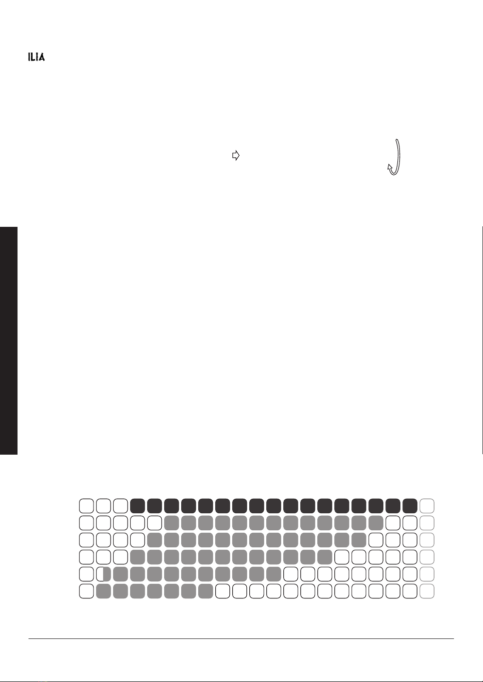
SETTING OF DIAPHRAGM FOR MODEL ERHS0712
has an internal 6 (0 Totally open ÷ 5 max closure) position diaphragm that can be used
where problems arise in the protected environment, for example the presence of direct
sunlight or awkward reflections or flare.
The diaphragm permits short distance adjustments and/or to have the beam pass through
narrow spaces or in any case to limit its size.
Receiver Unit Fix the key Turn clockwise
Diaphragm position 0
Distance from 30 m up to 200 m
Diaphragm position 1
Distance from 50 m up to 180 m
Diaphragm position 2
Distance from 40 m up to 170 m
Diaphragm position 3
Distance from 30 m up to 150 m
Diaphragm position 4
Distance from 15 m up to 120 m
Diaphragm position 5
Distance from 10 m up to 80 m
0 10 20 30 40 50 60 70 80 90 100 110 120 130 140 150 160 170 180 190 200 metri
POS 0
POS 1
POS 2
POS 3
POS 4
POS 5
ENGLISH
58 Mod. MII rev. 01
SETRONIC Verona

HIGH SENSITIVITY REFLECTION
SYSTEM DETECTOR
MODEL ERRHS0712
ENGLISH
Mod. MII rev. 01 SETRONIC Verona 59

REFLECTION VERSION
Basic characteristics
Ÿ Detector: Project, Technology, Design and Production fully made in Italy
Ÿ Suitable for use in all civil and industrial premises
Ÿ Very easy to install and program
Ÿ Low cost for mounting, cabling and maintenance
Ÿ The Detector can be installed horizontally or vertically and can work at any angle
Ÿ Micrometric adjustment for alignment
Ÿ Integrated diaphragm with a wide range of adjustment
Ÿ Control Unit for programming, calibration and performing of remote test on line beam
detectors:
Ø Basic configuration for two Detectors even of different types Transmitter /
Receiver or Reflection
Ø Expansion board for connection up to 3 to 8 detectors and line loop closure
(optional)
Ø Ground level installation for the Control Unit
Ø Alarm and Fault outputs can be programmed for each individual detector
Ø Operational access to keyboard protected by password
Ø Control Unit or Control Panel reset facility or by the MRS module
Ÿ Base
Ø Plug-in base to detector connection
Ø Base complete with back up board short circuit isolator to ensure continued
work even after a short circuit
Ÿ Special Allen Key suitable for mechanical alignment, diaphragm regulation, unhook of
detector base and open/close of control unit
Product characteristics
Ÿ Standard EN 54-12
Ÿ Protection rating IP65 (Transmitter- Receiver Unit, Reflection Unit and Controller Unit)
Ÿ RoHS Compatibility
Ÿ Operating distance 10 ÷ 150 m for Reflection model
Ÿ Width of cover up to 15 m
Ÿ Connections to 4 serial line conductor RS485
Ÿ Local and remote maintenance request
Ÿ Automatic threshold compensation
ŸAngle misalignment: ±1 degree max TRx Unit
±5 degree max Ref Unit
Ÿ Complete directional stability over time
Ÿ Sensitivity adjustable and selectable over a wide range, using the control unit model CSRLS
Ÿ Automatic reset of detector after break in infrared beam
Ÿ Self tester for RS485 communication
Ÿ Fault relay output delayed up to 90 seconds
Ÿ Power supply 24 V DC
Ÿ It is available, on request, the Control unit model CSRLS in the DUST version, with special
thresholds applicable in critical environments characterised by high levels of dust, steam or
other vapours
ENGLISH
60 Mod. MII rev. 01
SETRONIC Verona

SYSTEM DESCRIPTION
The ILIA mod. MODEL ERRHS0712 detector consists of a Transmitter/Receiver
Unit, with a Reflection Unit and a Beam Controller Unit for programming, setting
and testing. The Beam Controller Unit is used to remotely manage the detector or
detectors in the field using a single line. The Beam Controller Unit is put at a place
on ground level from where the detector can be controlled without having to climb
up to the detector, as regards all normal operations. The Beam Controller Unit is
made of plastic, has a keyboard for programming and a backlight 16x2 display.
By entering a password of 4 digits you can program the system from ground level to
determine the detector's signal level, to check environmental disturbances, to set
the required thresholds based on these and to check the alarm threshold; the
default password FFFF can be changed by the programmer by following the
instructions in the remote programming menu.
The system configuration menu becomes available when you just touch any of
the 5 buttons on the keyboard and by then entering the default password FFFF on
the first programming session, customising the password from then on (the
password can be reset if lost or forgotten by use of the Beam Controller Unit's reset
hardware).
The Beam Controller Unit electronic base permits direct connection of two detector
units; by means of an expansion circuit (SMLS), it is able to pilot up to 8 detectors
connected together and a connection with two stub lines or by a closed loop. With
this second typology the system continue proper working even if the cables are cut
or in the case of a short circuit by the protection circuit inserted in each single
detector. There are also programmable relay contacts in the unit for each individual
detector connected. These relays can have their polarity reversed with the use of
the software and permit the transmission to a single central unit of the individual
alarm, fault and maintenance request signals. Any breakdown in communication
between Beam Controller Unit and the detectors connected to it will be
immediately signalled by the simultaneous flashing of the yellow Led and the green
Led on the Transmitter and the Receiver, as well as being indicated on the display
of the Beam Controller Unit itself.
The controller is also available in the Dust version, suited to very difficult
environments, using special VdS certified software that enables the detection
threshold to be calculated up to the maximum limit permitted by standard EN54-12
without losing the principal characteristics of this model: producing early detection
in any environment.
ILIA with the Dust version controller has already come successfully through lab and
environmental real scale fire testing; these tests have shown that the model's
detection ability assures early alarm in any environment, overcoming unfavourable
conditions that could give rise to false or to fault alarms.
ILIA with the Dust version controller is thus a highly reliable response to the needs
of problematic environments with dust, steam, fumes or particular working
processes where other technologies are unable to assure the required security
and accurate and precise detection.
ENGLISH
Mod. MII rev. 01 SETRONIC Verona 61

The working voltage of the equipment is between 12 and 24 Volts without switching
(± 20%). The Transmitter/Receiver Unit emits a beam of modulated infrared light at
1 KHz in the form of a cone which crosses the space under surveillance to reach
the Reflection Unit. As the modulated infrared crosses the environment under
surveillance, it collects along its path all information that could suggest the start of a
fire. The events that intervene between Transmitter/Receiver Unit and Reflection
Unit affect the infrared carrier, alternatively optically modulating it in frequency and
in amplitude.
WORKING PRINCIPLE
The Transmitter/Receiver Unit demodulating from the infrared received the
information that is optically gathered, transforms each symptom of a possible fire
into corresponding electrical signals referable to “smoke”.
Such signals are electronically assessed by means of a special algorithm local to
the Transmitter/Receiver Unit, and are transmitted to the Beam Controller Unit. All
the units have a microcontroller that carries out a full scan of the working mode, i.e.
not only of the alarm, but also of faults, blinding and maintenance requests. The
messages are clearly given on the display and repeated by the four leds on the
Unit, as well as with the local led's on every individual piece of equipment. A
message on the display will indicate the type of event and the detector number.
Note: The Dip-Switch must always be used during installation to
determine the detector address number, also if is there only
one detector. In the loop configuration the Dip-Switch 4 must
stay in the «OFF» position.
The connection of one or more detectors is with leads of a minimum cross-section,
2
in accordance with current regulations, of 0.5 mm . For the type of cable to use
please refer to current regulations. It is not necessary to use shielded cable.
The detection of the start of a fire will mean information is sent from the field
(detector) to the Beam Controller Unit which will in turn send an alarm signal to a
central control unit. System resetting is possible both from the Beam Controller
Unit with a dedicated command or from the central control unit or closing, by a
normally open contact, the two terminal blocks of the MRS module.
The Beam Controller Unit can be used to set the blinding fault relay switching delay
for every individual detector, for times from 0 to 90 seconds.
The Transmitter/Receiver Unit (TRX) has an internal diaphragm that means it is
possible, following the instruction to mechanically set for the use of a diaphragm
filter to solve environmental problems in particular architectural situation where
there are awkward reflections or the optical beam must work in limited spaces or
get dirty before the starting up.
ENGLISH
62 Mod. MII rev. 01
SETRONIC Verona

ENGLISH
Mod. MII rev. 01 SETRONIC Verona 63
ASSEMBLY PROCEDURE
NOTE 1: Use the SETRONIC "Allen Key" for the opening and the closing of the detector and the
mechanical alignment of the equipment.
NOTE 2: to grant that the socket maintain the IP65 protection degree, be sure that i twill be fixed in flat
surface. If this it is not possible use a bracket or a swivel.
1. Fix the socket connection of the detector and carry out the wiring of the line (power supply and serial line).
2. Set the address of the detector between 1 and 8 consequently using the Dip-Switch according to the table on page 79.
It's suggested to make these operation before the fixing of the socket.
NOTE: The Dip-Switch 4 must be set to ON only in the last detector connected to the line open. It must
also be set with a single detector.
3. Insert the connector plug on the bottom of the detector into the socket until you hear a "click", then lock the unit to the
socket by rotating the hooks with the appropriate Allen key and guide it to the paired device from the opposite.
4. Repeat above operations for all the detectors are installed and the units of Reflection (Ref) omitting the part relating
to the connection line.
CONNECTIONS CHECK BEFORE START-UP
(to be made only with the loop configuration)
1. Disconnect the two terminals "power output" and "serial line" of the main module and the two terminals "power
output" and "serial line B" of the expansion module.
2. With a multimeter measure the resistance on the wires, between the positive output of the first power supply and
the positive of the second supply line. Also measure the resistance, always on the wires, between the negative
output of the first power supply and the negative of the second supply line.
3. Both resistance values read, must be less than 100 Ω
4. Reconnect the cables and make sure that the clamps are inserted securely.
CALIBRATION PROCEDURE
1. Power the system via the controller and set the number of detectors connected and the configuration of connection
to serial line. The controller also allows the use of the two serials in an independent manner, as if they were two
separate lines open. In this case, the addresses remain the same from set 1 to 8, but you set the end of the line (Dip-
Switch 4 to ON) of both the last detector.
2. At this point the green led of the two detector units should switch on and you must switch controller, a short flash
confirms the continuous scanning of the line. If on the units is present the condition of led flashing green and yellow
with flashes of about 2 sec., means that there is no serial communication (check the wiring for possible errors or
inversions) or incorrect configuration of the switch address. In such a case please verify: the cabling for possible
mistakes or inversions, the wrong configuration of the address switches (double same number) or the wrong
number of connected detectors (menu system set-up).
3. Point the TRx Unit by Allen key adjustment in order to obtain the led blinking yellow.
4. Starting i.e. from the left to move the unit slowly until the yellow led stops blinking. Then rotate the unit to the right
(the yellow led starts to flash again). Count how many turns of the key are made to obtain the yellow led off to the
opposite side. Reposition the center of movement found by dividing in half the number of revolutions counted. The
yellow led continues to blink.
5. Do the same for the vertical axis.
6. Point the unit of reflection following the same steps 3, 4, 5 and looking LEDs on the TRx Unit.
7. Perform the calibration by the ground controller to follow the menu <Auto Adjust.>.
8. Now cover the Reflection Unit with a card or opaque object. When you cover the Reflection Unit check that the
yellow led on the TRx Unit remains continuously on.

MAIN CALIBRATION PROCEDURES
1. Enter menu:
ž from the main screen, press OK;
ž enter the password, using the direction buttons „‚ƒ; press OK;
2. Set up detection lines:
ž press „ or ƒ until you get to < System Setup >; press OK;
ž press or ‚ to edit the number of the detection lines; press OK;
ž press or ‚ to change the delay time for fault outputs; press OK;
ž press or ‚ to change the configuration of fault outputs; press OK;
ž press or ‚ to set the <Com Line> configuration; press OK;
ž press OK to skip debug function.
3. First calibration of the detection lines (with mechanical adjustment of detectors):
ž press „ or ƒ until you get to < AUTO Adjust. >; press OK;
ž press or ‚ to change the number of the detection line to be worked on; press OK;
ž wait until the TX value stabilises and press OK;
ž the value of the RX must be about 100% (see note at pag. 72)
ž press OK to confirm the setting.
4. Calibration of detection lines (with the detectors already previously installed):
ž press „ or ƒ until you get to < AUTO Adjust. >; press OK;
ž press or ‚ to change the number of the detection line to be worked on; press OK;
ž wait until the TX value stabilises and press OK;
ž the value of the RX must be about 100% (see note at pag. 72)
ž press OK to confirm the setting.
5. Adjustment of detection line sensitivity:
ž press „ or ƒ until you get to < sensitivity >; press OK;
ž press or ‚ to change the number of the detection line to be worked on; press OK;
ž read the Detec value to quantify environmental disturbances;
ž press or ‚ to change the smoke threshold value (the value of the highest
disturbance value seen by Detec shall be less than the threshold setted) ; wait
for 2 sec and press OK;
ž read the Detec value to quantify environmental disturbances;
ž press or ‚ to change the fire threshold value (the value of the highest
disturbance value seen by Detec shall be less than the threshold setted);
ž wait for 2 sec and press OK to confirm the setting.
ENGLISH
64 Mod. MII rev. 01
SETRONIC Verona
This manual suits for next models
1
Table of contents
Other SETRONIC VERONA Security Sensor manuals

Popular Security Sensor manuals by other brands

Major tech
Major tech MT222 instruction manual

Friendtrol Technologies
Friendtrol Technologies TMS PLUS Series manual

Nova
Nova RF Series installation instructions

NETTROTTER
NETTROTTER Ecco freeze quick start guide

EscortRadar
EscortRadar REDLINE 360c quick start guide

Halma
Halma SENSITRON SMART3G-GrI manual


