Seura SW-2 User manual

OUTDOOR TV
SLIM WALL MOUNT
INSTALLATION GUIDE
Model Number:
SW-2
11 7
16"
26 1
4
"
7"
20 5
16"
25mm
1"
6"
11
16"
5"
WARRANTY REGISTRATION
REGISTER FOR
EXTRA BENEFITS
Activate within 30 days of purchase:
seura.com/activate
2
Prior to the installation of this product, read all
instructions. Keep this manual for future reference.
This product is designed to mount televisions and
any accessories weighing up to 220 lbs. to a vertical
CAUTION DO NOT EXCEED MAXIMUM LISTED
WEIGHT CAPACITY. SERIOUS INJURY OR PROPERTY
DAMAGE MAY OCCUR.
Warnings:
• Safety measures must be practiced at all times
during the assembly of this product. Use proper
safety equipment and tools for the assembly
procedure to prevent personal injury.
•
assembly procedure. Proper installation must
be followed as outlined in these installation
instructions. Personal injury and/or property
damage can result from dropping or mishandling
the TV.
• Ensure that there are no missing or defective
parts upon receipt. Never use defective parts.
• This product contains small parts that could be
a choking hazard.
•
of the television and the mount combined. A
professional installer or structural engineer
should inspect or verify the requirements of the
wall.
• Do not use this product for any purpose other
than to mount a VESA compliant TV on a vertical
surface as outlined in this manual.
• When mounting in metal stud walls or cinder
block walls, an alternative anchor (not included)
should used.
• If drilling and/or cutting into the mounting
surface, always make sure that the wall is clear
of electrical wires. Cutting or drilling into an
electrical line may cause serious personal injury.
• Make sure there are no water or natural gas lines
inside the wall where the mount is to be located.
Cutting or drilling into a water or gas line may
cause severe property damage or personal injury.
• Do not install near sources of high heat.
• Do not install on a structure that is prone to
vibration, movement or chance of impact.
Note: The included hardware is for mounting on
concrete, stone, brick, or wood studs . If you are
uncertain about the nature of your wall, please
consult your hardware or installation professional
for proper mounting to types of walls.
NOTE: RECESSED OUTLET REQUIRED
BECAUSE THE SLIM MOUNT ALLOWS THE TV TO SIT
TIGHTLY AGAINST THE WALL, TRADITIONAL WALL
OUTLETS DO NOT ALLOW ENOUGH CLEARANCE
FOR CABLES. UTILIZE EITHER RECESSED OUTLETS
OR REMOTE POWER LOCATIONS THAT ARE
COMPLIANT WITH YOUR LOCAL BUILDING CODES.
Safety
Compatible with Séura Outdoor TVs:
WARNING: Cancer and Reproductive

3
Parts Included
(2) Slim Mount TV
Brackets
11 7
16"
26 1
4
"
7"
20 5
16"
25mm
1"
6"
11
16"
5"
11 7
16"
26 1
4
"
7"
20 5
16"
25mm
1"
6"
11
16"
5"
Mounting Plate
261
4"
20 5
16
"11 7
16 "
25mm
1"
55
8
"
7"
115
16"
Wall Mounting Template
261
4"
20 5
16
"11 7
16 "
25mm
1"
55
8
"
7"
115
16"
Mounting Tools and Hardware
For concrete, brick, and
stone installation only
Phillips VESA Screws
Included with some
mount models
Wrench
Included with
some mount
models
261
4"
20 5
16
"11 7
16 "
25mm
1"
55
8
"
7"
115
16"
Screwdriver
Included with some
mount models
Screws
Included with some
mount models
4
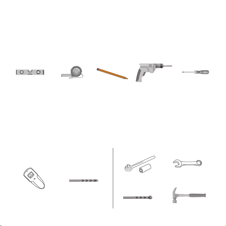
Parts and Tools Required (not included)
The following tools may be required depending on your particular installation. They are not included.
P5080T
Installation Instructions Visit the Premier Mounts website at http://www.premiermounts.com Page 3
Parts List
Installation Tools
The following tools may be required depending upon your particular installation. They are not included.
Pencil Level
¼˝ Drill Bit for
Wood Stud
Electronic Stud Finder
Socket Wrench Phillips Tip Screwdriver
Tape Measure
Hand Held Drill
Hammer**
3/8˝ Concrete Drill Bit*
Protective Eyewear
* Optional tools for concrete installations.
½˝ Socket M10 Socket*
2
1
5/16˝ x 3˝ Lag Bolts
(Qty 6)
Thread Depth Indicator
(Qty 1)
Universal Spacers
Finned Anchors
(Qty 6)
(Qty 24)
5/16˝ Flat Washers
(Qty 6)
Pro Mounting Hardware
Universal Washers
(Qty 6)
Security Barrel
(Qty 1)
Wall Plate
(Qty 1)
Universal Tilt Brackets
(Qty 2)
M6 x 60mm Screws
(Qty 2)
1/2”
1/2”
1/2”
1/2”
Level
Stud Sensor
(edge-to-edge stud
Tape Measure
Socket Wrench
Hammer
Wrench
Pencil Power Drill Philips #2
Screwdriver
Ultra Bright TV size)
For Wood Stud Installation For Concrete, Brick and Stone Installation
1/2”
1/2”
1/2”
1/2”
1/2”
1/2”

5
11 7
16"
26 1
4
"
7"
20 5
16"
25mm
1"
6"
11
16"
5"
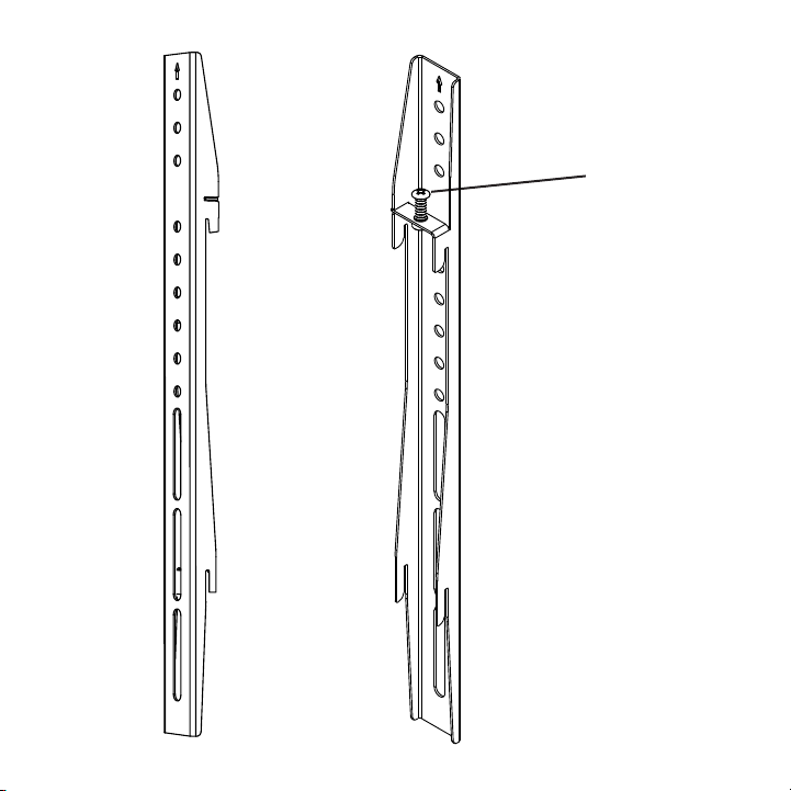
Top Leveling
Screws
Allows for leveling
adjustments of the
TV after mounting
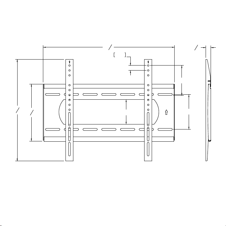
Mounting Slots
Allows for a
variety of stud
and lateral shift
adjustments
when mounting
your TV
Cable/Electrical Cut Out
Large center cut out is
convenient for power and
cable pass through with
wall plates
Directional
Mounting
Arrows
Lets you know
which edge
is up
Features

6
Installation
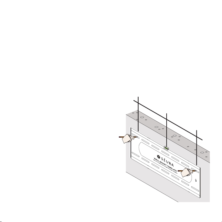
IMPORTANT: THIS PRODUCT MUST BE MOUNTED TO CONCRETE, STONE, BRICK OR WOOD STUDS. The wall
installer or structural engineer should inspect or verify the requirements of the wall.
2. Locate studs and mark the wall
All hole locations must be centered on wood studs.
Verify the center of the studs using an edge-to-
mark four hole locations in the template slots (2 top
and 2 bottom) with a pencil on the wall.
recommended.
IMPORTANT: HANDLE THE TV IN A VERTICAL POSITION TO AVOID DAMAGE TO THE
SCREEN. IF PLACING THE TV SCREEN-SIDE DOWN OR LEANING AGAINST A WALL DURING
INSTALLATION, COVER THE SCREEN WITH A PROTECTIVE CLOTH OR BLANKET.
Step 1: Hang the Mounting Plate
Wood stud wall mounting:
1. Choose mounting location
page 14 for measurements from the edges of the TV to the edges
of the mounting template to properly place the template in the desired location on the wall. Note that it is
NOT vertically centered on the TV screen.

7
3. Drill pilot holes
Pre-drill the four marked holes on the wall 3-inches
4. Attach mounting plate
Make sure the arrows on the mounting plate point
up. Align the mounting plate with the pre-drilled
holes. Attach mounting plate to wall using the
tighten the lag screws. Tighten the lag screws only
mounting plate.
8
2. Mark the wall
Level the template on the wall and mark four hole
locations in the template slots (2 top and 2 bottom)
with a pencil on the wall.
fasteners instead of four.
>12” >12”
Concrete, stone or brick wall mounting:
1. Choose mounting location
page 14 for measurements from the edges of the TV to the edges
of the mounting template to properly place the template in the desired location on the wall. Note that it is
NOT vertically centered on the TV screen.

9
3. Drill pilot holes
Pre-drill the four marked holes on the wall 3-inches
anchor into each of these holes. If necessary, lightly
tap each anchor into place with a hammer.
4. Attach mounting plate
Make sure the arrows on the mounting plate point
up. Align the mounting plate with the pre-drilled
holes. Attach mounting plate to wall using the four
the concrete surface even if there is another layer
of material, such as drywall. Do not over tighten
the lag screws. Tighten the lag screws only until
plate.

10
11 7
16"
26 1
4
"
7"
20 5
16"
25mm
1"
6"
11
16"
5"
Step 2: Attach Slim Mount TV Brackets to TV
IMPORTANT: Check your TV manual before attaching mount brackets
to TV. Some models require attaching soundbar brackets in tandem
with attaching mount brackets.
Bright TV), remove the four VESA mount screws from the back of the
back of the TV with the arrows pointed towards the top of the TV. Line
the brackets up with the VESA mount fastener locations. If mounting
be used on each Slim Mount TV Bracket. Attach the Slim Mount TV
Brackets to the TV using the same four VESA mount screws that you
just removed.
If installing with a soundbar or if
the TV’s VESA screws are not long
enough to attach the Slim Mount
TV Brackets, then use the four
are slightly longer than the TV’s
factory screws.
Shade Series
TV
Screw Size
Full Sun Series
TV
Screw Size
Note: Security Torx Screws (available with some mount models)
provide additional security to attach the brackets to the TV.
Installers may opt to use these in place of the TV’s VESA
screws, even if longer screws are not needed to accommodate a
soundbar bracket or mount brackets.

11
Step 3: Hang the TV
IMPORTANT: NEVER TRY TO HANG A TV BY YOURSELF. ALWAYS USE AT LEAST TWO PEOPLE TO LIFT THE TV
INTO PLACE.
261
4"
20 5
16
"11 7
16 "
25mm
1"
55
8
"
7"
115
16"
the wall, positioning it slightly above the mounting
plate.
2. Lower the TV to hook the bottom hooks of the
Slim Mount TV Brackets on the lower rail of the
mounting plate.
3. Bring the top of the TV closer to the wall to hook
the top hooks of the Slim Mount TV Brackets on
the top rail of the mounting plate.
engaged.
Do not let go of the TV until you are certain that the
top and bottom hooks of both mounting brackets
are securely engaged on the upper and lower
mounting rails of the mounting plate.
wind, and normal wear and tear can loosen
hardware over time.
12
Step 4: Adjust the TV
wind, and normal wear and tear can loosen hardware over time.
Top leveling screw adjustment:
If your TV is not level, the two (2) top leveling screws will allow you to compensate for this tilt by adjusting
2. Adjust the tilt of your TV.
3. Tighten both leveling screws.
Do not overtighten the leveling screws.
tighten the leveling and locking screws.
13
Top Leveling Screw
Allows for leveling
adjustments of the TV
after mounting.
11 7
16"
26 1
4
"
7"
20 5
16"
25mm
1"
6"
11
16"
5"
11 7
16"
26 1
4
"
7"
20 5
16"
25mm
1"
6"
11
16"
5"
14
Séura Outdoor TV Mounting Measurement Guide
the bracket hole listed to determine which holes on the Slim Mount TV Brackets to line up with the VESA
holes on the TV as described in Step 2.
Distance From Edges of TV to Edges of Mounting Template
Top of TV
to Top of
Mounting
Template
Bottom of TV
to Bottom
of Mounting
Template
Left Edge
of TV to
Left Edge
of Mounting
Template
Right Edge
of TV to
Right Edge
of Mounting
Template
Top Slim Mount TV Bracket
Hole
(line up with VESA hole on
back of TV in Step 2)
Second hole down from top
Second hole down from top
Second hole down from top
Top hole
Second hole down from top
Second hole down from top
Second hole down from top
Second hole down from top
Second hole down from top
Second hole down from top
Second hole down from top
Second hole down from top
Second hole down from top
Second hole down from top

15
Example Wall Location
11 1/8 in 11 1/8 in
6 3/16 in
14 13/16 in
SHD2-55 with Soundbar Outline
16
Specications
SLIM WALL MOUNT
Model: SW-2
GENERAL
DISPLAY COMPATIBILITY
VESA COMPARABILITY
MOUNTING PLATE DIMENSIONS
FINISH COLOR Black Powder Coat
DURABILITY Acrylic E-Coated Steel
INSTALLATION
MAXIMUM WEIGHT LIMIT 220 lbs
INSTALLATION SURFACE Solid / Brick / Stone / Masonry / Stud Wall
HARDWARE Stainless Steel
SHIPPING
SHIPPING CONTAINER DIMS
SHIPPING WEIGHT
PRODUCT WEIGHT
Maximum Weight Limit: 220 lbs.
structure must be reinforced.
17
11 7
16"
26 1
4
"
7"
20 5
16"
25mm
1"
6"
11
16"
5"

Publish date: December 5, 2022
Information is subject to change without notice.
www.seura.com
LIMITED PRODUCT WARRANTY
www.seura.com/warranty. If
Support to request warranty documentation from the date of your purchase.
Website: www.seura.com/support
Other manuals for SW-2
1
Table of contents
Other Seura TV Mount manuals


Popular TV Mount manuals by other brands


PEERLESS
PEERLESS Smartmount ST650 Installation and assembly

3idee
3idee hp-32s Assembly instructions

PEERLESS
PEERLESS HLG452-002 Installation and assembly manual

Zico
Zico QUIC-RELEASE QR-D-S Parts and instruction manual

Mustang
Mustang MPT-S22V instruction manual

Spectrum Industries
Spectrum Industries 37130 Assembly instruction