ABB AquaMaster IM9 User manual

FieldIT
Electronic Commercial Water Meter
AquaMasterTM
Installation Manual
IM/AM_9

ABB
EN ISO 9001:2000
Cert. No. Q5907
The Company
We are an established world force in the design and manufacture of
instrumentation for industrial process control, flow measurement, gas and
liquid analysis and environmental applications.
As a part of ABB, a world leader in process automation technology, we offer
customers application expertise, service and support worldwide.
We are committed to teamwork, high quality manufacturing, advanced
technology and unrivalled service and support.
Thequality,accuracyandperformanceoftheCompany’sproductsresultfrom
over100yearsexperience,combinedwith a continuousprogramof innovative
design and development to incorporate the latest technology.
TheUKASCalibrationLaboratoryNo.0255isjustoneofthetenflowcalibration
plants operated by the Company, and is indicative of our dedication to quality
and accuracy.
EN 29001 (ISO 9001)
Lenno, Italy – Cert. No. 9/90A
R
E
G
I
S
T
E
R
E
D
Health and Safety
To ensure that our products are safe and without risk to health, the following points must be noted:
1. The relevant sections of these instructions must be read carefully before proceeding.
2. Warning labels on containers and packages must be observed.
3. Installation, operation, maintenance and servicing must only be carried out by suitably trained personnel and in
accordance with the information given.
4. Normalsafetyprecautionsmustbetakentoavoidthepossibilityofanaccidentoccurringwhenoperatinginconditions
of high pressure and/or temperature.
5. Chemicalsmustbe stored away from heat, protected from temperature extremes andpowderskeptdry. Normal safe
handling procedures must be used.
6. When disposing of chemicals ensure that no two chemicals are mixed.
Safety advice concerning the use of the equipment described in this manual or any relevant hazard data sheets (where
applicable) may be obtained from the Company address on the back cover, together with servicing and spares
information.
Electrical Safety
Thisinstrumentcomplies with the requirements of CEI/IEC 61010-1:2001-2 "Safety requirements forelectricalequipmentfor
measurement, control, and laboratory use". If the instrument is used in a manner NOT specified by the Company, the
protection provided by the instrument may be impaired.
Symbols
One or more of the following symbols may appear on the instrument labelling:
Information in this manual is intended only to assist our customers in the efficient operation of our equipment. Use of this
manual for any other purpose is specifically prohibited and its contents are not to be reproduced in full or part without prior
approval of the Technical Communications Department.
Warning – Refer to the manual for instructions
Caution – Risk of electric shock
Protective earth (ground) terminal
Earth (ground) terminal
Direct current supply only
Alternating current supply only
Both direct and alternating current supply
The equipment is protected
through double insulation

1
CONTENTS
AquaMasterTM is a range of high performance
electromagnetic flowmeters for the measurement
of electrically conductive fluids and are normally
supplied as factory configured, calibrated
systems.
Warning.
• Installation and maintenance must be
carried out only by suitably trained
personnel.
• Read all relevant sections of this manual
before selecting a location.
• The safety requirements of this equipment,
any associated equipment and the local
environment must be taken into
consideration during installation.
• Install and use this equipment in
accordance with relevant national and local
standards.
• Specific safety precautions apply to the use
of the GSM engine which forms part of the
GSM-equipped version of this product. If
the unit purchased has GSM-capability,
read Appendix A on page 30 before
selecting a location.
1 INTRODUCTION
1 INTRODUCTION ........................................ 1
2 MECHANICAL INSTALLATION ................. 2
2.1 Unpacking .......................................... 2
2.2 Installation Conditions ........................ 2
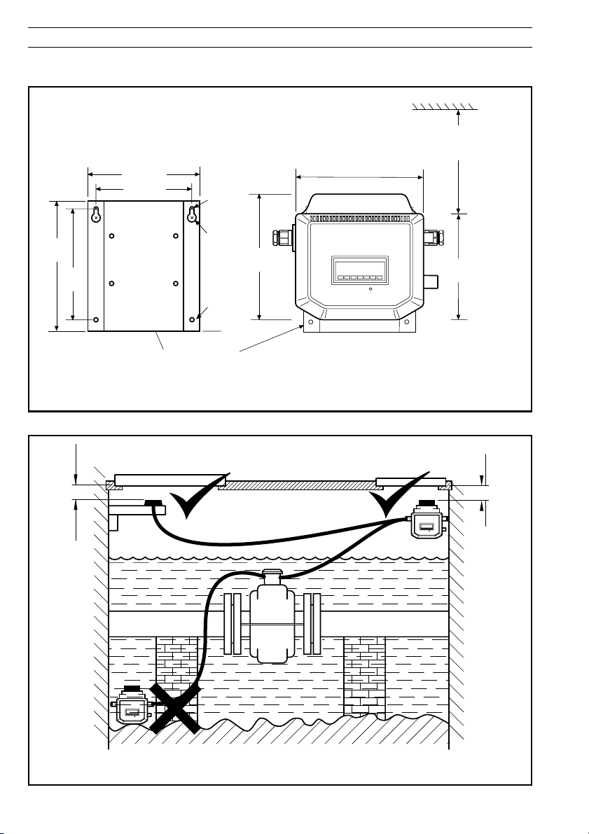
2.3 Transmitter Dimensions ...................... 4
2.4 GSM-equipped Transmitters .............. 5
2.4.1 GSM Antenna Installation ...... 5
2.4.2 Connecting a Remote
Antenna ................................. 6
2.4.3 Installing a SIM Card ............. 7
3 ELECTRICAL INSTALLATION ................... 8
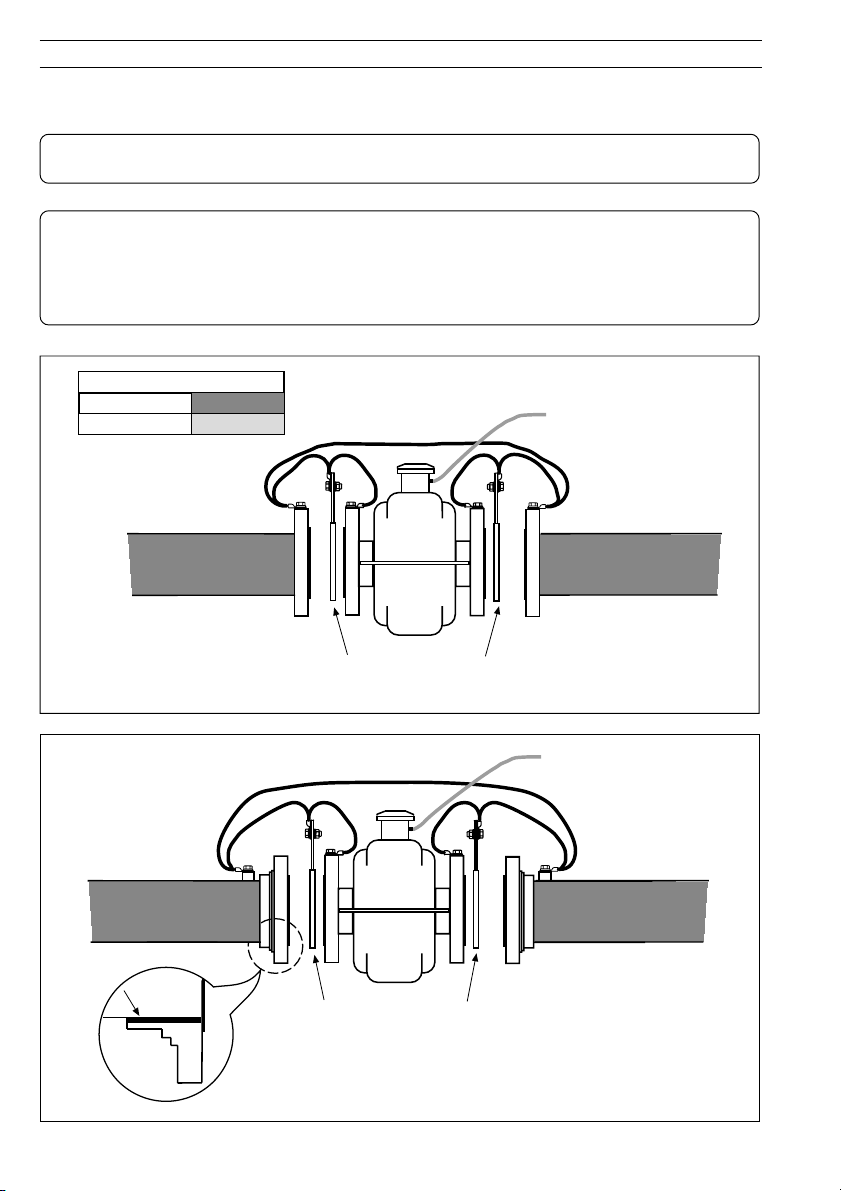
3.1 Bonding/Grounding ............................ 8
3.2 Connections ..................................... 13
3.2.1 Sensor Terminal Box
Connections (Remote
Versions only) ...................... 13
3.2.2 Environmental Protection ..... 13
3.2.3 Transmitter Connections ...... 14
3.3 Input/Output Connections ................ 17
3.3.1 Frequency Outputs .............. 17
3.3.2 Alarm Interface .................... 17
3.3.3 MIL Connector Input/Output
Connections (Option) ........... 18
3.3.4 MIL Connector Input/Output
(Option) – AquaMag™ x10
Pulse Output Compatibility .. 19
3.3.5 ScanReader Interface
(Option) ................................ 19
3.3.6 Local Computer
Connection .......................... 20
3.3.7 Remote Computer
Connection .......................... 21
3.3.8 Power Supply Connection ... 22
3.3.9 Pressure Transducer
(Optional) ............................. 23
3.3.10 Environmental Protection ..... 23
4 START-UP AND OPERATION .................. 24
4.1 Connecting Batteries ........................ 24
4.2 Start-up ............................................ 24
4.3 Display Activation ............................. 26
4.4 Replacing a Battery .......................... 26
4.4.1 Spares Kits. ......................... 27
4.4.2 Battery Changing
Procedures .......................... 28
APPENDIX A – GSM-EQUIPPED UNITS –
SAFETY PRECAUTIONS ............................... 30
APPENDIX B – AQUAMASTER BLOCK
DIAGRAM ....................................................... 31
SPECIFICATION ............................................. 32

2
Allow room to
read display
>2 x pipe dia.
minimum
>5 x pipe dia.
minimum
Flow Direction
60°C (140°F)
Maximum
–20°C (–4°F)
Minimum
AquaMaster
AquaMaster
AquaMaster
AquaMaster AquaMaster
2 MECHANICAL INSTALLATION
2.1 Unpacking
2.2 Installation Conditions – Figs. 2.1 to 2.17
Caution. Do NOT exceed the maximum
working pressure marked on the equipment.
Fig. 2.1 Unpacking
Fig. 2.2 Spillage
Fig. 2.3 Vibration
Fig. 2.4 Localized Heat
Fig. 2.5 Siting
Fig. 2.6 Straight Pipe Requirements
Fig. 2.7 Fluid Level
Fig. 2.8 Within Temperature Limits
Fig. 2.9 Shade

3
Supports
< 2 m
(78in)
IP68 (NEMA 6P/
ENCLOSURE 6P)
AquaMaster
Submerged
≤9 Months
Accrued Time
Backfill (Recommended)
Adequate
Protection
Plate
80°C (176°F)
Maximum
–10°C (14°F)
Minimum
Fit gaskets
Gasket same
size as pipe
0.7 m
minimum
For access to batteries, display
and communication connector.
AquaMaster
AquaMaster
2 MECHANICAL INSTALLATION…
Fig. 2.10 Above Ground
Fig. 2.11 Temperature Difference
Fig. 2.12 Within Environmental Rating
Fig. 2.13 Underground
Fig. 2.14 Cable Routing
Fig. 2.15 Gasket Fitting
Fig. 2.16 Separation of Sensors
Fig. 2.17 Access to Transmitter

4
Dimensions in millimeters (inches)
Transmitter Mounting Plate
176 (7)
140
(5.5)
Installation and wiring access
300 (11.8) minimum 450 (17.7)
preferred
Allowance for cable bend - each side
130 (5.1) – standard)
230 (9) – armored)
155mm
(6.1)
146 (5.75)
125 (4.9)
170
(6.7)
ø6.5 (1/4)
ø13 (1/2)
ø6.5 (1/4)
150
(5.9)
AquaMaster
…2 MECHANICAL INSTALLATION
2.3 Transmitter Dimensions – Fig. 2.18
Fig. 2.18 Transmitter Dimensions
50mm
50mm
Remote
Antenna
Integral
Antenna
Fig. 2.19 GSM Antenna Installation

5
≥50mm
Fig. 2.20 GSM Antenna Installation
2 MECHANICAL INSTALLATION…
2.4 GSM-equipped Transmitters
2.4.1 GSM Antenna Installation – Figs. 2.19 and 2.20
Before deciding on an antenna mounting location, check that the local signal strength for the chosen
mobile phone network is satisfactory. Use the GSM-equipped transmitter's integral signal strength test
facility to establish signal strength. Refer to 'Commissioning test for signal strength' in the Quick
Reference Guide for the AquaMaster S with GSM (IM/AMG–QRG).
If a GSM-equipped transmitter is not available, a standard mobile phone on the same network, positioned
as close as possible to the intended location, will give a good indication of local signal strength. For GSM
and logger download services, a minimum of two visible signal strength indicator 'bars' are
recommended. For SMS text, a minimum of one visible signal strength indicator 'bar' is recommended.
The following must also be observed when deciding on the antenna mounting location:
• For best results, mount the antenna as high above local ground level as possible.
• If the antenna must be mounted below ground, achieve optimum results by ensuring:
– there is a strong mobile phone network signal at ground level
– the antenna is mounted 50mm below the chamber cover, which must be plastic – see Fig. 2.19
• Ensure the antenna will not become submerged under water – see Fig. 2.19.
• Metallic enclosures will seriously degrade the signal. If an enclosure is used it must be non-metallic.
• Do not mount the antenna closer than 50mm to any solid wall or surface – see Fig 2.20.
• Do not mount the antenna beneath a solid surface (e.g. metal cover, floor/ceiling, etc).

6
SIM card
holder
Attach the antenna
cable plug securely
to the antenna
connector.
1If the transmitter is not fixed in any way, arrange or
hold it with the top cover uppermost.
2Wash off any loose dirt from the case using plain
water.
Remove the transmitter top cover and battery
mounting tray – see Fig. 3.12.
3
Pass the antenna cable through
a spare cable gland.
4
5
6Tighten the cable gland.
Refit the battery mounting tray and the transmitter
top cover – see Fig. 3.12.
7
…2 MECHANICAL INSTALLATION
…2.4 GSM-equipped Transmitters
2.4.2 Connecting a Remote Antenna – Fig. 2.21
Fig. 2.21 Connecting a Remote Antenna

7
2 MECHANICAL INSTALLATION
1If the transmitter is not fixed in any way, arrange or
hold it with the top cover uppermost.
2Wash off any loose dirt from the case using plain
water.
Remove the transmitter top cover and battery
mounting tray – see Fig. 3.12.
3
4
6Close the SIM card holder cover and slide into
locked position.
Refit the battery mounting tray and the transmitter
top cover – see Fig. 3.12.
7
Slide to unlock and open the
SIM card holder cover
5Insert the SIM card,
contact side down
and bevelled edge
first, into the SIM card
holder.
Fig. 2.22 Installing a SIM Card
…2.4 GSM-equipped Transmitters
2.4.3 Installing a SIM Card – Fig. 2.22

8
3.1 Bonding/Grounding – Figs. 3.1 to 3.9
Caution. For safety reasons and optimum performance, the flowmeter, pipelines and medium must
be correctly bonded and grounded according to regulations.
Notes.
• The flow sensor must not be connected to a ground spike.
• For bonding connections use ≥4mm2(<10AWG) cable.
• Sensors ≤80mm do not require grounding rings.
• Connect the transmitter ground connection to the flowmeter body ground – see Figs 3.6 and 3.7.
Fig. 3.1 All Metal Pipe, Including Lined Metal Pipe.
Fluid Contact Rings
See Figs. 3.6 and 3.7
Key for Figs. 3.1 to 3.9
Metal Pipes
Plastic Pipes
Fluid Contact Rings
See Figs. 3.6 and 3.7
Insulation
Fig. 3.2 Metal Pipe With Flange Adaptor
3 ELECTRICAL INSTALLATION

9
Fluid Contact Rings
See Figs. 3.6 and 3.7
Fluid Contact Rings
See Figs. 3.6 and 3.7
Fluid Contact Rings
See Figs. 3.6 and 3.7
Fig. 3.3 Flanged Metal Pipe to Plastic Pipe
Fig. 3.5 All Plastic Pipe
3 ELECTRICAL INSTALLATION…
Fig. 3.4 Metal Pipe With Plastic Make-Up Insert

10
…3 ELECTRICAL INSTALLATION
Fig. 3.6 Battery Powered Transmitter Mounted in a Chamber
Fig. 3.7 Mains or Battery Powered Transmitter in Roadside Cabinet with Local Ground

11
Fluid Contact Rings
Insulating Sleeve
and Washer
(not provided)
Insulated connecting wire
(not included). Must be
adequately rated to carry
cathodic currents.
Gasket Gasket
Supplied Bonding
Cable
Fluid Contact
Ring
Supplied Bonding
Cables
3 ELECTRICAL INSTALLATION…
Caution. Do NOT ground
Cathodically Protected Systems.
Fig. 3.8 Pipelines With Cathodic Protection, DN≥100mm

12
Insulating Sleeve
and Washer
(not provided)
Insulated connecting wire
(not included). Must be
adequately rated to carry
cathodic currents.
Gasket
Supplied Bonding
Cable
…3 ELECTRICAL INSTALLATION
Caution. Do NOT ground
Cathodically Protected Systems.
Fig. 3.9 Pipelines With Cathodic Protection, DN 40mm to 80mm

13
3 ELECTRICAL INSTALLATION…
3.2 Connections
3.2.1 Sensor Terminal Box Connections (Remote Versions only)
Caution. (Remote versions)
• Remove foil screens completely, and plastic/foil screens and any fillers
• Twist the three screen wires together and sleeve them.
• Keep cable pairs twisted.
• Make connections only as shown.
• Maintain Environmental Protection at all times.
• Conduit connections must provide cable entry sealing.
3.2.2 Environmental Protection
Warning.
• Potting materials are toxic – use suitable
safety precautions.
• Read the manufacturers instructions carefully
before preparing the potting material.
• The remote sensor terminal box
connections must be potted immediately
on completion to prevent the ingress of
moisture.
• Check all connections before potting – see
ELECTRICAL INSTALLATION.
• Do not overfill or allow the potting material
to come into contact with ‘O’ rings or
grooves.
• Do not let potting material enter conduit, if
used.
Fig. 3.11 Potting the Terminal Box
Caution. With Belden Cable 8777, ensure that the black wires are not interchanged, and
remain with the associated twisted pair.
1
3
2
7
––7 Violet
––6 Blue
––5 Sleeved Grounds
––4 Yellow
––3 Orange
––2 Red
––1 Brown
7 White
6 Black
5 Sleeved Grounds
4 Red
3 Black
2 Green
1 Black
ABB Belden 8777
Maximum Cable Lengths
STT 4000Series: ≤80m
STT 4005 Series: ≤250m
Belden 8777: ≤80m
CABLE
Fig. 3.10 Sensor Terminal box Connections (Remote Version)

14
…3 ELECTRICAL INSTALLATION
3.2.3 Transmitter Connections – Figs. 3.12 to 3.15
Caution.
• To ensure cable glands seal, use cable of diameter 2 to 6mm (0.08 to 0.24 in) [M16] only.
• Ensure cable glands are tightened after wiring.However, overtightening a plastic cable gland will
break it and destroy its sealing property. It is recommended that cable glands are tightened finger-
tight initially, then a further 1/2to 3/4turn applied using a suitable spanner.
• Ensure that ‘O’ ring seals and mating surfaces are clean, to maintain environmental rating.
• For IP68 protection where the transmitter could be submerged, the termination area must be
potted – see Section 3.3.9.
Slacken captive screws
Lift off
Cover
1
2
Remove battery tray
3
Press and ...
...lift
Fig. 3.12 Transmitter Connection Terminal Access
Note. The batteries are
mounted in the lid of early style
transmitters.

15
3 ELECTRICAL INSTALLATION…
Caution. (Remote versions)
• Remove foil screens completely, and plastic/foil screens and any fillers
• Twist the three screen wires together and sleeve them.
• Keep cable pairs twisted.
• Make connections only as shown.
• Maintain Environmental Protection at all times.
• Conduit connections must provide cable entry sealing.
Fig. 3.13 Transmitter Connections (Glands/Conduit Entry)

16
…3 ELECTRICAL INSTALLATION
Fig. 3.15 Sensor Cable Connections (Connector, Remote version)
Note. This arrangement is an option.
17
1 Brown(BN)
2 Red (RD)
3 Orange (OR)
4 Yellow (YL)
5 Sleeved Ground
6 Blue (BL)
7 Violet (VI)
ABB Belden 8777
CABLE
1 Black
2 Green
3 Black
4 Red
5 Sleeved Ground
6 Black
7 White
Fig. 3.14 Sensor Cable Connections (Gland/Conduit, Remote version)
Caution. With Belden Cable 8777,
ensure that the black wires are not
interchanged and remain with the
associated twisted pair.

17
3 ELECTRICAL INSTALLATION…
3.3 Input/Output Connections
Caution.
• Refer to SPECIFICATION for Input/Output ratings.
• Inductive loads must be suppressed or clamped to limit voltage swings
• Operation of outputs is programmable – see Quick Reference Programming Guide for details.
• External isolators are not normally required as the pulse and alarm circuit is electrically separated
from all other AquaMaster connections.
• Capacitive loads must be inrush current limited.
• Fully-floating pulse outputs may be subject to static damage, e.g. connecting to a floating
datalogger, unless 'COM' is operated within its galvanic isolation range (±35 V) from earth.
Recommended protection for floating output systems is to wire 'COM' to '0V'.
3.3.1 Frequency Outputs – Fig. 3.16
Fig. 3.16 Frequency Output Connections
Fig. 3.17 Alarm Output Connections
Note. Outputs 1 & 2 are not polarity sensitive. The common
connection for these outputs is designated ‘COM’.
Note. Output 3 is not polarity sensitive.
The common connection for these outputs is designated ‘COM’.
Alarm functions are available only with product software
versions: ≥1.1 (Release 1) ≥2.1 (release 2). See
Programming Guide to determine software version.
Telemetry, Electronic
Counters etc.
Counter/Totalizers
Forward Flow
and/or
Reverse Flow
123456
123456
I/P0V*
COM
O/P1
O/P2
PLC or Datalogger
COM
O/P1
O/P2
Common
Input 1
Input 2
*Optional link for grounding floating
output. See Caution above.
I/P0V
COM
O/P1
O/P2
COM
O/P3
Common
Alarm Input
I/P0V*
*Optional link for grounding floating output.
See Caution above.
I/P0V
COM
O/P3
3.3.2 Alarm Interface – Fig. 3.17

18
…3 ELECTRICAL INSTALLATION
3.3.3 MIL Connector Input/Output Connections (Option) – Fig. 3.18
# When Remote Comms.
Option is fitted
* Not fitted on older cables
† Note Caution regarding
fully floating outputs.
Recommended protection
for floating output systems is
to connect G to J.
Fig. 3.18 MIL Connector Connections
niPemaNnoitcnuF roloC
)elbaCtuptuO(
A– devreseR
B– devreseR
C– devreseR
D1P/O esreveR&drawroFrosesluPdrawroF
sesluP egnarO
E3P/OtuptuOmralAdeR/etihW
F2P/OrotacidnInoitceriDrosesluPesreveReulB
GmoCP/O
†
nommoC niarD
S/eriWneerc
H– devreseR
JdnGP/InommoCtupnIetihW
K+P/ItupnItcatnoCteloiV
LDXR#)noitcennoctupnilaires(atadevieceResiouqruT
MDXT#)noitcennoctuptuolaires(atadtimsnarTnworB
NSTR#dnesottseuqeR*kcalB/deR
PSTC#dnesotraelC*deR/wolleY
R– devreseR
S– devreseR
TIR#rotacidnIgniRwolleY
U– devreseR
VDNGlaireS#dnuorGsmmoCneerG
This manual suits for next models
1
Table of contents
Other ABB Measuring Instrument manuals

ABB
ABB Aztec 600 User manual

ABB
ABB LWT300 series User manual

ABB
ABB Advance Optima Caldos 15-Ex User manual

ABB
ABB CoriolisMaster FCM2000 Installation and operation manual

ABB
ABB CoriolisMaster FCB100 User manual

ABB
ABB ACX Installation and operation manual

ABB
ABB aquamaster User manual

ABB
ABB GLA131 Series User manual

ABB
ABB MR Series Manual

ABB
ABB AW101 User manual