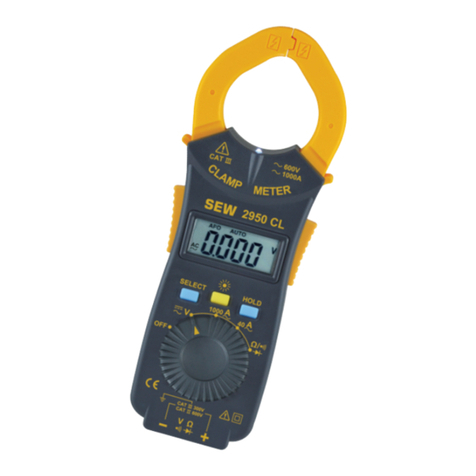
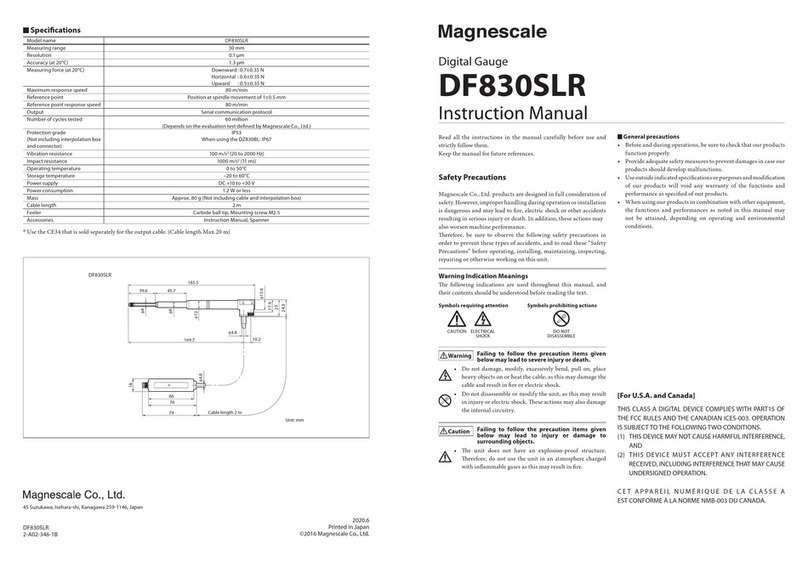
SEW 2940 CL User manual

AC CLAMP METER
INSTRUCTION MANUAL
2940 CL
SELECT HOLD
C
L
A
M
P
M
E
T
E
R
4
3.999
V

Index
1. Introduction..........................................
2. Safety notes.........................................
3. Features..............................................
4. Specications......................................
5. Instrument layout.................................
6. Measurement......................................
7. Maintenance........................................
Page
1
2-3
3
4-6
7-8
9-10
11

-1-
1. Introduction
Note
This meter has been designed and tested according to
CE Safety Requirements for Electronic Measuring
Apparatus, EN 61010-1 EN 61010-2-32 and other safety
standards. Follow all warnings to ensure safe operation.
Warning
Read "Safety Notes"(next page) before using the meter.

-2-
2. Safety Notes
Read the following safety information carefully before
attempting to operate or service the meter.
● Use the meter only as specied in this manual,
otherwise the protection provided by the meter may
be impaired.
●Always keep hands behind the meter barrier.
●Use extreme caution when clamping around
uninstalled conductors or bus bars.
●Never clamp around any conductor carrying a voltage
above 600V R.M.S.
●During current measurement to avoid an electric
shock accident, do not connect the test leads to the
instrument.
●To avoid electric shock when measuring live lines,
wear appropriate protective gear, such as insulated
rubber gloves and boots.
●Rated environmental conditions:
(1) Indoor use.
(2) Installation Category II 600V
Category III 300V
(3) Pollution Degree 2.
(4) Altitude up to 2000 Meter.
(5) Relative Humidity 80% Max.
(6) Ambient Temperature 0~40℃.

-3-
●Observe the international electrical symbols listed
below.
Meter is protected throughout by double
insulation or reinforced insulation.
Warning ! Risk of electric shock.
Caution ! Refer to this manual before using the
meter.
Alternating current.
Direct current.
Earth (ground).
3.Features
●4000-count LCD.
●Full automatic measurement.
AC Current measurement.
AC/DC Voltage measurement.
Resistor measurement.
●Data Hold function.
●Continuity check.
●Diode measurement.
●Low battery indication.
●Auto-off function.
●Flashlight.
●Safety Standard :
EN 61010-1 CAT II 600V / CAT III 300V
EN 61010-2-32
EN 61326-1
▬
…

-4-
4. Specications
AC Current
Range Resolution Accuracy
400.0A 0.1A ±(2.0%rdg+5dgt)
(40~200Hz)
1000A 1A
AC Voltage
Range Resolution Accuracy
4.000V 1mV ±(1.5%rdg+10mV)
(40~500Hz)
40.00V 10mV
±(1.5%rdg+5dgt)
(40~500Hz)
400.0V 100mV
750V 1V
● Input impedance : 10MΩ
DC Voltage
Range Resolution Accuracy
4.000V 1mV
±(1.0%rdg+5dgt)
40.00V 10mV
400.0V 100mV
1000V 1V
● Input impedance : 10MΩ

-5-
Resistance
Range Resolution Accuracy
400.0Ω 0.1Ω
±(1.5%rdg+3dgt)
4.000kΩ 1Ω
40.00kΩ 10Ω
400.0kΩ 100Ω
4.000MΩ 1kΩ
40.00MΩ 10kΩ ±(2.0%rdg+4dgt)
Threshold level (beep sound) : less than 25Ω
●Overload protection :
ACV 750V rms
DCV 1000V
Diode & Ohm 250V rms
●Conductor size : 35mm
●Low battery indication :
" " sign appears on the display.
●Response time :
Approx. 1 second.
●Sample rate :
Approx. 2 times per second.

-6-
●Operating temperature and humidity :
0°C~40°C 80% R.H. Max.
●Storage temperature and humidity :
-10°C~50°C 80% R.H. Max.
●Battery life :
Approx. 100 hours on continuity use.
●Dimension :
183(L) × 62(W) × 20(D)mm
●Weight : Approx 123g (battery included)
●Power source : DC 3V (CR2032) battery × 1
●Accessories :
Instruction manual
Test leads
Soft pouch
Battery

-7-
5. Instrument layout
⑴ Transformer Jaws ⑹ Function Switch
⑵ Flashlight ⑺ Input Terminal
⑶ Jaw Trigger ⑻ SELECT Push Button
⑷ LCD ⑼ Flashlight Button
⑸ Data Hold Button ⑽ Barrier
(1)
SELECT HOLD
C
L
A
M
P
M
E
T
E
R
4
(2)
(3)(3)
(4)
(5)
(6)
(7)
(9)
3.999
(8)
(10)
V

-8-
(1) Transformer Jaws
Pick up the conductor within the jaws center.
(2) Flashlight
For easier viewing in the dark.
(3) Jaw Trigger
Press to open the jaws.
(4) LCD
3¾ digit LCD with maximum reading of 3999.
(5) Data Hold Button
Freeze the reading for all ranges with "HOLD"
indicated.
(6) Function Switch
For function selection
(7) Input Terminal
"+" and "-" terminal
(8) SELECT Push Button
For select function :
a. ACV / DCV
b. Ω / /
(9) Flashlight Button
For ashlight function
(10) Barrier
Provide a protective distance from hands to
conductor.

-9-
6. Measurement
Before proceeding with measurement, read the safety
notes.
(1) AC current measurement
●Set the function switch to " A" range.
●Press the jaw trigger to open the transformer
jaws and clamp onto one conductor only.
●Read the display reading directly.
(2) ACV measurement
●Insert the BLACK test lead to (-)terminal and the
RED one to the other terminal.
●Set the function switch to " ▬
…V" range and press
the SELECT button, until the " AC " symbol
appears.
●Connect the test leads to the object to be
measured.
●Read the display.
(3) DCV measurement
●Insert the BLACK test lead to (-)terminal and the
RED one to the other terminal.
●Set the function switch to " ▬
…V" range.
LOADLOAD LOADLOAD
SELECT HOLD
C
L
A
M
P
M
E
T
E
R
SELECT HOLD
C
L
A
M
P
M
E
T
E
R
O X

-10-
●Connect the test leads to the object to be
measured.
●Read the display.
Note
Reversing the polarity of the test leads displays
a negative value.
(4) Resistance measurement
●Insert the BLACK lead to the (-)terminal and the
RED one to another.
● Set the function switch to "Ω / / " range and
make sure there is no power in the circuit being
measured.
●Connect the test leads to the object under test
and read the display directly.
(5) Continuity test
●Insert the BLACK lead to the (-)terminal and the
RED one to another.
● Set the function switch to "Ω / / " range and
press the "SELECT" button, until the " "
symbol appears.
●Connect the test leads to the object under test.
●The buzzer will work when the resistance is less
than 25Ω.
(6) Diode test
● Turn the function switch to "Ω / / " setting
and press the "SELECT" button twice, until the
" " symbol appears.

-11-
●Connect the 2940 CL red and black test lead,
red test lead should connect Diode (+Anode)
black test lead should connect Diode (-Cathode).
The display will show the reading.
7. Maintenance
(1) Battery Replacement:
When low battery warning appears, change a new
battery as follows:
Disconnect the test leads from the instrument and
turn off the power. Unscrew the battery cover and
replace with a new battery.
(2) Cleaning and storage:
WARNING
To avoid electrical shock or damage to the meter,
do not get water inside the case.
Periodically wipe the case with a damp cloth and
detergent. Do not use abrasives or solvents.
If the meter is not to be used for a long time over
60 days, please remove the battery for storage.
Table of contents
Other SEW Measuring Instrument manuals
