sewerin AQUAPHON A 200 User manual

16.09.2019 a – 107378 – en
AQUAPHON®
A 200 receiver
Operating Instructions

A 200 receiver
Connectors
Fig. 1: Front
Fig. 2: View from above
LED
Light sensor
Touch screen
Connectors
Charging socket
USB port
Microphone socket
ON/OFF key
Activation keys
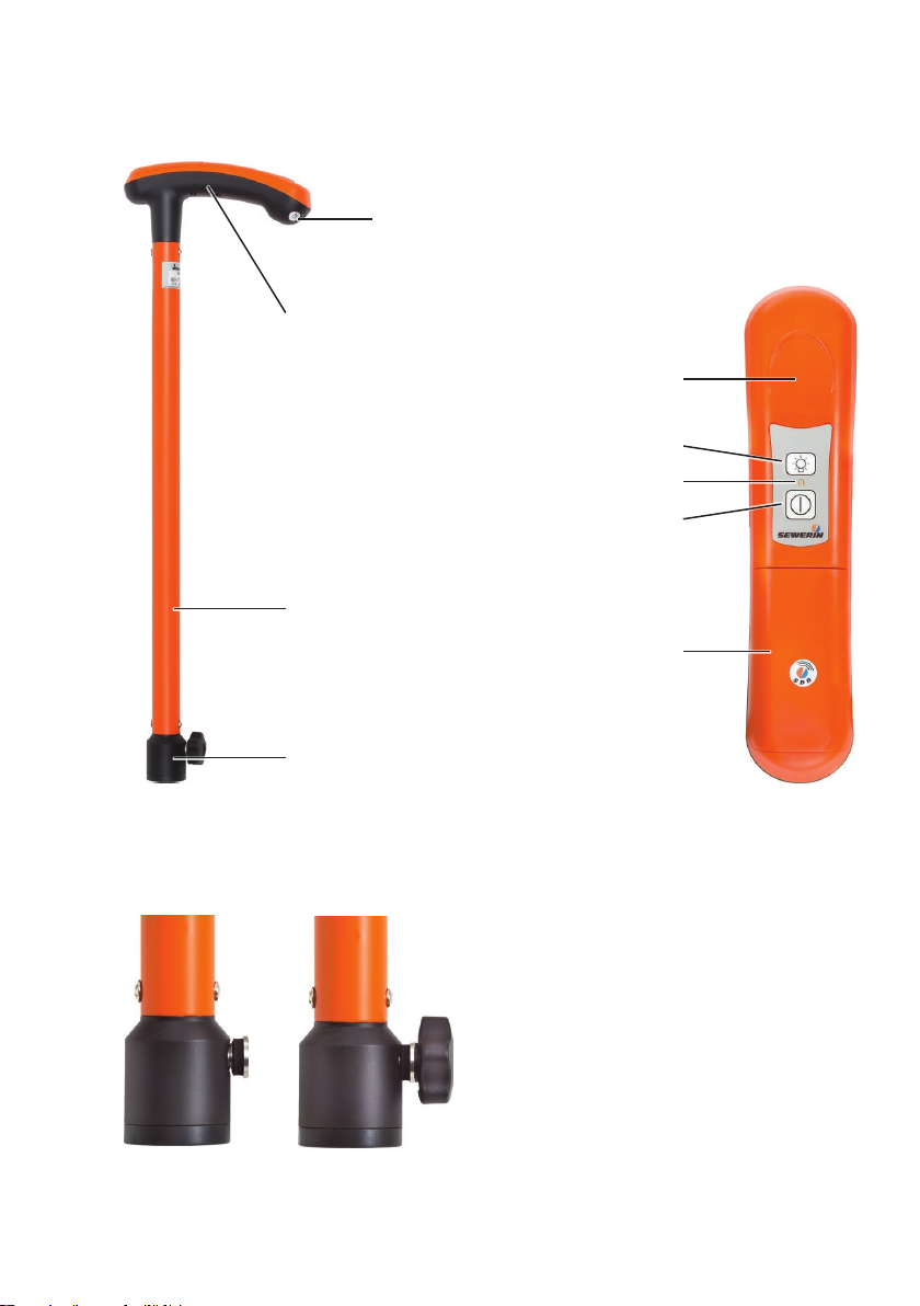
TS 200 carrying rod
Charging socket
Fig. 3: Full view
Sensor area
Fig. 4: Handle (view from above)
Fig. 5: Adapter
Left image: Fastening screw with seal
Right image: Star knob in fastening screw
Handle
Pipe
Adapter
Light key
LED
ON/OFF key
Battery compartment cover

Information about this document
The warnings and notes in this document mean the following:
AWARNING!
Risk of personal injury. Could result in serious injury or death.
ACAUTION!
Risk of personal injury. Could result in injury or pose a risk
to health.
NOTICE!
Risk of damage to property.
Note:
Tips and important information.
Numbered lists (numbers, letters) are used for:
●Instructions that must be followed in a certain order
Lists with bullet points (point, dash) are used for:
●Lists
●Instructions that only involve one step

Contents│ I
1 Introduction .............................................................................1
1.1 Warranty....................................................................................1
1.2 Purpose.....................................................................................2
1.3 Intended use .............................................................................2
1.4 General safety information ........................................................3
2 AQUAPHON system................................................................4
2.1 General information about the system ......................................4
2.1.1 Communication ......................................................................4
2.1.2 Hearing protection..................................................................4
2.1.3 Operating concept..................................................................4
2.1.3.1 Switch-on mode ..................................................................5
2.1.3.2 Applications.........................................................................6
2.1.3.3 Contact points .....................................................................6
2.2 System components..................................................................7
2.2.1 Overview ................................................................................7
2.2.2 A 200 receiver ........................................................................7
2.2.2.1 Product variants ..................................................................7
2.2.2.2 Setup...................................................................................8
2.2.2.3 Carrying the system ..........................................................10
2.2.2.4 Playing back noises ..........................................................10
2.2.2.5 Displaying the measurement values .................................10
2.2.2.6 Automaticpowero .......................................................... 11
2.2.2.7 Main view .......................................................................... 11
2.2.3 TS 200 carrying rod..............................................................15
2.2.4 Microphones.........................................................................16
2.2.4.1 Microphones depending on the application (overview).....16
2.2.4.2 UM 200 universal microphone ..........................................18
2.2.4.3 Other microphones............................................................18
2.3 Switchingonando................................................................19
2.3.1 Components.........................................................................19
2.3.2 System .................................................................................19
2.4 Power supply to the components ............................................20
3 Using the system ..................................................................21
3.1 Attaching the microphone to the carrying rod .........................21
3.2 Switching on the system .........................................................21
3.2.1 Startup with user guide ........................................................22
3.2.2 Direct startup........................................................................24
3.3 Naming measurements ...........................................................24

II │Contents
3.4 Starting and ending a measurement .......................................25
3.5 Adjusting the hearing protection threshold and volume ..........25
3.6 Adjustingtheltersettings ......................................................27
3.6.1 Notesontheltersettings....................................................27
3.6.1.1 Filter limits and stopband ..................................................27
3.6.1.2 Default settings for every application ................................28
3.6.1.3 Purpose of adjustment ......................................................28
3.6.1.4 Adjustment options............................................................28
3.6.1.5 Displayofadjustedltersettingsinthemainview............29
3.6.2 Opening the Filter menu.......................................................29
3.6.3 Scanning ..............................................................................30
3.6.4 Manuallyadjustinglters......................................................31
3.6.4.1 Adjustinglterlimitsquickly ..............................................31
3.6.4.2 Adjustinglterlimitsprecisely ...........................................31
3.6.5 Scaling the display ...............................................................33
3.6.6 Resettingltersettings.........................................................33
3.7 Playing back noise repeatedly ................................................34
3.7.1 Opening the Audio Player menu ..........................................34
3.7.2 Playing back noise ...............................................................36
3.7.2.1 Playingbacknoisewithrecordedlterlimits.....................36
3.7.2.2 Playingbacknoisewithcurrentlterlimits........................37
3.7.2.3 Playing back noise faster ..................................................37
3.8 Saving recorded measurements .............................................38
3.9 Deleting the recorded measurement.......................................39
3.10 Loading a saved measurement...............................................39
3.11 Deleting a saved measurement ..............................................41
3.12 Displaying information about a measurement.........................43
3.13 Locking and unlocking the display ..........................................44
4 Settings ..................................................................................45
4.1 Overview .................................................................................45
4.2 Setting actions.........................................................................45
4.2.1 Selecting ..............................................................................46
4.2.2 Enabling/disabling ................................................................46
4.2.3 Setting a value .....................................................................47
4.3 Settings in the Measurement menu ........................................47
4.3.1 Method .................................................................................48
4.3.2 Type .....................................................................................49
4.3.3 Hearing protection................................................................49
4.3.4 Activation keys .....................................................................49

Contents│ III
4.3.5 Timer ....................................................................................50
4.3.6 Duration................................................................................51
4.3.7 TS: Sensor area ...................................................................51
4.4 Setting the application.............................................................51
4.5 Settings in the Device menu ...................................................52
4.5.1 Switchingothedevice .......................................................54
4.5.2 Switchingothebacklight....................................................54
4.5.3 Automatic brightness............................................................54
4.5.4 Brightness ............................................................................55
4.5.5 Time .....................................................................................55
4.5.6 Date......................................................................................55
4.5.7 Date format ..........................................................................55
4.5.8 Time format ..........................................................................56
4.5.9 Language .............................................................................56
4.5.10 Information ...........................................................................56
4.5.11 Calibration ............................................................................56
5 Maintenance ..........................................................................57
5.1 Charging the batteries.............................................................57
5.1.1 Charging the batteries in the case .......................................57
5.1.2 Charging batteries individually using the AC/DC adapter
or vehicle cable ....................................................................58
5.2 Handling faulty lithium-ion rechargeable batteries ..................59
5.2.1 Identifying faulty batteries ....................................................59
5.2.2 Removing the batteries from the A 200 receiver ..................60
5.2.3 Removing the battery from the TS 200 carrying rod ............61
5.3 Calibrating the touch screen ...................................................63
5.4 Care ........................................................................................64
5.5 Maintenance............................................................................64
6 Appendix................................................................................65
6.1 Technical data .........................................................................65
6.1.1 A 200 receiver ......................................................................65
6.1.2 TS 200 carrying rod..............................................................66
6.1.3 BM 200 and BM 230 ground microphones...........................68
6.1.4 TM 200 touch microphone ...................................................68
6.1.5 UM 200 universal microphone .............................................69
6.2 Symbols on the touch screen of the A 200 receiver ................70
6.3 SignicanceofLEDsignals....................................................72
6.3.1 A 200 receiver ......................................................................72
6.3.2 TS 200 carrying rod..............................................................73

IV │Contents
6.4 Suitability of the microphones for the applications ..................74
6.5 Operating the system by activation key or sensor area ..........75
6.6 Accessories.............................................................................76
6.7 Declaration of conformity ........................................................76
6.8 Noteaboutthermware(opensourcesoftware)....................77
6.9 Advice on disposal ..................................................................77
7 Index.......................................................................................78

1 Introduction│ 1
1 Introduction
1.1 Warranty
The following instructions must be complied with in order for any
warranty to be applicable regarding functionality and safe oper-
ationofthisequipment.
●Read these operating instructions prior to operating the prod-
uct.
●Use the product only as intended.
●Repairs and maintenance must only be carried out by special-
ist technicians or other suitably trained personnel. Only spare
parts approved by Hermann Sewerin GmbH may be used
when performing repairs.
● Changesormodicationstothisproductmayonlybecarried
out with the approval of Hermann Sewerin GmbH.
●
Use only Hermann Sewerin GmbH accessories for the product.
Hermann Sewerin GmbH shall not be liable for damages result-
ing from the non-observance of this information. The warranty
conditions of the General Terms and Conditions (AGB) of Her-
mann Sewerin GmbH are not broadened by this information.
In addition to the warnings and other information in these Oper-
ating Instructions, always observe the generally applicable safety
and accident prevention regulations.
The manufacturer reserves the right to make technical changes.

2 │1Introduction
1.2 Purpose
AQUAPHON is a system for the acoustic location of water leaks
and water pipes.
The AQUAPHON system can be used for:
●Leak detection
●Pipe location
Note:
All descriptions in these operating instructions refer to the system
as delivered (factory settings). The operating instructions apply
to the A 200receiverwithrmwareversion2.xandhigher.The
manufacturer reserves the right to make changes.
1.3 Intended use
The AQUAPHON system is intended for professional industrial
and commercial use. The appropriate specialist knowledge is
requiredtooperatethesystem.
Note:
If necessary, learn more about the principles of the technology
before commencing practical work with the system.
Thesystemmustonlybeusedfortheapplicationsspeciedin
section 1.2.

1 Introduction│ 3
1.4 General safety information
This product was manufactured in keeping with all binding legal
and safety regulations. It corresponds to the state-of-the-art and
conformstoECrequirements.Theproductissafetooperate
when used in accordance with the instructions provided.
However, if you handle the product improperly or not as intend-
ed, the product may present a risk to persons and property. For
this reason, observe the following safety information without fail.
Risk of personal injury (health risk)
●
Handle the components carefully and safely both during trans-
port and when working.
● Proceedwithextremecautioninthevicinityofelectricallines.
Hazards for the product and other property
●Always handle the components carefully.
●Do not drop the components.
●Do not place the components in places where they are at risk
of falling.
●Before starting work, check that the components are in good
working order. Never use damaged or defective components.
●Ensure that no dirt or moisture gets into the connections on
the components.
●Always observe the permitted operating and storage temper-
atures.

4 │2AQUAPHONsystem
2 AQUAPHON system
2.1 General information about the system
2.1.1 Communication
The components of the AQUAPHON system communicate by
bidirectional SDR (SDR: Sewerin Digital Radio). Wireless com-
munication allows the user considerable freedom of movement.
Thesoundqualityoftheacousticplaybackisnotaectedby
swinging cables.
2.1.2 Hearing protection
The AQUAPHON system protects the user's hearing against
sudden, loud interference noise. This type of interference noise
canoccur,forexample,whenvehiclesdrivebyorwhentheuser
withatouchmicrophoneslipsothecontactpoint.
The hearing protection function activates when the individu-
alhearingprotectionthresholdsettingisexceeded.Whenthe
noise from the source of interference ceases, hearing protection
switchesoagainautomatically.
The way the hearing protection works depends on the settings
(Measurement menu > Hearing protection).
Note:
Another way of protecting the hearing from loud noises is to set
the volume only as high as is absolutely necessary.
2.1.3 Operating concept
Working with the AQUAPHONsystemrequiresspecialistknowl-
edgeofleakandpipelinelocation.Youdonot,however,require
any special skills to use the system itself, as it can guide you
through the process.
To ensure successful location with the AQUAPHON system, all
users must know:

2AQUAPHONsystem│ 5
●What is to be located?
The purpose determines the choice of application.
●Where is it to be located?
Conditions on the ground determine the choice of contact
point.
2.1.3.1 Switch-on mode
The receiver always automatically determines the switch-on
mode. There are two options:
●Startup with user guide
●Direct startup
The situation when the receiver is switched on determines which
switch-on mode is used. The receiver checks whether or not cer-
tain steps have already been performed. These steps include:
●System components have been connected (e.g. carrying rod
and a ground microphone).
●
System components have already been switched on before
the receiver.
For more detailed information about switching on dependent on
switch-on mode, please refer to section 3.2 on page 21.
Startup with user guide
Target
group:
Userswithlittleexperienceofusingthesystem.
– The user is unsure of which system components
to select for a certain application and the corre-
sponding contact point.
Theuserrstswitchesonthereceiver.Onceanapplicationand
the contact point have been selected, the receiver provides de-
tailed instructions about which components are to be connected
and switched on in what order.
Direct startup
Target
group:
Experiencedusers.
– The user knows which components of the sys-
tem to select for a certain application and the
corresponding contact point.

6 │2AQUAPHONsystem
The user starts by selecting the suitable components. Compo-
nents that need to be connected mechanically are connected
by the user. The user then switches on the components before
switching on the receiver last. The receiver automatically recog-
nises the components as it is switched on.
With Direct startup, the system is ready to use as soon as the
receiver is switched on.
2.1.3.2 Applications
The names of the applications correspond to their possible uses.
The system can be used for:
●Leak detection
●Pipe location
2.1.3.3 Contact points
Each application allows the system to be used on certain contact
points. The contact point is the area on which a microphone is
placed.
The following contact points can be selected:
●Paved
Thecontactpointhasasmooth,rmsurface(e.g.asphalt,
concrete, plaster).
●Unpaved
The contact point has an uneven surface, which may some-
times give way (e.g. gravel, crushed stone, grass).
●Fitting (only for leak detection)
Thecontactpointis,forexample,ahydrantorslidegate.
●Universal (only for leak detection)
The contact point is located inside a building.
This option is intended for locating leaks and pipes with the UM
200 universal microphone.

2AQUAPHONsystem│ 7
2.2 System components
2.2.1 Overview
The AQUAPHON is a modular system. The main system com-
ponents are as follows:
●A 200 receiver
●F8 wireless headphones
●TS 200 carrying rod
Thecarryingrodisrequiredwhenusingthefollowingmicro-
phones:
−BM 200 ground microphone
−BM 230 ground microphone (with tripod)
−TM 200 touch microphone
Aprobetipandpossiblyanextensionarerequiredforthe
touch microphone.
●UM 200 universal microphone
●AC 200 SK4 case
The system can be transported and stored in the case. The
batteries for the components A 200, TS 200 and F8 can be si-
multaneously charged in the case using the AC/DC adapter L.
Accessories can be added to the system at any time.
Note:
Information about F8 wireless headphones can be found in the
relevant operating instructions.
2.2.2 A 200 receiver
2.2.2.1 Product variants
The receiver is available in two product variants:
●without module for position determination
●with module for position determination

8 │2AQUAPHONsystem
Devices with position determination link the measurement data
with the geographical coordinates (e.g. GPS) of the measuring
location.
Receivers with position determination module are
identiedbyasticker.
2.2.2.2 Setup
Overviews with the names of all the parts of the receiver can be
foundinsidethefrontcover(g.1andg.2).
Its symmetrical housing means that it can be operated by both
right-handed and left-handed users with ease.
Touch screen
The receiver features a touch screen. Certain areas of the touch
screen are touch-sensitive. Actions are performed by touching
these areas (buttons).
All of the buttons have a thick, dark grey outline.
Onlyyourngeroratouchpenshouldbeusedtooperatethe
touch screen.
●
Alwaystouchthebuttonsbrieywithoutexertingtoomuch
pressure.
NOTICE! Risk of damage
The surface of the touch screen is sensitive.
●Do not use any hard or sharp objects (e.g. pens) to operate
the screen.
●Protect the touch screen against aggressive substances (e.g.
acidic or abrasive detergents).
Overviews with the symbols that might appear on the touch
screen can be found in section 6.2 on page 70.
Light sensor
The light sensor analyses the ambient lighting conditions.

2AQUAPHONsystem│ 9
If the automatic brightness setting is enabled, the light sensor
always adjusts the brightness of the touch screen to the ambient
lighting conditions.
Information about the automatic brightness setting can be found
in section 4.5.3 on page 54.
ON/OFF key
The ON/OFF key has the following functions:
● Switchingthereceiveronando
●Locking and unlocking the display
Activation keys
The receiver has two activation keys. Only one of the two keys
needs to be pressed to measure.
LED
The LED indicates the operating status.
Information about what the LED signals mean can be found in
section 6.3.1 on page 72.
Ports
The receiver features the following ports:
●Charging socket
For charging the rechargeable battery.
●Microphone socket
For connecting the UM 200 universal microphone.
●USB port
For connecting to a computer.
Connectors
Carrying systems (Vario, lap belt), the triangle 200 carrying strap
or a hand loop can be attached to the connectors.
Theconnectorsarepartsofthequick-releasefasteners.

10 │2AQUAPHONsystem
2.2.2.3 Carrying the system
The receiver is usually carried in front of the body so that the user
looks diagonally down at the touch screen.
SEWERIN recommends: Use a carrying system for locating op-
erations. The carrying system prevents you from tiring during
work. It also reduces the possibility of radio interference. Ra-
dio interference can occur if the user accidentally covers certain
components in the receiver.
2.2.2.4 Playing back noises
The connected microphone records noises. When a measure-
ment is ongoing, the noises are played back through the head-
phones. You can set the volume of the playback.
The noises are also recorded. Recorded noises can be saved.
Both recorded and saved noises can be played back.
2.2.2.5 Displaying the measurement values
Various measurement values are calculated from the recorded
noises(e.g.currentnoiselevel,extremevalueofthemeasure-
ment).
The measurement values can be displayed in two ways:
●Visually
●Numerically
Visual representation
The measurement values are displayed visually on the touch
screen in the main view (volume button):
●Current noise level (level display)
● Extremevalue(blackline)
Numerical representation
The measurement value for the noise level is displayed as a nu-
meric value in the centre of the main view on the touch screen.
Thismeasurementvalueisanextremevalue.Whethertheex-
tremevalueisaminimumormaximumdependsonthesettings
(Measurement menu > Type).

2AQUAPHONsystem│ 11
2.2.2.6 Automatic power o
The power supply to the receiver is designed in such a way that
a fully charged battery will allow one full day's work without in-
terruption. However, it is still recommended to conserve energy
whilst working.
Thereceiverthereforeoersthefollowingautomaticpower-o
options:
●Switch o device
Thereceiverswitchesoifitisnotoperatedforaspecied
period of time. It must be switched back on again when you
want to continue work.
●Switch o backlight
Thereceiverbacklightswitchesoifitisnotoperatedfora
speciedperiodoftime.Thereceiverremainsswitchedon.
Ifandwhentheautomaticpoweroisactivateddependsonthe
settings (Device menu > General > Switch o device or Switch
o backlight).
2.2.2.7 Main view
The touch screen of the receiver displays the main view when
the system is ready for use.
Fig. 6: Main view, here: during a measurement
The measurement value for the noise level is displayed in the
centre of the main view. The duration of the current measurement
and the symbol for satellite reception are displayed above it, if the
12 │2AQUAPHONsystem
device is set accordingly. The values are black during a measure-
ment.Assoonasameasurementisnished,theyappeargrey.
The main view also contains the following buttons:
●Volume
●Audio player
●Filter
●Settings
These buttons can be used to open submenus. The buttons also
display information. The information displayed depends on the
situation.
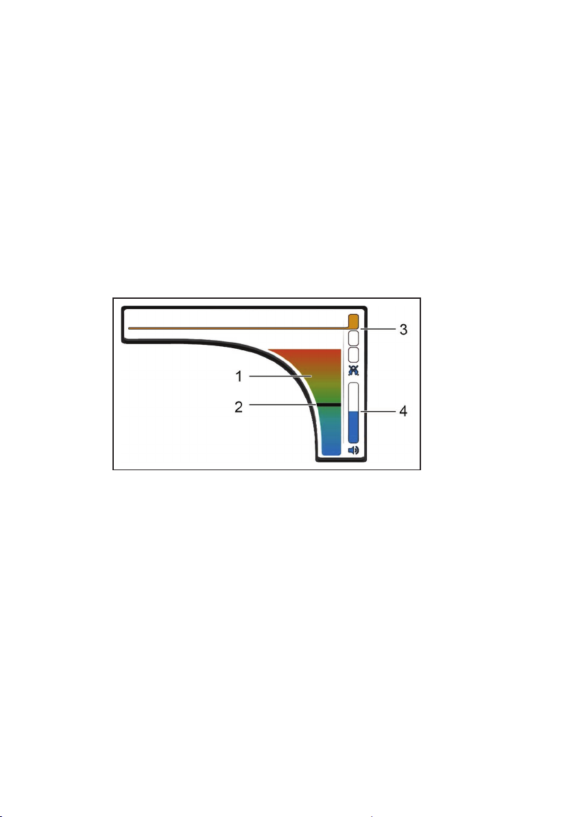
Volume
Fig. 7: Volume button
1Currentnoiselevel,2Extremevalue,
3 Hearing protection threshold, 4 Volume
The Volume button displays the following information:
●Current noise level
● Extremevalue
●Hearing protection threshold setting
●Volume setting
The Volume menu is opened using the Volume button. The fol-
lowing settings can be made in this menu:
●Hearing protection threshold
●Volume
Table of contents
Other sewerin Receiver manuals


