sewerin AQUAPHON AF 50 User manual

02.09.2019 a – 107762 – en
AQUAPHON®
AF 50 receiver
Operating Instructions
AF 50 receiver
Arrow keys
●Up key
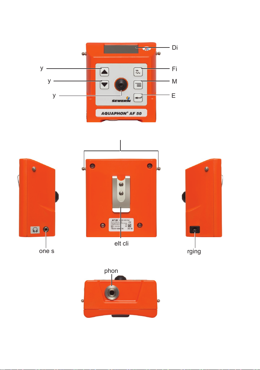
Fig. 1: Receiver AF 50 viewed from various angles
●Down key
Activation key
Display
Filter key
Menu key
Enter key
Belt clip
Headphone socket
Connection for
microphone/search coil
Charging socket
Fastener knobs
AF 50 receiver
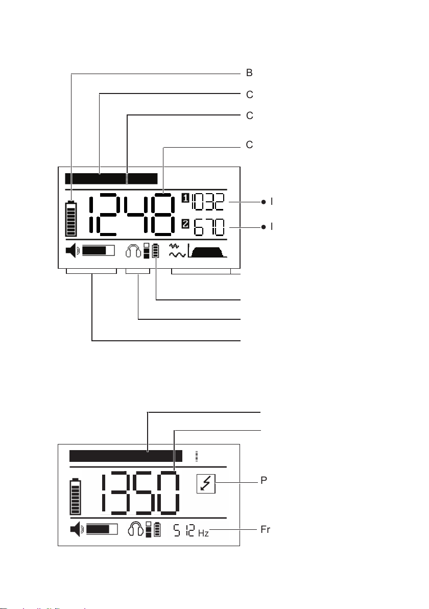
Fig. 2: Display with main view during water leak detection
Battery symbol for receiver
Current noise level (bar)
Current minimum noise level
(marker)
Minimum noise level
●last but one
Filter level
Battery symbol
wireless headphones
Hearing protection level
Volume
Current minimum noise level
●last
Hz
Fig. 3: Display with main view during pipeline location
Power line
Frequency
Field strength
●Bar display
●Numerical display

Illustration of warnings in this document
AWARNING!
Risk of personal injury. Could result in serious injury or death
ACAUTION!
Risk of personal injury. Could result in injury or pose a risk
to health.
NOTICE!
Risk of damage to property.

Contents│ I
1 Introduction .............................................................................1
1.1 Information about this document...............................................1
1.2 Purpose.....................................................................................1
1.3 Intended use .............................................................................2
1.4 Safety information .....................................................................2
2 AQUAPHON system................................................................4
2.1 Acoustic water leak detection....................................................4
2.2 Pipe location..............................................................................4
2.2.1 Passive pipeline location........................................................4
2.2.2 Active pipeline location...........................................................4
2.3 Hearing protection.....................................................................5
2.4 System components..................................................................5
2.4.1 Overview ................................................................................5
2.4.2 AF 50 receiver........................................................................7
2.4.2.1 Setup...................................................................................7
2.4.2.2 Display rotation ...................................................................8
2.4.2.3 Carrying the system ............................................................8
2.4.2.4 Activation key......................................................................8
2.4.3 Display of the results in the main view ...................................9
2.4.4 Power supply........................................................................ 11
2.4.5 UM 50 universal microphone ...............................................12
2.4.6 SK 3 search coil ...................................................................13
2.5 Dierencesbetweenapplicationswhenlocating ....................13
3 Using the system ..................................................................14
3.1 Preparing the system ..............................................................14
3.2 Starting up the system ............................................................14
3.2.1 Connecting the microphone or search coil...........................14
3.2.2 Connecting headphones ......................................................15
3.2.2.1 F8 wireless headphones ...................................................15
3.2.2.2 K3 headphones.................................................................15
3.3 Adjusting the volume...............................................................16
3.4 Performing water leak detection..............................................16
3.4.1 Starting and ending a measurement ....................................16
3.4.2 Adjustingthelter.................................................................17
3.4.2.1 Adjusting the bandpass.....................................................17
3.4.2.2 Activatingthenotchlter...................................................18

II │Contents
3.5 Performing pipe location .........................................................19
3.5.1 Setting the frequency ...........................................................19
3.5.2 Using the maximum or the minimum method.......................19
3.5.3 Applyingautomaticamplieradjustment..............................21
3.6 Switchingothesystem..........................................................21
4 Settings ..................................................................................22
4.1 Overview .................................................................................22
4.2 Backlight (LIGHT)....................................................................22
4.3 Operating mode (ACTIVATION) ..............................................23
4.4 Display rotation (DISPLAY) .....................................................24
4.5 Hearing protection (MUTE) .....................................................25
4.6 Hearing protection threshold (PROTECT) ..............................25
4.7 Factory settings (RESET) .......................................................27
5 Maintenance ..........................................................................28
5.1 Charging the batteries.............................................................28
5.1.1 Charging the batteries in the case .......................................28
5.1.2 Charging batteries individually using the AC/DC adapter
or vehicle cable ....................................................................29
5.2 Handling faulty lithium ion rechargeable batteries ..................30
5.2.1 Identifying faulty batteries ....................................................31
5.2.2 Removing the battery from the receiver ...............................31
5.3 Care ........................................................................................32
5.4 Servicing .................................................................................32
6 Appendix................................................................................33
6.1 Technical data .........................................................................33
6.1.1 AF 50 receiver......................................................................33
6.1.2 UM 50 universal microphone ...............................................35
6.2 A 50 receiver ...........................................................................36
6.2.1 Adjustablelters...................................................................36
6.2.1.1 Bandpass ..........................................................................36
6.2.1.2 Notchlter.........................................................................36
6.2.2 Factory settings....................................................................37
6.3 Accessories.............................................................................38
6.4 Declarations of conformity.......................................................38
6.5 Advice on disposal ..................................................................38
7 Index.......................................................................................39

1 Introduction│ 1
1 Introduction
1.1 Information about this document
This document is a component part of the product.
●Read the document before putting the product into operation.
●Keep the document within easy reach.
●Pass this document on to any subsequent owners.
● Unlessotherwisespecied,theinformationinthisdocument
refers to the product as delivered (factory settings) and applies
to all product variants.
Translations
Translations are produced to the best of our knowledge. The
original German version is authoritative.
Right of reproduction
Nopartofthisdocumentmaybeedited,duplicatedorcirculated
in any form without the express consent of Hermann Sewerin
GmbH.
Registered trademarks
Registered trademarks are generally not indicated in this docu-
ment.
1.2 Purpose
The AQUAPHON system with the AF 50 receiver is designed for
waterleakdetectionandpipelinelocation,especiallyinbuildings.
The system can be used for:
●
Preliminarydetectionofwaterleaksinttings(e.g.hydrant,
slide gate)
● Pinpointingwaterleaksonpavedsurfaces(e.g.asphalt,con-
crete,paving,ush-mounted)
●Locating and tracking lines

2 │1Introduction
Note:
These operating instructions describe the functions of the AF 50
receiverwithrmwareversion1.xxx.
All descriptions in these operating instructions refer to the system
as delivered (factory settings). The manufacturer reserves the
right to make changes.
1.3 Intended use
The product is suitable for the following uses:
●professional
●industrial
●commercial
Theproductmustonlybeusedfortheapplicationsspeciedin
section 1.2.
Note:
The appropriate specialist knowledge is required for using this
product.
1.4 Safety information
This product was manufactured in keeping with all binding legal
and safety regulations.
The product is safe to operate when used in accordance with the
instructionsprovided.However,whenhandlingtheproduct,there
mayberiskstopersonsandproperty.Forthisreason,observe
the following safety information without fail.
●Observe all the applicable safety standards and accident pre-
vention regulations.
●Use the product only as intended.
●
Donotmake any changes ormodications to theproduct
unless these have been expressly approved by Hermann
Sewerin GmbH.

1 Introduction│ 3
●
Only use accessories and consumables approved by Hermann
Sewerin GmbH.
●Always observe the permitted operating and storage temper-
atures.
● Handletheproductcarefullyandsafely,bothduringtransport
and when working.
● Alwaysadequatelycordonotheworkarea.
● Whenyouarewearingheadphones,youarenotfullyaware
ofambientnoise.Beespeciallyvigilant,especiallyinenviron-
mentswithanincreasedriskofaccident(e.g.roadtrac).
●Do not use the product if it is damaged or faulty.
● Protecttheportsandsocketsagainstdirt,andelectricalports
in particular against moisture.

4 │2AQUAPHONsystem
2 AQUAPHON system
2.1 Acoustic water leak detection
Water leak detection includes preliminary detection and pinpoint-
ing. A microphone must be connected to the AF 50 receiver to
be located acoustically with the AQUAPHON system. The mi-
crophone picks up noises and plays them back through a set
of headphones. This means that leak noise can be detected in
pipelines.
2.2 Pipe location
Analternatingcurrentmustowthroughalinetobelocated.
The SK 3searchcoildisplaystheeldstrengthfromtheAF 50
receiver and transmits it as an audible signal to the connected
headphones.
A distinction is made between the following location techniques:
●Passive
●Active
2.2.1 Passive pipeline location
Forlinesthatarenotonlyenergizedbutalsounderload,the
alternating current required for location is already available. The
appropriate receiving frequency can be set at the AF 50 receiver:
●50 Hz
●60 Hz
2.2.2 Active pipeline location
The alternating current is produced using a generator (e.g. gen-
erator FG 50). The following frequencies can be set at the AF
50 receiver:
●512 Hz
●1.1 kHz
●9.95 kHz

2AQUAPHONsystem│ 5
Display of current-carrying lines
Ifthereisanenergizedlinenearthesearchcoil,thereceiverwill
display the power line symbol.
Hz
Fig. 4: Display of a current-carrying line ( power line symbol)
2.3 Hearing protection
Thesystemfeaturesahearingprotectionfunction,whichpro-
tects the user from sudden loud sound interference. Such sound
interferencecanoccur,forexample,whentheuserslipsothe
contact point using a microphone.
Hearingprotectionisactivatedwhenthepredenedhearingpro-
tection threshold is exceeded. When the noise from the source
ofinterferenceceases,hearingprotectionswitchesoagainau-
tomatically.
The way in which hearing protection works depends on the set-
tings (section 4.5 and section 4.6).
Note:
Another way of protecting the hearing from loud noises is to set
the volume only as high as is absolutely necessary.
2.4 System components
2.4.1 Overview
The AQUAPHON is a modular system. The main system com-
ponents are as follows:

6 │2AQUAPHONsystem
●AF 50 receiver with SDR1radio module
● Headphones,e.g.
−F8 wireless headphones
−K3 headphones (wired)
Additional components for water leak detection:
● Microphones,e.g.
−UM 50
Microphones have to be used in conjunction with accessories:
−Probe tips and extensions (available in various lengths)
−M 10 tripod
−M 10 contact adapter
Additional components for pipeline location:
●SK 3 search coil
Foractivepipelinelocation,thefollowingisalsorequired:
●Generator (e.g. FG 50 generator)
●Universal set of cables
Thecomponentsofthesystemcanbetransported,storedand
loaded in the SK 10 case.
Additional accessories can be added to the system at any time.
Note:
Detailed information about the headphones and the FG 50 gen-
erator can be found in the associated operating instructions.
1Sewerin Digital Radio
2AQUAPHONsystem│ 7
2.4.2 AF 50 receiver
2.4.2.1 Setup
Foroverviewsincludingallpartnamesforthereceiver,seethe
frontcoverap(g.1).
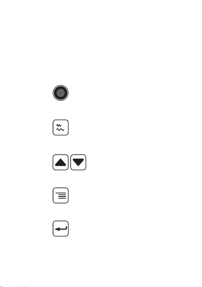
Keys
The receiver has the following keys:
●Activation key Water leak detection:
For starting and ending a measurement
(listening to noises).
Pipeline location:
Forautomaticamplieradjustment.
●Filter key Water leak detection:
For switching between the main view
and the Filter view.
Pipeline location:
For selecting the receiving frequency.
●Arrow keys
For adjusting the volume.
Forchangingsettingsandlterlimits.
●Menu key For switching between the main view
and the Settings view.
●Enter key In the Filter and Settings views:
For selecting the variables to be set.

8 │2AQUAPHONsystem
Ports
The receiver has the following connections:
●Charging socket For charging the rechargeable battery.
The following can be connected:
– M4 AC/DC adapter
– M4 vehicle cable
●Connection for micro-
phone/search coil
For connecting a microphone or a
search coil.
The following can be connected:
– UM 50 universal microphone
– SK 3 search coil
●Headphone socket For connecting the K3 headphones.
Connectors
The EA carrying strap can be attached to the connectors.
2.4.2.2 Display rotation
The orientation of the display can be adjusted to the position in
which the receiver is used. If the receiver is rotated through 180°
aboutitslongitudinalaxis,thedisplayrotatestoo.Thisfunction
ensuresthatthedisplayremainseasytoread,regardlessofthe
position in which the receiver is used.
2.4.2.3 Carrying the system
The receiver can be carried as follows when in use:
●worn around the neck (with the EA carrying strap)
●clipped to the waistband (with the belt clip)
●held in the hand
2.4.2.4 Activation key
The function of the Activation key varies according to the appli-
cation.

2AQUAPHONsystem│ 9
Water leak detection
The Activation key is used to start and stop measurements. There
are two operating modes available for this:
●Hold mode
The Activation key is held down for the duration of the meas-
urement.
●Toggle mode
TheActivationkeyispressedbrieytostartthemeasurement.
TheActivationkeyispressedbrieyagaintoendthemeas-
urement.
The operating mode is selected in the settings (section 4.3).
Pipe location
TheActivationkeyactivatesautomaticamplieradjustment(sec-
tion 3.5.3).
2.4.3 Display of the results in the main view
Themainviewonthedisplaydiersdependingontheapplica-
tion.
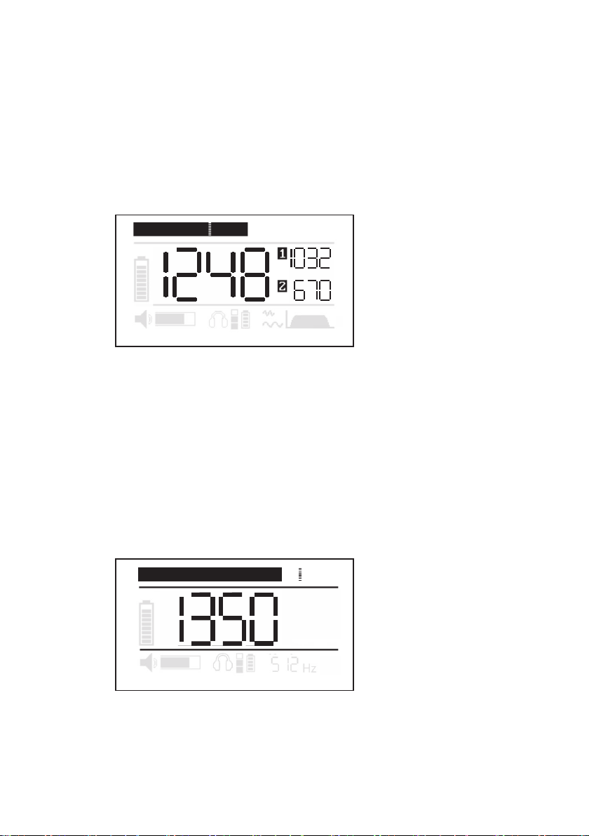
Water leak detection
Noise levels are measured during water leak detection. The fol-
lowing noise levels are simultaneously shown on the display
(g.5):
●Current noise level
The current noise level is always displayed as soon as the sys-
tem is ready for use. It is displayed in the form of a black bar.
●Minimum noise level
The minimum noise level relates to an ongoing or completed
measurement.
−Current minimum noise level
The current minimum noise level is displayed in the middle
of the main view as a numerical value and as a marker in
the bar.
10 │2AQUAPHONsystem
−Previous minimum noise level
Whenameasurementhasbeencompleted,whatwasuntil
then the current minimum noise level is displayed as the
last minimum noise level next to [1].
−Last but one minimum noise level
Whenthenextmeasurementhasbeencompleted,thelast
minimum noise level becomes the last but one minimum
noise level and is displayed next to [2].
Fig. 5: Graphical and numerical noise level display for water leak detection
Top: current noise level (bar) and
current minimum noise level (marker in bar)
Middle: current minimum noise level (here: 1248)
Right: [1] previous minimum noise level (here: 1032) and
[2] last but one minimum noise level (here: 670)
Pipe location
Duringpipelocationthe strength of electromagnetic elds is
measured.Theeldstrengthmeasuredisdisplayedonthedis-
play both numerically and as a bar.
Hz
Fig. 6: Chartandnumericaldisplayoftheeldstrengthduringpipe
location
Top: bar display
Middle: numerical display (here: 1350)

2AQUAPHONsystem│ 11
2.4.4 Power supply
The A 50receiverispoweredbyaspecial,permanentlyinstalled
lithium ion rechargeable battery.
NOTICE! Reduced battery life when not in use
The battery in the receiver can discharge (self-discharge) even
when the receiver is not in use.
●You should charge the battery at least once every 6 months.
Information about charging the rechargeable battery can be
found in section 5.1.
NOTICE! Risk of damage when changing the lithium ion
battery
There are parts in the receiver that can be damaged mechan-
ically or by electrostatic discharge when changing the battery.
●
Only SEWERIN service personnel or other authorised special-
ists may replace the lithium ion rechargeable battery.
AWARNING! Risk of explosion due to short-circuit
Faulty lithium ion rechargeable batteries can explode due
to internal short-circuit.
●
Components containing faulty lithium ion batteries must
not be shipped.

12 │2AQUAPHONsystem
2.4.5 UM 50 universal microphone
The UM 50 universal microphone can be used for both prelimi-
nary detection and pinpointing.
The UM 50 universal microphone has a permanently attached
cable which is used to connect it to the receiver.
Fig. 7: UM 50 universal microphone with microphone protector
The following accessories are available for the UM 50 universal
microphone:
● Probetip,usuallywithextensions
●M 10 tripod
●M 10 contact adapter
ACAUTION!
The UM 10 contact adapter for the UM 50 universal mi-
crophone contains a strong magnet.
●Keep the contact adapter away from magnetic storage
media(e.g.harddrives,creditcards)andmedicalde-
vices(e.g.pacemakers,insulinpumps).
Microphone protector
A rubbered casing is available to protect the UM 50 universal
microphone from external damage. The microphone protection
can be purchased as an accessory.

2AQUAPHONsystem│ 13
2.4.6 SK 3 search coil
The SK 3 search coil is used for pipe location. The SK 3 search
coil has a permanently attached cable which is used to connect
it to the AF 50 receiver.
Fig. 8: SK 3 search coil
2.5 Dierences between applications when locating
The behaviour of the receiver when locating varies according to
the application.
Water leak detection
Assoonasamicrophoneisconnected,thereceiverautomat-
icallyswitchestowaterleakdetection.Tolistentonoises,you
muststartameasurement.Duringthemeasurement,thecurrent
noise level is displayed both numerically and as a bar as well as
various minimum noise levels.
Pipe location
Assoonasasearchcoilisconnected,thereceiverautomatically
switches to pipe location and performs permanent measurement.
Theeldstrengthisdisplayedonthedisplaybothnumerically
and as a bar.
Asignalthatvariesinpitchdependingontheeldstrengthis
transmitted to the connected headphones.

14 │3Usingthesystem
3 Using the system
3.1 Preparing the system
Accessories must be selected depending on the intended ap-
plication.
Water leak detection
A microphone must be selected and prepared for the intend-
ed use. The microphone can only be used in conjunction with
screwed-on accessories.
●Attach the appropriate accessories to the microphone.
Pipe location
The SK 3 search coil must be used for pipe location. There are
no other accessories attached to the search coil.
3.2 Starting up the system
Tostartupthesystem,performthefollowingstepsinanyorder:
●Connect the microphone or search coil.
●Connect the headphones.
3.2.1 Connecting the microphone or search coil
The receiver switches on as soon as a microphone or the SK 3
search coil is connected.
●Insert the plug of the microphone or search coil into the receiv-
er connection.
Thereceiverswitcheson.Astartscreenappearsbrieyonthe
display. The main view then appears.
Table of contents
Other sewerin Receiver manuals


Popular Receiver manuals by other brands


GSM-Support
GSM-Support iPower Adaptor for MFC Dongle quick start guide

TiGHT AV
TiGHT AV EXT-H101L2-RX-HDBT user manual

Siyata Mobile
Siyata Mobile SD7 user guide

Wave Central
Wave Central Axis Series user guide

Aria
Aria A0362 instructions

PS Engineering
PS Engineering PMA450 System installation and operation manual