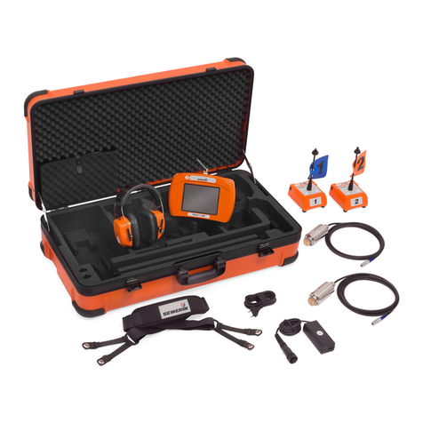
sewerin AQUAPHON A 50 User manual

17.07.2017 a – 107489 – en
AQUAPHON®
A 50 receiver
Operating instructions

A 50 receiver
Arrow keys
●Up key
Fig. 1: A 50 receiver viewed from various angles
●Down key
Activation key
Display
Filter key
Menu key
Enter key
Belt clip
Headphone socket
Microphone socket
Charging socket
Connectors

A 50 receiver
Fig. 2: Display with main view
Battery symbol for receiver
Current noise level (bar)
Current minimum noise level (marker)
Current minimum noise level
Minimum noise level
●last
●last but one
Filter level
Battery symbol for wireless head-
phones
Hearing protection level
Volume

Information about this document
Warnings and notes in this document mean the following:
AWARNING!
Risk of personal injury. Could result in serious injury or
death.
ACAUTION!
Risk of personal injury. Could result in injury or pose a risk
to health.
NOTICE!
Risk of damage to property.
Note:
Tips and important information.
Numbered lists (numbers, letters) are used for:
●Instructions that must be followed in a certain order
Lists with bullet points (point, dash) are used for:
●Lists
●Instructions that only involve one step
Numbers between forward slashes /.../ refer to the referenced doc-
uments.

Contents│ I
1 Introduction .............................................................................1
1.1 Warranty....................................................................................1
1.2 Purpose.....................................................................................2
1.3 Intended use .............................................................................2
1.4 General safety information ........................................................3
2 AQUAPHON system................................................................4
2.1 General information regarding the system ................................4
2.2 Hearing protection.....................................................................4
2.3 System components..................................................................5
2.3.1 Overview ................................................................................5
2.3.2 A 50 receiver ..........................................................................6
2.3.2.1 Setup...................................................................................6
2.3.2.2 Carrying options..................................................................7
2.3.2.3 Activation key operating modes ..........................................8
2.3.2.4 Noise level display ..............................................................8
2.3.2.5 Power supply.....................................................................10
2.3.3 Microphones.........................................................................10
3 Using the system ..................................................................13
3.1 Preparing the system ..............................................................13
3.2 Switching on the system .........................................................13
3.2.1 A 50 receiver only.................................................................13
3.2.2 System with F8 wireless headphones..................................13
3.2.3 System with K3 headphones................................................14
3.3 Switchingothesystem..........................................................15
3.4 Starting and ending a measurement (listening to noises) .......15
3.5 Adjusting the volume...............................................................16
3.6 Adjustingthelters..................................................................17
4 Settings ..................................................................................19
4.1 Overview .................................................................................19
4.2 Backlight (LIGHT)....................................................................20
4.3 Operating mode (ACTIVATION) ..............................................21
4.4 Display rotation (DISPLAY) .....................................................22
4.5 Hearing protection (MUTE) .....................................................23
4.6 Hearing protection threshold (PROTECT) ..............................24
4.7 Factory settings (RESET) ......................................................26

II │Contents
5 Maintenance and error management ..................................27
5.1 Charging the batteries.............................................................27
5.2 Care ........................................................................................28
5.3 Maintenance............................................................................28
5.4 Solving problems.....................................................................29
5.4.1 Error message......................................................................29
5.4.2 Handling defective lithium-ion batteries ...............................29
5.4.2.1 Identifying a defective battery ...........................................30
5.4.2.2 Removing the battery from the A 50 receiver....................30
6 Appendix................................................................................32
6.1 Technical data .........................................................................32
6.1.1 A 50 receiver ........................................................................32
6.1.2 TS 50 test rod.......................................................................34
6.1.3 UM 50 universal microphone ...............................................35
6.2 Microphonecongurationoptions ...........................................36
6.3 A 50 receiver ...........................................................................37
6.3.1 Adjustablelters...................................................................37
6.3.1.1 Bandpass ..........................................................................37
6.3.1.2 Notchlter.........................................................................37
6.3.2 Factory settings....................................................................38
6.4 Accessories.............................................................................39
6.5 Declarations of conformity.......................................................40
6.6 Advice on disposal ..................................................................40
7 Index.......................................................................................41

1 Introduction│ 1
1 Introduction
1.1 Warranty
The following instructions must be complied with in order for any
warranty to be applicable regarding functionality and safe oper-
ation of this equipment.
●Read these operating instructions prior to operating the prod-
uct.
●Use the product only as intended.
●Repairs and maintenance must only be carried out by special-
ist technicians or other suitably trained personnel. Only spare
parts approved by Hermann Sewerin GmbH may be used
when performing repairs.
● Changesormodicationstothisproductmayonlybecarried
out with the approval of Hermann Sewerin GmbH.
●
Use only Hermann Sewerin GmbH accessories for the product.
Hermann Sewerin GmbH shall not be liable for damages result-
ing from the non-observance of this information. The warranty
conditions of the General Terms and Conditions (AGB) of Her-
mann Sewerin GmbH are not broadened by this information.
In addition to the warnings and other information in these Oper-
ating Instructions, always observe the generally applicable safety
and accident prevention regulations.
The manufacturer reserves the right to make technical changes.

2 │1Introduction
1.2 Purpose
The AQUAPHON system with A 50 receiver is intended for elec-
tro-acoustic water leak detection. The system can be used both
outdoors and inside buildings.
The following uses are possible:
●Preliminary detection
− atttings(e.g.hydrants,slidegates)
●Pinpointing leaks
−on paved surfaces (e.g. asphalt, concrete, paving)
−on unpaved surfaces (e.g. gravel, crushed rock, grass)
Note:
The descriptions in these operating instructions relate to the sys-
tem as delivered (factory settings). The manufacturer reserves
the right to make changes.
1.3 Intended use
The system is intended for professional industrial and commer-
cial use. The appropriate specialist knowledge is required to op-
erate the system.
Note:
If necessary, learn more about the principles of the technology
before commencing practical work with the system.
Thesystemmustonlybeusedfortheapplicationsspeciedin
section 1.2.

1 Introduction│ 3
1.4 General safety information
This product was manufactured in accordance with all binding
legal and safety regulations. It corresponds to the state of the
art and complies with conformity requirements. The product is
safe to operate when used in accordance with the instructions
provided.
However, if you handle the product improperly or not as intend-
ed, the product may present a risk to persons and property. For
this reason, observe the following safety information without fail.
Risk of personal injury (health risk)
●
Handle the components carefully and safely both during trans-
port and when working.
●Proceed with extreme caution in the vicinity of electrical lines.
Hazards for the product and other property
●Always handle the components carefully.
●Do not drop the components.
●Do not place the components in places where they are at risk
of falling.
●Before starting work, check that the components are in good
working order. Never use damaged or defective components.
●Ensure that no dirt or moisture gets into the connections on
the components.
●Always observe the permitted operating and storage temper-
atures.

4 │2AQUAPHONsystem
2 AQUAPHON system
2.1 General information regarding the system
In order to use the system for leak detection, a microphone must
be connected to the A 50 receiver. The microphone picks up
noises.
If you press the Activation key on the receiver, you can hear the
noises through the headphones. The playback volume is adjust-
able. The noises are not saved.
2.2 Hearing protection
The system features a hearing protection function which protects
the user from sudden loud sound interference. This type of sound
interference can occur if a vehicle drives past or if the touch mi-
crophoneslipsothecontactpoint.
Hearingprotectionisactivatedwhenthepredenedhearingpro-
tection threshold is exceeded. When the noise from the source
ofinterferenceceases,hearingprotectionswitchesoagainau-
tomatically.
The way in which hearing protection works depends on the set-
tings (section 4.5 on page 23).
Note:
Another way of protecting the hearing from loud noises is to set
the volume only as high as is absolutely necessary.

2AQUAPHONsystem│ 5
2.3 System components
2.3.1 Overview
The system has a modular construction. The main system com-
ponents are as follows:
●A 50 receiver, in the following product variants:
−with SDR1radio module
−without SDR radio module
●Headphones
−F8 wireless headphones (A 50 with SDR only)
−K3 headphones (wired)
●Microphones
−UM 50 universal microphone
−TS 50 test rod
The microphones have to be used in conjunction with acces-
sories.
●Accessories
−Probe tips and extensions, available in various lengths
−M 10 tripod
−RP 10 resonance plate
The system components can be carried and stored in a bag or
rucksack if required.
Additional accessories can be added to the system at any time.
Note:
Detailed information about the headphones can be found in the
associated operating instructions.
1Sewerin Digital Radio

6 │2AQUAPHONsystem
2.3.2 A 50 receiver
2.3.2.1 Setup
For overviews including all part names for the receiver, see the
frontcoverap(g.1).
Keys
The receiver has the following keys:
●Activation key For starting and ending a measurement
(listening to noises).
●Arrow keys
For adjusting the volume.
Forchangingsettingsandlterlimits.
●Filter key For switching between the main view
and the Filter view.
●Menu key For switching between the main view
and the Settings view.
●Enter key In the Filter and Settings views: For
selecting the variables to be set.

2AQUAPHONsystem│ 7
Connections
The receiver has the following connections:
●Charging socket For charging the rechargeable battery.
The following can be connected:
– M4 AC/DC adapter
or
– M4 vehicle cable
●Microphone socket For connecting a microphone.
The following can be connected:
– UM 50 universal microphone
or
– TS 50 test rod
●Headphone socket For connecting the K3 headphones.
Display rotation
The orientation of the display can be adjusted to the position in
which the receiver is used. If the receiver is rotated through 180°
about its longitudinal axis, the display rotates too. This function
ensures that the display remains easy to read, regardless of the
position in which the receiver is used.
Connectors
The EA carrying strap can be attached to the connectors.
2.3.2.2 Carrying options
The receiver can be carried as follows when in use:
●worn around the neck (with the EA carrying strap)
●clipped to the waistband (with the belt clip)
●held in the hand

8 │2AQUAPHONsystem
2.3.2.3 Activation key operating modes
There is a choice of two operating modes for the Activation key.
●Hold mode
The Activation key is held down for the desired duration of the
measurement.
●Toggle mode
TheActivationkeyispressedbrieytostartthemeasurement.
TheActivationkeyispressedbrieyagaintoendthemeas-
urement.
The operating mode is selected in the settings.
2.3.2.4 Noise level display
The following noise levels are shown simultaneously on the dis-
playinthemainview(g.3):
●Current noise level
●Minimum noise level
−current
−last
−last but one
Note:
If you switch from the main view to the Settings or Filter view,
the noise level display disappears.

2AQUAPHONsystem│ 9
Fig. 3: Graphical and numerical noise level display
Top: current noise level (bar) and
current minimum noise level (marker in bar)
Middle: current minimum noise level (here: 398)
Right: [1] last minimum noise level (here: 277) and
[2] last but one minimum noise level (here: 53)
Current noise level
The current noise level is always displayed as soon as the sys-
tem is ready for use. It is displayed in the form of a black bar.
Minimum noise level
The minimum noise level relates to an ongoing or completed
measurement.
●Current minimum noise level
The current minimum noise level is displayed in the middle of
the main view as a numerical value and as a marker in the bar.
●Last minimum noise level
When a measurement has been completed, what was until
then the current minimum noise level is displayed as the last
minimum noise level next to [1].
●Last but one minimum noise level
When the next measurement has been completed, the last
minimum noise level becomes the last but one minimum noise
level and is displayed next to [2].

10 │2AQUAPHONsystem
2.3.2.5 Power supply
The A 50 receiver is powered by a special, permanently installed
lithium-ion rechargeable battery.
Only SEWERIN service personnel or other authorised specialists
may replace the lithium-ion rechargeable battery.
However, in the event of a fault the lithium-ion rechargeable bat-
tery must be removed before shipping the device. Information
about handling faulty lithium-ion batteries can be found in sec-
tion 5.4.2 on page 29.
AWARNING! Risk of explosion due to short-circuit
Faulty lithium-ion rechargeable batteries can explode due
to internal short-circuit.
●
Components containing a faulty lithium-ion battery must
not be shipped.
Information about charging the rechargeable battery can be
found in section 5.1 on page 27.
2.3.3 Microphones
The following microphones are available:
●UM 50 universal microphone
●TS 50 test rod
The microphones can be used for both preliminary detection and
for pinpointing leaks. The suitability of a microphone for a particu-
lar use is very much dependent on the nature of the contact point.
Anoverviewofthecongurationoptionsforthemicrophonescan
be found in section 6.2 on page 36.
Themicrophoneshaveaxedcablewithwhichtheyarecon-
nected to the receiver.
The microphones must always be used in conjunction with suit-
able accessories.

2AQUAPHONsystem│ 11
UM 50 universal microphone
Fig. 4: UM 50 universal microphone with microphone protector
Suitable accessories:
●Probe tip, usually with extensions
●M 10 tripod
●M 10 contact adapter
ACAUTION!
The contact adapter for the UM 50 universal microphone
contains a strong magnet.
●Keep the contact adapter away from magnetic storage
media (e.g. hard drives, credit cards) and medical de-
vices (e.g. pacemakers, insulin pumps).
Microphone protector
The universal microphone comes with a rubberised protective
cover to protect the microphone from external damage.
Wind shield
The two-piece wind shield can protect the universal microphone
against exterior noise interference (sound insulation).
Usingthewindshieldonlymakessenseifthemicrophoneistted
with a protective cover and the tripod is used.

12 │2AQUAPHONsystem
TS 50 test rod
Fig. 5: TS 50 test rod
Suitable accessories:
●Probe tip, optionally with extensions
●RP 10 resonance plate, optionally with M 10 tripod
Safety information about handling the TS 50
●Handle the test rod carefully and safely both during transport
and when working.
Exercise particular caution if the probe tip is screwed onto the
test rod.
●Do not lean on the test rod.
●Never carry the test rod by its cable.

3 Using the system│ 13
3 Using the system
3.1 Preparing the system
A microphone must be selected and prepared for the intend-
ed use. The microphones can only be used in conjunction with
screwed-on accessories.
Anoverviewofthecongurationoptionsforthemicrophones
depending on the intended use can be found in section 6.2 on
page 36.
●Screw the appropriate accessory to the microphone.
SEWERIN recommends protecting the UM 50 universal micro-
phone from external damage. Before using the microphone for
thersttime,putontheprotectivecoversupplied.
3.2 Switching on the system
How the system is switched on depends on which headphones
are used.
3.2.1 A 50 receiver only
The A 50 receiver switches on automatically as soon as a micro-
phone (universal microphone or test rod) is connected.
3.2.2 System with F8 wireless headphones
When using the F8 wireless headphones the system is switched
on as follows:
1. Switch on the F8 wireless headphones.
2. Connect a microphone (universal microphone or test rod) to
the receiver by plugging the phone jack into the microphone
socket on the receiver.
The receiver switches on. A start screen appears on the dis-
play.
Thenthemainviewappears(g.6).Thesystemisready
for use once the small battery symbol for the wireless head-
phones is visible.

14 │3Usingthesystem
Fig. 6: System with F8 wireless headphones ready for use (battery sym-
bol for wireless headphones visible)
If the battery symbol for the wireless headphones does not
appear ...
●Check that the wireless headphones are switched on. Is the
green LED on?
●Check the power supply to the wireless headphones. Do the
batteries need recharging or replacing?
3.2.3 System with K3 headphones
When using the K3 headphones the system is switched on as
follows:
1. The K3 headphones must be used with the 3.5 mm phone
jack. Remove the adapter (6.3 mm) from the phone jack if
necessary.
2.
Connect the headphones to the receiver by plugging the
phone jack into the headphone socket on the receiver.
3. Connect a microphone (universal microphone or test rod) to
the receiver by plugging the phone jack into the microphone
socket on the receiver.
The receiver switches on. A start screen appears on the dis-
play.
Thenthemainviewappears(g.7).Thesystemisreadyfor
use.
Table of contents
Other sewerin Receiver manuals
Popular Receiver manuals by other brands
Sony
Sony ICF-SW1000T Service manual

PCB Piezotronics
PCB Piezotronics W352C67 Installation and operating manual

Hallicrafters
Hallicrafters S-120 owner's guide

Panasonic
Panasonic CT-32XF55 operating instructions
Harman Kardon
Harman Kardon AVR 510 owner's manual
TechNexion
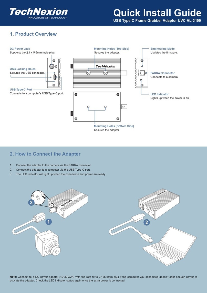
TechNexion UVC-VL-3100 Quick install guide

