sewerin SeCorr C 200 User manual

15.01.2020 a – 107613 – en
SeCorr®
C 200 receiver
RT 200 transmitter
Operating Instructions

C 200 receiver
Connectors
Fig. 1: C 200 receiver without aerial, front
Fig. 2: C 200 receiver, top view
LED
Light sensor
Touch screen
Connectors
Charging socket
USB port
Microphone socket
ON/OFF key
Aerial

RT 200 transmitter
Aerial with
knob and ag
Charging socket
Fig. 3: Transmitter 1 with blue ag and
transmitter 2 with orange ag
Bandpass display
Filter key
LED
Light key
Fig. 4: RT 200 transmitter without aerial, top view
Microphone socket
Fig. 5: RT 200 transmitter, back
Aerial connector

Information about this document
The warnings and notes in this document mean the following:
AWARNING!
Risk of personal injury. Could result in serious injury or death.
ACAUTION!
Risk of personal injury. Could result in injury or pose a risk
of health.
NOTICE!
Risk of damage to property.
Note:
Tips and important information.
Numbered lists (numbers, letters) are used for:
●Instructions that must be followed in a certain order
Lists with bullet points (point, dash) are used for:
●Lists
●Instructions that only involve one step

Contents │ I
1 Introduction .............................................................................1
1.1 Warranty....................................................................................1
1.2 Purpose.....................................................................................2
1.3 Intended use .............................................................................2
1.4 General safety information ........................................................3
1.5 Radio communication................................................................4
2 SeCorr system.........................................................................5
2.1 General information about the system ......................................5
2.2 System components..................................................................5
2.2.1 Overview ................................................................................5
2.2.2 C 200 receiver........................................................................6
2.2.2.1 Setup...................................................................................6
2.2.2.2 Carrying the system ............................................................8
2.2.2.3 Automatic power o ............................................................9
2.2.2.4 Main view ............................................................................9
2.2.2.5 How interference suppression works ................................15
2.2.3 RT 200 transmitter................................................................15
2.2.3.1 Setup.................................................................................16
2.2.3.2 Switching the transmitter on and o..................................17
2.2.4 Microphones.........................................................................18
2.2.4.1 UM 200 universal microphone ..........................................18
2.2.4.2 HY 200 hydrophone ..........................................................19
2.3 Switching on and o................................................................19
2.3.1 Receiver ...............................................................................19
2.3.2 Transmitter ...........................................................................20
2.4 Filter options (overview) ..........................................................20
2.5 Plug connection between microphone and RT 200
transmitter ...............................................................................20
2.6 Power supply to the components ............................................21
3 Using the system ..................................................................22
3.1 Preparing the system ..............................................................22
3.2 Measurement steps (overview) ...............................................22
3.3 Conguring the pipe sections..................................................22
3.3.1 Setting the number of pipe sections.....................................23
3.3.1.1 Adding a pipe section........................................................24
3.3.1.2 Deleting a pipe section......................................................24
3.3.2 Adjusting the pipe data.........................................................25

II │ Contents
3.4 Performing a measurement.....................................................25
3.4.1 Starting a measurement.......................................................26
3.4.1.1 Starting the measurement after conguring pipe sections 26
3.4.1.2 Continuing measurement..................................................26
3.4.1.3 Repeating a measurement................................................27
3.4.2 Stopping a measurement .....................................................27
3.4.3 Saving a measurement ........................................................27
3.4.3.1 Loading a saved measurement.........................................28
3.4.3.2 Deleting a saved measurement ........................................30
3.5 Optimising the correlation result using lters ..........................31
3.5.1 Filter menu (overview)..........................................................31
3.5.1.1 Frequency graph...............................................................33
3.5.1.2 Correlation curve...............................................................34
3.5.1.3 Quality of peak ..................................................................34
3.5.2 Selecting and adjusting lters ..............................................34
3.5.2.1 Selecting automatically calculated lters...........................35
3.5.2.2 Manually adjusting lters...................................................35
3.5.2.3 Applying the lters (exiting the Filter menu)......................38
3.6 Plausibility check.....................................................................38
3.6.1 Moving the marker ...............................................................38
3.6.2 Hide peak .............................................................................39
3.6.3 Sound velocity measurement...............................................40
3.6.3.1 Articial leak outside of the measuring section .................41
3.6.3.2 Articial leak within the measuring section........................41
3.7 Listening to noises ..................................................................42
3.7.1 Information about the radio connection during listening.......42
3.7.2 Transmitter menu (overview)................................................42
3.7.3 Adjusting the volume............................................................44
3.7.4 Selecting a transmitter .........................................................45
3.8 Microphone function for acoustic leak detection .....................45
3.8.1 Microphone menu (overview)...............................................46
3.8.2 Performing a noise measurement ........................................47
3.9 Locking and unlocking the display ..........................................48
4 Settings ..................................................................................49
4.1 Overview .................................................................................49
4.2 Setting actions.........................................................................49
4.2.1 Selecting ..............................................................................50
4.2.2 Enabling/disabling ................................................................50
4.2.3 Setting a value .....................................................................50
4.3 Settings in the Measurement menu ........................................52

Contents │ III
4.3.1 General ................................................................................53
4.3.1.1 Units..................................................................................53
4.3.1.2 Interference suppression...................................................53
4.3.1.3 Correlation curve...............................................................54
4.3.1.4 Blocking lter.....................................................................54
4.3.2 Filter basis............................................................................54
4.3.2.1 Coherence.........................................................................55
4.3.2.2 Cross spectrum.................................................................55
4.3.2.3 Spectrum 1 or Spectrum 2 ................................................55
4.3.2.4 Sound velocity...................................................................55
4.3.3 Pipe data (Default) ...............................................................56
4.3.3.1 Length ...............................................................................56
4.3.3.2 Material .............................................................................56
4.3.3.3 Diameter............................................................................56
4.3.3.4 Sound velocity...................................................................56
4.4 Settings in the Device menu ...................................................56
4.4.1 General ................................................................................58
4.4.1.1 Switching o the device ....................................................58
4.4.1.2 Switching o the backlight.................................................58
4.4.1.3 Automatic brightness.........................................................59
4.4.1.4 Brightness .........................................................................59
4.4.2 Time/Date.............................................................................59
4.4.2.1 Time ..................................................................................59
4.4.2.2 Date...................................................................................59
4.4.3 Region..................................................................................60
4.4.3.1 Date format .......................................................................60
4.4.3.2 Time format .......................................................................60
4.4.3.3 Language ..........................................................................60
4.4.4 Service .................................................................................60
4.4.4.1 Information ........................................................................60
4.4.4.2 Calibration.........................................................................61
5 Maintenance ..........................................................................62
5.1 Charging the batteries.............................................................62
5.1.1 Charging the batteries in the case .......................................62
5.1.2 Charging batteries using the AC/DC adapter or vehicle
cable.....................................................................................63
5.2 Handling faulty lithium-ion rechargeable batteries ..................64
5.2.1 Identifying faulty batteries ....................................................64
5.2.2 Removing the batteries from the C 200 receiver..................65
5.2.3 Removing the battery from the RT 200 transmitter ..............66
5.3 Calibrating the touch screen ...................................................67

IV │ Contents
5.4 Care ........................................................................................68
5.5 Maintenance............................................................................68
6 Appendix................................................................................69
6.1 Technical data .........................................................................69
6.1.1 C 200 receiver......................................................................69
6.1.2 RT 200 transmitter................................................................71
6.1.3 UM 200 universal microphone ............................................73
6.1.4 HY 200 hydrophone .............................................................74
6.2 Symbols on the touch screen of the C 200 receiver ...............75
6.3 Signicance of LED signals.....................................................77
6.3.1 C 200 receiver......................................................................77
6.3.2 RT 200 transmitter................................................................78
6.4 Troubleshooting.......................................................................79
6.5 Accessories.............................................................................79
6.6 Declaration of conformity ........................................................79
6.7 Licences in the EEA ................................................................80
6.8 Note about the rmware (open source software)....................81
6.9 Advice on disposal ..................................................................81
7 Index.......................................................................................82

1 Introduction │ 1
1 Introduction
1.1 Warranty
The following instructions must be complied with in order for any
warranty to be applicable regarding functionality and safe oper-
ation of this equipment.
●Read these operating instructions prior to operating the prod-
uct.
●Use the product only as intended.
●Repairs and maintenance must only be carried out by special-
ist technicians or other suitably trained personnel. Only spare
parts approved by Hermann Sewerin GmbH may be used
when performing repairs.
● Changes or modications to this product may only be carried
out with the approval of Hermann Sewerin GmbH.
●
Use only Hermann Sewerin GmbH accessories for the product.
Hermann Sewerin GmbH shall not be liable for damages result-
ing from the non-observance of this information. The warranty
conditions of the General Terms and Conditions (AGB) of Her-
mann Sewerin GmbH are not broadened by this information.
In addition to the warnings and other information in these Oper-
ating Instructions, always observe the generally applicable safety
and accident prevention regulations.
The manufacturer reserves the right to make technical changes.

2 │ 1 Introduction
1.2 Purpose
SeCorr is a system used for correlation.
The SeCorr system can be used for:
●Detecting leaks in water pipes
Note:
All descriptions in these operating instructions refer to the system
as delivered (factory settings). The operating instructions apply
to the C 200 receiver with rmware version 2.x and higher. The
manufacturer reserves the right to make changes.
1.3 Intended use
The SeCorr system is intended for professional industrial and
commercial use. The appropriate specialist knowledge is re-
quired to operate the system.
Note:
If necessary, learn more about the principles of the technology
before commencing practical work with the system.
The system must only be used for the applications specied in
section 1.2.

1 Introduction │ 3
1.4 General safety information
This product was manufactured in keeping with all binding legal
and safety regulations. It corresponds to the state of the art and
complies with conformity requirements. The product is safe to
operate when used in accordance with the instructions provided.
However, if you handle the product improperly or not as intend-
ed, the product may present a risk to persons and property. For
this reason, observe the following safety information without fail.
Risk of personal injury (health risk)
●
Handle the components carefully and safely both during trans-
port and when working.
● Proceed with extreme caution in the vicinity of electrical lines.
Hazards for the product and other property
●Always handle the components carefully.
●Do not drop the components.
●Do not place the components in places where they are at risk
of falling.
●The aerials of the C 200 receiver and RT 200 transmitter must
not be damaged.
−Never bend, kink or cut the aerial.
−Never carry the C 200 receiver by its aerial.
●Before starting work, check that the components are in good
working order. Never use damaged or defective components.
●Ensure that no dirt or moisture gets into the connections on
the components.
●Always observe the permitted operating and storage temper-
atures.

4 │ 1 Introduction
1.5 Radio communication
The SeCorr system uses the following data transmission tech-
nologies:
● Near-eld radio
●SDR (Sewerin Digital Radio)
Near-eld radio
The transmitter and receiver communicate by near-eld radio.
The RT 200 transmitter is classed as radio equipment according
to EU Directive 2014/53/EU. It may, therefore, be subject to some
use restrictions.
Note:
Users of the SeCorr system are responsible for ensuring compli-
ance with local country regulations regarding the registration and
use of radio equipment. This applies even if there is an explicit
licence for a country.
You can nd a list of the countries of the European Econom-
ic Area (EEA) where this equipment is licensed for use in sec-
tion 6.7 on page 80.
Note:
Radio systems that use the same frequencies can interfere with
each other.
● Switch o the transmitters when not in use.
SDR radio
Receivers and wireless headphones communicate by bidirection-
al SDR (SDR: Sewerin Digital Radio). SDR is only used when
listening to noises.
For more detailed information about the special features of this
radio connection, please refer to section 3.7.1 on page 42.

2 SeCorr system │ 5
2 SeCorr system
2.1 General information about the system
The SeCorr system works using the correlation method, whereby
measurements are taken at two ttings (e.g. slide gate, hydrant)
at the same time. Highly sensitive microphones record the nois-
es at the ttings. The two microphones are each connected to a
radio transmitter. The radio transmitters transmit the signals to a
receiver – the correlator. The correlator determines the run time
dierence between the signals, i.e. the time lag between the nois-
es reaching the two measuring points. This is then used, together
with the pipe data, by the correlator to calculate the leak position.
The advantage of the correlation method is that the leak position
is determined independently of the hearing and experience of
the user.
The system features a function which can also locate leaks
acoustically if there is no suitable technology available specif-
ically for pinpointing or prelocation.
2.2 System components
2.2.1 Overview
SeCorr is a modular system. The main system components are
as follows:
●C 200 receiver (correlator)
●2 RT 200 transmitters (1 pair)
− Transmitter 1 with blue ag
− Transmitter 2 with orange ag
●2 microphones, e.g.:
−UM 200 universal microphone
OR
−HY 200 hydrophone
One microphone is required for each RT 200 transmitter. The
same type of microphone must always be used for the two
transmitters.

6 │ 2 SeCorr system
●F8 wireless headphones (optional)
●AC 200 SK 4 case
The system can be transported and stored in the case. The
batteries for the components C 200, RT 200 and F8 can be si-
multaneously charged in the case using the AC/DC adapter L.
Accessories can be added to the system at any time.
Note:
Information about F8 wireless headphones can be found in the
relevant operating instructions.
2.2.2 C 200 receiver
The C 200 receiver receives data from the RT 200 transmitter.
The receiver calculates the leak position from the run time dier-
ence between the signals of the two receivers.
The C 200 receiver is also known as a correlator.
2.2.2.1 Setup
Overviews with the names of all the parts of the receiver can be
found inside the front cover (g. 1 and g. 2).
Its symmetrical housing means that it can be operated by both
right-handed and left-handed users with ease.
Touch screen
The receiver features a touch screen. Certain areas of the touch
screen are touch-sensitive. Actions are performed by touching
these areas (buttons).
All of the buttons have a thick, dark grey outline.
Only your nger or a touch pen should be used to operate the
touch screen.
●
Always touch the buttons briey without exerting too much
pressure.

2 SeCorr system │ 7
NOTICE! Risk of damage
The surface of the touch screen is sensitive.
●Do not use any hard or sharp objects (e.g. pens) to operate
the screen.
●Protect the touch screen against aggressive substances (e.g.
acidic or abrasive detergents).
An overview with the symbols that might appear on the touch
screen can be found in section 6.2 on page 75.
Light sensor
The light sensor analyses the ambient lighting conditions.
If the automatic brightness setting is enabled, the light sensor
always adjusts the brightness of the touch screen to the ambient
lighting conditions.
Information about the automatic brightness setting can be found
in section 4.4.1.3 on page 59.
ON/OFF key
The ON/OFF key has the following functions:
● Switching the receiver on and o
●Locking and unlocking the display
LED
The LED indicates the operating status.
Information about what the LED signals mean can be found in
section 6.3.1 on page 77.
Aerial
When using the receiver, the aerial must be pointing upwards
(g. 6). It can be folded down for storage in the case.

8 │ 2 SeCorr system
Fig. 6: Receiver in its normal position of use
The aerial is pointing upwards.
Ports
The receiver features the following ports:
●Charging socket
For charging the rechargeable battery.
●Microphone socket
For connecting a microphone, e.g. UM 200 universal micro-
phone.
●USB port
For connecting to a computer.
Connectors
Carrying systems (Vario, lap belt), the triangle 200 carrying strap
or a hand loop can be attached to the connectors.
The connectors are parts of the quick-release fasteners.
2.2.2.2 Carrying the system
The receiver is usually carried in front of the body so that the user
looks diagonally down at the touch screen.
SEWERIN recommends: Use a carrying system for locating op-
erations. The carrying system prevents you from tiring during
work. It also reduces the possibility of radio interference. Ra-
dio interference can occur if the user accidentally covers certain
components in the receiver.
2 SeCorr system │ 9
2.2.2.3 Automatic power o
The power supply to the receiver is designed in such a way that
a fully charged battery will allow one full day‘s work without in-
terruption. However, it is still recommended to conserve energy
whilst working.
The receiver therefore oers the following automatic power-o
options:
●Switching o the device
The receiver switches o if it is not operated for a specied
period of time. It must be switched back on again when you
want to continue work.
●Switching o the backlight
The receiver backlight switches o if it is not operated for a
specied period of time. The receiver remains switched on.
If and when the automatic power o is activated depends on the
settings (Device menu > General > Switch o device or Switch
o backlight).
2.2.2.4 Main view
The touch screen of the receiver displays the main view when
the system is ready for use.
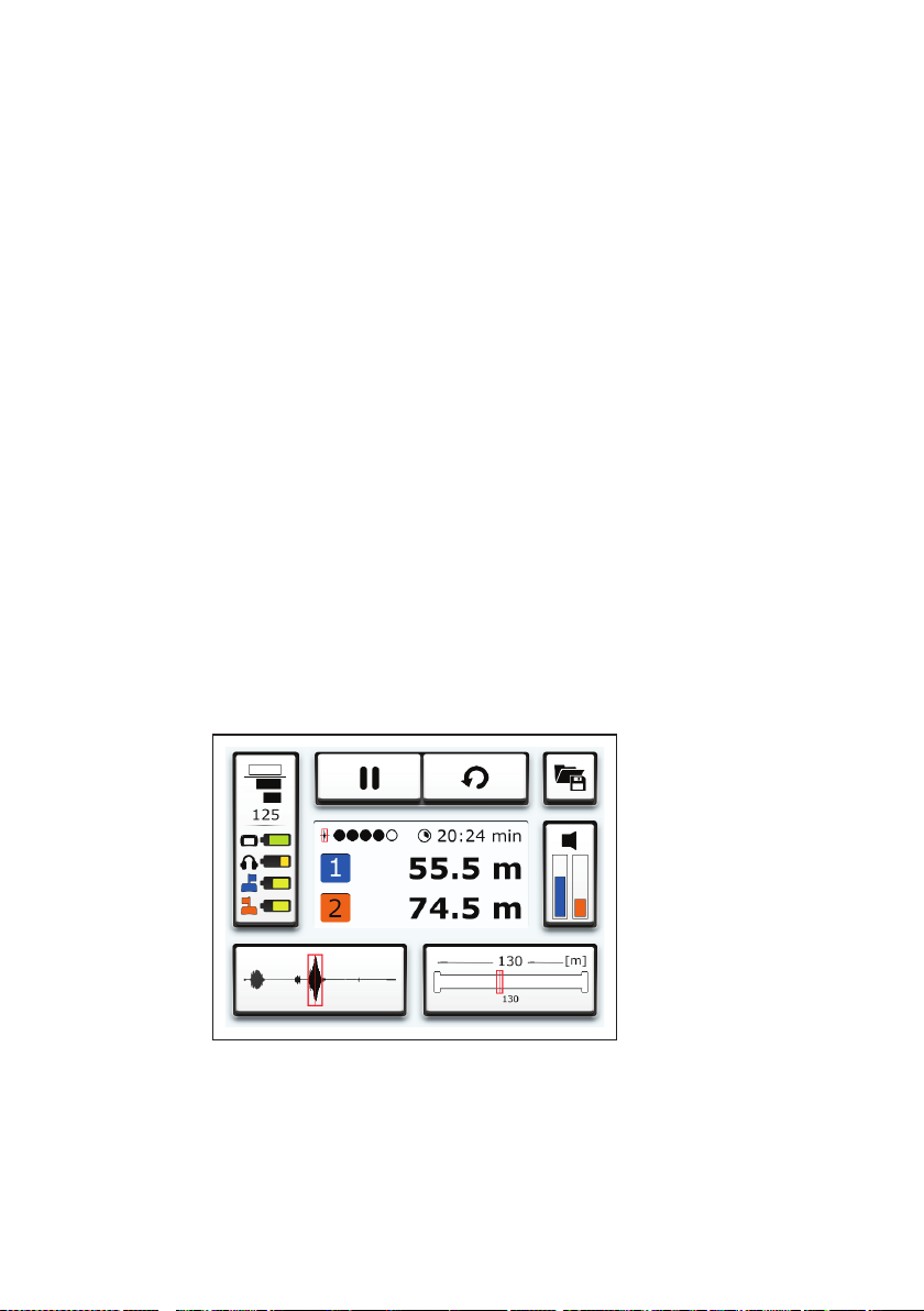
Fig. 7: Main view

10 │ 2 SeCorr system
Fig. 8: Results display (detail of main view)
The following is shown in the centre of the main view (g. 8):
●Leak position
Distance of leak from transmitter 1 and transmitter 2
●Quality of peak
●Duration of measurement
The main view also contains the following buttons:
●Measurement
●File
●Transmitter
●Pipe sections
●Filter
●Settings
These buttons can be used to open submenus. Most of the but-
tons also display information. The information displayed depends
on the situation.
Measurement
The Measurement button is divided into dierent sections. The
appearance of the Measurement button depends on what the
program is doing (g. 9).
●Start measurement button
OR
Stop measurement button
●Reset button

2 SeCorr system │ 11
Fig. 9: Measurement button at various stages of the program
Top image: A measurement can be started.
Centre image: A measurement can be stopped.
Bottom image: The calculation data must be reset
before a measurement can be started.
For more detailed information on performing measurements,
please refer to section 3.4 on page 25.
File
The File menu is opened by pressing the File button. The follow-
ing actions can be performed in this menu:
●Save measurement
●Load saved measurement
●Delete saved measurement
Fig. 10: File button
For information about saving, loading and deleting measure-
ments, please refer to section 3.4.3 on page 27.
Transmitter
The Transmitter button displays the following information:
●Current noise level of the transmitters
−Left: Transmitter 1 (blue)
−Right: Transmitter 2 (orange)

12 │ 2 SeCorr system
Fig. 11: Transmitter button
The Transmitter menu is opened by pressing the Transmitter
button. The following settings can be made in this menu:
●Transmitters from which noises can be heard through head-
phones
●Volume of noise on headphones
Information about the two transmitters is also displayed.
For more detailed information about the Transmitter menu and
listening to noises, please refer to section 3.7 on page 42.
Pipe sections
The Pipe sections button displays the following information:
●Total length of measuring section
●Number and length of pipe sections
●Marker
Indicates the leak position in the pipe section concerned.
Other manuals for SeCorr C 200
1
This manual suits for next models
1
Table of contents
Other sewerin Receiver manuals


