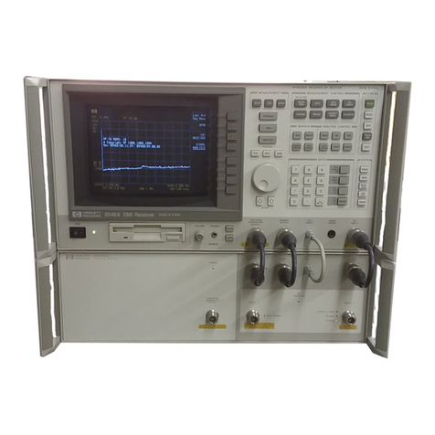
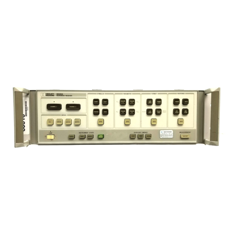
HP 8542E User manual

About this Manual
We’ve added this manual to the Agilent website in an effort to help you support
your product. This manual is the best copy we could find; it may be incomplete
or contain dated information. If we find a more recent copy in the future, we will
add it to the Agilent website.
Support for Your Product
Agilent no longer sells or supports this product. Our service centers may be able
to perform calibration if no repair parts are needed, but no other support from
Agilent is available. You will find any other available product information on the
Agilent Test & Measurement website, www.tm.agilent.com.
HP References in this Manual
This manual may contain references to HP or Hewlett-Packard. Please note that
Hewlett-Packard's former test and measurement, semiconductor products and
chemical analysis businesses are now part of Agilent Technologies. We have
made no changes to this manual copy. In other documentation, to reduce
potential confusion, the only change to product numbers and names has been in
the company name prefix: where a product number/name was HP XXXX the
current name/number is now Agilent XXXX. For example, model number
HP8648A is now model number Agilent 8648A.
Advanced Test Equipment Rentals
www.atecorp.com 800-404-ATEC (2832)
®
E
s
t
a
b
l
i
s
h
e
d
1
9
8
1

User's Guide
EMI Receiver Series
HP 8542E/HP 8546A
EMI Receiver
HP 85422E/HP 85462A
Receiver RF Section
ABCDE
HP Part No. 5962-5081
Printed in USA August 1994

Notice
The information contained in this document is subject to change
without notice.
Hewlett-P
ackard makes no warranty of any kind with regard to this
material, including but not limited to, the implied warranties of
merchantability and tness for aparticular purpose. Hewlett-Packard
shall not be liable for errors contained herein or for incidental
or consequential damages in connection with the furnishing,
performance, or use of this material.
c
Copyright Hewlett-Packard Company 1994
All Rights Reserved. Reproduction, adaptation, or translation without
prior written permission is prohibited, except as allowed under the
copyright laws.
1400 Fountaingrove Parkway, Santa Rosa CA, 95403-1799, USA

Certication
Hewlett-P
ackard Company certies that this product met its
published specications at the time of shipment from the factory.
Hewlett-P
ackard further certies that its calibration measurements
are traceable to the United States National Institute of Standards and
T
echnology, to the extent allowed by the Institute's calibration facility,
and to the calibration facilities of other International Standards
Organization members.
Regulatory Information
Regulatory information is located in the
EMI Receiver Series Reference
manual at the end of Chapter 1, \Specications and Characteristics."
Warranty
This Hewlett-Packard instrument product is warranted against defects
in material and workmanship for a period of one year from date of
shipment. During the warranty period, Hewlett-Packard Company
will, at its option, either repair or replace products which prove to be
defective.
F
or warranty service or repair
,this product must be returned to a
service facility designated by Hewlett-P
ackard. Buyer shall prepay
shipping charges to Hewlett-P
ackard and Hewlett-P
ackard shall pay
shipping charges to return the product to Buyer
.However
,Buyer shall
pay all shipping charges
,duties
,and taxes for products returned to
Hewlett-P
ackard from another country
.
Hewlett-P
ackard warrants that its software and rmware designated
by Hewlett-P
ackard for use with an instrument will execute
its programming instructions when properly installed on that
instrument. Hewlett-P
ackard does not warrant that the operation
of the instrument, or software, or rmware will be uninterrupted or
error-free.
Limitation of Warranty
The foregoing warranty shall not apply to defects resulting from
improper or inadequate maintenance by Buyer, Buyer-supplied
software or interfacing, unauthorized modication or misuse,
operation outside of the environmental specications for the
product, or improper site preparation or maintenance
.
NO OTHER W
ARRANTY IS EXPRESSED OR IMPLIED
.
HEWLETT-PACKARD SPECIFICALLY DISCLAIMS THE IMPLIED
WARRANTIES OF MERCHANTABILITY AND FITNESS FOR A
PARTICULAR PURPOSE.
Exclusive Remedies
THE REMEDIES PROVIDED HEREIN ARE BUYER'S SOLE AND
EXCLUSIVE REMEDIES. HEWLETT-PACKARD SHALL NOT BE
LIABLE FOR ANY DIRECT, INDIRECT, SPECIAL, INCIDENTAL, OR
CONSEQUENTIAL DAMAGES, WHETHER BASED ON CONTRACT,
TORT, OR ANY OTHER LEGAL THEORY.
iii

Assistance
Product maintenance agreements and other customer assistance
agreements are available for Hewlett-P
ackard products.For any
assistance
,contact your nearest Hewlett-Packard Sales and Service
Oce
.
Compliance
This instrument has been designed and tested in accordance with
IEC Publication 348, Safety Requirements for Electronic Measuring
Apparatus, and has been supplied in a safe condition. The instruction
documentation contains information and warnings which must be
followed by the user to ensure safe operation and to maintain the
instrument in a safe condition.
Safety Notes
The following safety notes are used throughout this manual.
Familiarize yourself with each of the notes and its meaning before
operating this instrument.
WARNING
Warning denotes a hazard. It calls attention to a procedure
which, if not correctly performed or adhered to, could result in
injury or loss of life.Do
not
proceed beyond a warning note until
the indicated conditions are fully understood and met.
CA
UTION
Caution denotes ahazard. It calls attention to a procedure that, if
not correctly performed or adhered to, would result in damage to or
destruction of the instrument. Do
not
proceed beyond a caution sign
until the indicated conditions are fully understood and met.
iv

General Safety Considerations
WARNING
No operator serviceable parts inside. Refer servicing to
qualied personnel. To prevent electrical shock, do not remove
covers.
If this instrument is not used as specied, the protection
provided by the equipment may be impaired. This instrument
must be used in a normal condition (in which all means for
protection are intact) only.
For continued protection against re hazard, replace line fuse
only with same type and rating ([F 5A/250V]). The use of other
fuses or material is prohibited.
CAUTION
Before switching on this instrument, make sure that the line voltage
selector switch is set to the voltage of the power supply and the
correct fuse is installed.
Always use the three-prong ac power cord supplied with this
instrument. Failure to ensure adequate earth grounding by not
using this cord may cause instrument damage.
Only clean the instrument cabinet using adamp cloth.x
L
The instruction documentation symbol. The product is
marked with this symbol when it is necessary for the
user to refer to the instructions in the documentation.
CE The CE mark is a registered trademark of the European
Community
.(If accompanied by a year, it is when the
design was proven.)
ISM1-A This is asymbol of an Industrial Scientic and Medical
Group 1 Class A product.
CSA The CSA mark is a registered trademark of the Canadian
Standards Association.
Manual Conventions
4
Front-Panel Key
5
This represents a key physically located on the
instrument.
NNNNNNNNNNNNNNNNNNNNNNN
Softkey
This indicates a \softkey," a key whose label is
determined by the rmware of the instrument.
Screen Text
This indicates text displayed on the instrument's
screen.
v

EMI Receiver Series Documentation Description
The following documents are provided with either the HP 8542E/
HP 8546A EMI receiver or the HP 85422E/HP 85462A receiver RF
section.
Installation and Verication
provides information for installing
your instrument, verifying instrument operation, and customer
support.
User's Guide
describes instrument features and how to make
measurements with your EMI receiver or receiver RF section.
Reference
provides specications and characteristics, menu maps,
error messages, and key descriptions.
Programmer's Guide
provides information on remote control
instrument conguration, creating programs, and parameters for
each of the programming commands available.
vi

Contents
1. Getting Started
What You'll Learn in This Chapter . . . . . . . . . . . 1-1
Introducing the EMI Receiver . . . . . . . . . . . . 1-1
Getting Acquainted with the EMI Receiver . . . . . . . 1-3
Front-Panel Features ................ 1-3
Data Controls ................... 1-6
Number/Units Keypad .............. 1-6
Knob ...................... 1-6
Step Keys .... .. .. .. .. .. .. .. .. 1-7
HOLD Key . . . . . . . . . . . . . . . . . . . . 1-7
Rear-P
anel F
eatures ................ 1-7
Screen Annotation .................. 1-10
Receiver RF Section Annotation . . . . . . . . . . . 1-11
Menu and Softkey Overview ............. 1-12
Disk Drive ...................... 1-13
Receiver RF Section Battery Information . . . . . . . . 1-14
2. Calibration
What You'll Learn in this Chapter ........... 2-1
Improving Accuracy .... .. .. .. .. .. .. 2-1
When is Self-Calibration Needed? .......... 2-2
Warm-UpTime .. .. .. .. .. .. . .. .. .. 2-2
Calibrating the EMI Receiver ......... .. . 2-3
Using
NNNNNNNNNNNNNNNNNNNNNNNNNNNNN
CAL FETCH
.... .. .. .. .. .. .. 2-3
V
erifying the Receiver's Calibration ..... .. . 2-3
Using
NNNNNNNNNNNNNNNNNNNNNNN
CAL ALL
.... .. .. .. .. .. .. .. 2-4
Using
NNNNNNNNNNNNNNNNNNNNNNNNNNNNN
CAL STORE
................ 2-5
Interrupting calibration . . . . . . . . . . . . . . 2-5
Using the AutoCal Function . . . . . . . . . . . . . 2-6
Setting the Receiver's Clock . . . . . . . . . . . . 2-6
Setting A
utoCal Time ............... 2-6
Performing a P
artial Calibration . . . . . . . . . . . 2-7
Performing the Tracking Generator Self-Calibration
Routine . . . . . . . . . . . . . . . . . . . . . 2-8
Performing the YIG-Tuned Filter Self-Calibration
Routine . . . . . . . . . . . . . . . . . . . . . 2-8
Calibrating the Receiver RF Section as a Standalone
Instrument ................... 2-9
Contents-1

3. Making Compliance Measurements
What You'll Learn in This Chapter . . . . . . . . . . . 3-1
Introducing the SETUP, TEST, and OUTPUT Keys . . . . 3-2
Setting Up a Measurement Using the SETUP Key . . . . 3-2
Using Standard Congurations . . . . . . . . . . . . 3-2
Customizing the Standard Congurations . . . . . . . 3-3
Modifying Start and Stop Frequencies ....... 3-3
Modifying Reference Level and Input Attenuation . 3-3
Modifying IF and Averaging Bandwidths . . . . . . 3-4
Selecting the Active Detector .... .. .. .. . 3-4
Selecting the Measured Detectors .... .. .. . 3-5
Measuring Detector Dwell Times ......... . 3-6
Controlling the Preamplier . . . . . . . . . . . . 3-6
Controlling Autoranging.... .. .. .. .. .. 3-7
Loading User-Dened Congurations from a Disk . . . 3-8
UsingLimitLines.................. 3-8
Loading a Limit Line from the Disk .. .. . .. . 3-9
Using Amplitude Correction F
actors .... .. .. . 3-10
Loading an Amplitude Correction Factor File from a
Disk ..................... 3-11
Activating the Windows Display Format ....... 3-12
Making a Measurement .... .. .. .. .. .. .. 3-14
Tuning the Receiver .............. .. 3-14
Using the Marker to Tune the Receiver ....... 3-15
Using the Measure at Marker Function ........ 3-16
Creating aReport .............. .. .. . 3-19
Conguring aPrinter ................ 3-19
Conguring and Generating aReport . . . . . . . . . 3-20
4. List-Based Measurements
A
dding Signals to the List . . . . . . . . . . . . . . 4-3
Viewing the Signal List .... .. .. .. .. .. . 4-5
Sorting the Signal List .... .. .. .. .. .. . 4-6
Deleting Signals From the List . . . . . . . . . . . . 4-7
Marking Signals .... .. .. .. .. .. .. .. 4-8
Remeasuring Signals ................ 4-9
Saving Signal Lists ...... .. .. .. .. .. . 4-10
Recalling Signal Lists .... .. .. .. .. .. .. 4-10
Graphing Signal Lists . . . . . . . . . . . . . . . . 4-11
Saving Signal Lists Graphs ............. 4-12
5. Stepped Measurements
Performing a Stepped Measurement ......... 5-1
Selecting a Detector and Setting a Dwell Time .. . 5-3
Using the Marker . . . . . . . . . . . . . . . . . 5-4
Adding Data to the Signal List Table ........ 5-5
Changing the Frequency Step . . . . . . . . . . . 5-5
Restarting and Stopping the Measurement ..... 5-5
Using Logarithmic and Linear Steps .... .. .. . 5-7
Contents-2

6. Making EMI Diagnostic Measurements
What You'll Learn in This Chapter . . . . . . . . . . . 6-1
Resolving Signals of Equal Amplitude .. .. .. .. . 6-2
Resolving Small Signals Hidden by Large Signals .... 6-5
Increasing the Frequency Readout Resolution ..... 6-8
Decreasing the Frequency Span . . . . . . . . . . . . 6-10
Peaking Signal Amplitude with Preselector Peak .... 6-11
Tracking Unstable Signals . . . . . . . . . . . . . . . 6-13
Using the Marker Track Function .... .. .. .. 6-13
Using Maximum-Hold and Minimum-Hold ...... 6-15
Comparing Signals Using Delta Markers .... .. .. 6-18
Measuring Dierences Between Two Signals ..... 6-18
Measuring Dierences Between Signals On Screen and
O Screen ................... 6-19
Measuring Low-Level Signals .... .. .. .. .. . 6-22
Reducing Input Attenuation . . . . . . . . . . . . . 6-22
Reducing IF Bandwidth . . . . . . . . . . . . . . . 6-25
Reducing A
veraging Bandwidth ........... 6-26
Using Video Averaging ............... 6-27
Testing for Distortion Using the Linearity Check .... 6-30
Measuring Small Signals in the Presence of a Large
Ambient Signal .... .. .. .. .. .. .. . 6-30
Using Linearity Check .............. . 6-33
Demodulating and Listening to an AM or FM Signal ...6-36
7. Making Other Measurements
What Y
ou'll Learn in This Chapter ......... .. 7-1
Stimulus-Response Measurements ...... .. .. . 7-2
What Are Stimulus-Response Measurements? .... . 7-2
Using the Receiver With the Internal Tracking
Generator ....... .. .. . .. .. .. .. 7-2
Stepping Through the Measurement ......... 7-3
Tracking Generator Unleveled Condition . . . . . . . 7-7
Measuring Amplitude Modulation with the Fast Fourier
Transform Function . . . . . . . . . . . . . . . . 7-8
Measuring the Sidebands on a Signal . . . . . . . . . 7-8
Repeating the test .... .. .. .. .. .. .. 7-12
Measuring 3 dB and 6 dB Bandwidth . . . . . . . . . 7-13
Measuring 99% Power Bandwidth .......... 7-14
Measuring Percent AM Modulation . . . . . . . . . . 7-15
Measuring Amplitude and Frequency Dierence ... 7-16
Making 3rd Order Measurements .. .. .. .. .. 7-18
8. Limit Lines
Using Receiver Limit Lines .............. 8-2
Creating, Editing, or Viewing a Limit Line . . . . . . 8-2
Editing an Existing Limit Line . . . . . . . . . . . . 8-6
Dening a Limit Margin . . . . . . . . . . . . . . . 8-7
Activating Limit-Line Testing ............ 8-8
Saving or Recalling Limit-Line Tables .. .. .. .. 8-8
Saving a Limit-Line Table .... .. .. .. .. . 8-8
Recalling a Limit-Line Table.... .. .. .. .. 8-9
Viewing the Disk Catalog ............. 8-10
Using Signal Analyzer Limit Lines .. .. .. .. .. . 8-11
Creating, Editing or Viewing a Limit Line .... .. 8-11
Contents-3

Selecting Limit-Line Parameters.......... 8-12
Selecting the Amplitude Scale . . . . . . . . . . . 8-13
Selecting the Limit-Line Table Format .. .. .. .. 8-15
Activating Limit-Line Testing ............ 8-16
9. Amplitude Correction Functions
Creating, Editing, or Viewing the Amplitude-Correction
Tables ..................... 9-1
Activating Amplitude Correction .... .. .. .. 9-6
Saving or Recalling . . . . . . . . . . . . . . . . . 9-7
10. Windows
Learn About the Windows Display . . . . . . . . . . . 10-1
11. Saving, Recalling, and Outputting Data
Using a Floppy Disk ................. 11-1
F
ormatting the Disk ..... .. .. .. .. . .. 11-1
Filenames ........ .. .. .. .. .. .. . 11-2
DOSFilenames.................. 11-2
LIF Filenames . . .. .. .. .. .. .. .. .. 11-2
Available Operations ................ 11-2
Entering aPrex ............... .. . 11-3
Saving aTrace ................... 11-4
Recalling aTrace .................. 11-6
Saving and Recalling Data from Internal Memory ....11-9
Saving aState ................... 11-9
Recalling aState ..... .. .. .. .. .. .. . 11-9
Saving aTrace ..... .. .. .. .. .. .. .. 11-10
Recalling aTrace .................. 11-10
Protecting Data from Being Overwritten . . . . . . . . 11-11
How to Output Data ................. 11-12
Conguring aPrinter ................ 11-12
Conguring and Generating a Report . . . . . . . . . 11-13
12. Additional Features
What You'll Learn in This Chapter . . . . . . . . . . . 12-1
Signal Analyzer Emulation .............. 12-1
Demodulator . . . . . . . . . . . . . . . . . . . . . 12-2
TrackingGenerator.... .. .. .. .. .. .. .. 12-2
User-Denable Softkeys . . . . . . . . . . . . . . . . 12-5
Defaults ........
.............. 12-5
Programming.... .. .. .. .. .. .. .. .. 12-6
Resetting . . . . . . . . . . . . . . . . . . . . . . 12-6
External Keyboard .. .. .. .. .. .. .. .. .. 12-7
Installation . . . . . . . . . . . . . . . . . . . . . 12-7
Using the Template . . . . . . . . . . . . . . . . . 12-8
Entering Data Using the External Keyboard ..... 12-9
Entering Annotation .... .. .. .. .. .. . 12-9
Entering Programming Commands . . . . . . . . . 12-10
Entering a Screen Title .. .. .. .. .. .. .. 12-10
Entering a Prex . . . . . . . . . . . . . . . . . 12-11
Contents-4

13. Error Messages
Nonrecoverable System Errors ............ 13-14
14. Customer Support
If You Have a Problem .... .. .. .. .. .. .. 14-1
Calling HP Sales and Service Oces .......... 14-1
ChecktheBasics ..... .. .. .. .. .. .. .. 14-2
If Your EMI Receiver Does Not Turn On ....... 14-2
If the RF Filter Section Does Not Seem to be Working . 14-2
If the EMI Receiver Cannot Communicate Via HP-IB . 14-2
Verication of Proper Operation . . . . . . . . . . . 14-2
If the RF lter section Does Not P
ower O...... 14-2
Error Messages . . . . . . . . . . . . . . . . . . . 14-2
Additional Support Services . . . . . . . . . . . . . . 14-3
CompuServe ... .. . .. .. .. .. .. .. .. 14-3
FAX Support Line .. .. .. .. .. .. .. .. . 14-4
Returning the EMI Receiver for Service .... .. .. 14-5
P
ackage the EMI receiver for shipment ....... 14-5
Index
Contents-5

Figures
1-1. EMI Receiver . . . . . . . . . . . . . . . . . . . . 1-1
1-2. Front-Panel Feature Overview . . . . . . . . . . . . 1-3
1-3. Rear-Panel Feature Overview ............ 1-7
1-4. EMC Screen Annotation, Normal Operating Mode . . . 1-10
1-5. EMC Screen Annotation Using Windows . . . . . . . 1-11
1-6. Rear-Panel Battery Information Label ........ 1-14
3-1. Active Detector and Measured Detector Messages . . . 3-5
3-2. \
PREAMP ON
" and \
AUTORANGE ON
" Messages .. .. . 3-7
3-3. Using the Measure at Marker Function . . . . . . . . 3-17
6-1. Set-Up for Obtaining Two Signals .......... 6-3
6-2. Resolving Signals of Equal Amplitude ........ 6-4
6-3. IF Bandwidth for Resolving Small Signals ...... 6-5
6-4. Signal Resolution with a30 kHz IF Bandwidth .. .. 6-6
6-5. Signal Resolution with a10 kHz IF Bandwidth .... 6-7
6-6. Using the Marker Counter .............. 6-9
6-7. After Zooming In on the Signal ........... 6-10
6-8. Peaking Signal Amplitude Using Preselector Peak . . . 6-12
6-9. Using Marker Tracking to Track an Unstable Signal . . 6-14
6-10. Viewing an Unstable Signal Using Max Hold A .... 6-16
6-11. Viewing an Unstable Signal using Max and Min Hold . 6-17
6-12. Placing a Marker on the CAL OUT Signal . . . . . . . 6-18
6-13. Using the Marker Delta Function .......... 6-19
6-14. Frequency and Amplitude Dierences . . . . . . . . 6-20
6-15. Using the Delta Meas Function .. .. .. .. .. . 6-21
6-16. Low-Level Signal . . . . . . . . . . . . . . . . . . 6-23
6-17. Using 0 dB Attenuation . . . . . . . . . . . . . . . 6-24
6-18. Decreasing IF bandwidth .............. 6-25
6-19. Decreasing A
veraging Bandwidth .......... 6-27
6-20. Using the Video Averaging Function . . . . . . . . . 6-29
6-21. Set-Up for Obtaining Two Signals .......... 6-31
6-22. Using Linearity Check to Detect Compression .... 6-32
6-23. Set-Up for Obtaining Two Signals .......... 6-33
6-24. Generating Third Order Distortion Products .. .. . 6-34
6-25. Using Linearity Check to Identify Distortion Products . 6-35
7-1. Receiver/Tracking Generator System Block Diagram . 7-2
7-2. Transmission Measurement T
estSetup ........ 7-3
7-3. Tracking-Generator Output P
ower Activated . . . . . 7-4
7-4. Normalized Trace . . . . . . . . . . . . . . . . . . 7-6
7-5. Maximum Modulation Frequency versus Sweep Time . 7-10
7-6. Using the FFT Function . . . . . . . . . . . . . . . 7-11
7-7. Using the 6 dB Points Function .... .. .. .. . 7-13
7-8. Using the 99% Pwr BW Function .......... 7-14
7-9. Using the % AM Function . . . . . . . . . . . . . . 7-15
7-10. Using the Delta Meas Function .. .. .. .. .. . 7-16
7-11. Using the Pk-Pk Function . . . . . . . . . . . . . . 7-17
7-12. Setup for Making 3rd Order Measurements . . . . . . 7-18
Contents-6

7-13. Using 3rd Ord Meas Function ............ 7-19
12-1. External Keyboard Template .. .. .. .. . .. . 12-8
Contents-7

Tables
3-1. HP 8542E/HP 8546A Standard Congurations .. .. 3-2
11-1. Internal Memory and Floppy Disk Operations . . . . . 11-3
11-2. Save Functions Using a Floppy Disk . . . . . . . . . 11-7
11-3. Recall Functions Using a Floppy Disk ........ 11-8
11-4. Summary of Save and Recall Operations, Internal
Memory .... .. .. .. .. .. .. .. .. 11-11
14-1. Hewlett-Packard Sales and Service Oces ...... 14-6
Contents-8

1
Getting Started
What You'll Learn in This Chapter
This chapter introduces the EMI Receiver, HP 8542E and HP 8546A,
and describes their basic functions. In this chapter you will:
Get acquainted with the front-panel and rear-panel features.
Learn about screen annotation.
Get acquainted with the menus and softkeys.
Learn about the disk drive.
Learn about the receiver battery.
Note
F
or complete conguration and installation information, refer to the
EMI Receiver Series Installation and Verication Manual
.
Introducing the EMI Receiver
Figure 1-1. EMI Receiver
Getting Started 1-1

The EMI Receiver Series is a high-performance test receiver
especially designed for making commercial EMI (Electro-Magnetic
Interference) measurements. It fully conforms to the receiver
standards described in CISPR (Comit e International Sp ecial Des
Perturbations Radio electriques) Publication 16,
C.I.S.P.R. Specication
for Radio Interference Measuring Apparatus and Measurement
Methods
. This type of receiver is used for making measurements
according to various governmental standards, such as FCC (U.S.A.),
EN (Europe), and VCCI (Japan) regulations. The HP 8542E/HP 8546A
tunes from 9 kHz to 6.5 GHz (9 kHz to 2.9 GHz for the HP 8542E),
making it suitable for testing a wide variety of products ranging
from ITE (Information T
echnology Equipment) and ISM (Industrial,
Scientic, and Medical Equipment), to household appliances and
telecommunications equipment.
The EMI Receiver Series consists of two parts|the receiver RF section
and the RF lter section. The two units are connected together
via several cables on the front and rear panels to form a single
instrument. All control for both units is handled by the receiver RF
section, whether manually from the front panel or automatically
through the interface bus.
For precompliance and diagnostic EMI applications which do not
require afully compliant CISPR Publication 16 receiver
,the receiver
RF section can be used as astand-alone instrument. The receiver RF
section has the EMI-specic functionality to perform these types of
measurements
.The receiver RF section can be upgraded to an EMI
receiver by adding aRF lter section and sending the pair to an
authorized HP service center for calibration verication.
Note
Before using your receiver, please use the
EMI Receiver Series
Installation and Verication Manual
to ensure proper installation,
including connections between the receiver RF section and RF lter
section, conguration of the receiver, and verication of its operation.
1-2 Getting Started

Getting Acquainted with the EMI Receiver
Front-P
anel F
eatures
Figure 1-2. Front-Panel Feature Overview
The following section provides a brief description of front-panel
features. Refer to Figure 1-2.
1
4
LINE
5
turns the instrument on and o. An instrument self-check
is performed every time the instrument is turned on. After
applying power
, allow the temperature of the instrument to
stabilize for best measurement results
.
Note
The instrument continues to draw power when it is plugged into the
ac power source even if the line power switch is o.
2 Disk drive
reads from or writes to a 3.5 inch oppy disk in
MS-DOS or LIF format (initialized LIF disk is not 1.44 MByte).
3 DEMODulation
control block includes an
4
ON/OFF
5
key for
turning the demodulator on and o, a
4
SELECT
5
key to directly
access the softkey menus that select AM or FM demodulation,
FM gain, dwell time and squelch levels, a volume control knob,
and a headphone jack.
Getting Started 1-3

4Softkey labels
are displayed on the screen next to the softkeys.
Most of the labeled keys on the front panel of the receiver (also
called front-panel keys) access menus of related softkeys.
5 Softkeys
are the unlabeled keys next to the screen that
activate the functions listed in the softkey menus.
6WINDOWS
keys including
4
CTRL
5
to turn on the windows
display mode,
4
NEXT
5
for switching between windows and
4
ZOOM
5
for controlling the zone span and center frequency.
7
4
FREQUENCY
5
,
4
SPAN
5
,and
4
AMPLITUDE
5
are the three large
dark-gray keys that activate primary receiver functions and
access the menus of related functions.
8 MEASUREMENT
control block includes the three main keys
used to make EMI measurements.The
4
SETUP
5
key accesses
softkey functions that control the receiver settings to be used in
a measurement, such as frequency range, antenna correction
factors, and limit lines.The
4
TEST
5
key provides control for
measuring signals and manipulating lists of measured signals.
The
4
OUTPUT
5
key provides access to the report generator for
graphical and tabular data output.
9MARKER
functions control the markers, read out frequencies
and amplitudes along the receiver trace, automatically locate
the signals of highest amplitude, and keep a signal at the
marker position in the center of the screen.
10 MEASUREMENT CONTROL
functions access special-function
menus and self-calibration routines.
11 ANALYSIS CONTROL
functions access menus that adjust
the resolution bandwidth, adjust the sweep time
,store and
manipulate trace data, and control the instrument display
.
12 CTRL
functions aect the state of the entire receiver. The
green
4
PRESET
5
key resets the receiver to a known state.
4
SAVE
5
and
4
RECALL
5
keys save and recall traces, states, limit-line tables,
and amplitude-correction factors to or from a oppy disk or
receiver memory.
4
TRACK GEN
5
accesses the softkey menus that control the built-in
tracking generator.
4
COPY
5
prints or plots screen data. Use
4
CONFIG
5
,
NNNNNNNNNNNNNNNNNNNNNNNNNNNNNNNNNNN
Plot Config
or
NNNNNNNNNNNNNNNNNNNNNNNNNNNNNNNNNNNNNN
Print Config
,and
NNNNNNNNNNNNNNNNNNNNNNNNNNNNNNNNNNNNNNNNNNNNNNNNNNNNN
COPY DEV PRNT PLT
before using
4
COPY
5
. Refer to descriptions for these softkeys in the
EMI
Receiver Series Reference
manual for more detailed information.
Note
If you wish to reset the instrument conguration to the state
it was in when it was originally shipped from the factory, use
NNNNNNNNNNNNNNNNNNNNNNNNNNNNNNNNNNNNNNNNNNNN
DEFAULT CONFIG
. Refer to the
NNNNNNNNNNNNNNNNNNNNNNNNNNNNNNNNNNNNNNNNNNNN
DEFAULT CONFIG
softkey description
in the
EMI Receiver Series Reference
manual for more information.
1-4 Getting Started

13 ST
A
TE
functions control features that aect the overall
instrument state such as single sweep, instrument mode
(receiver or signal analysis), user menus, FFT measurements,
and instrument conguration.
14 D
A
TA
entries allow you to change the numeric value of an
active function and can be made by using the numeric keypad,
knob, or step keys.
15 RF INPUT
is the signal input for the receiver RF section.
CAUTION
Excessive signal input will damage the receiver input attenuator and
input mixer
.Use extreme caution when using the receiver around
high-power RF sources and transmitters
.The maximum input power
the receiver can tolerate appears on the front panel and should not be
exceeded.
Excessive dc voltage can also damage the input attenuator. DO NOT
EXCEED the maximum dc voltage specied on the receiver front
panel (underneath the RF INPUT connector).
16 PROBE POWER
provides power for high-impedance ac probes
or other accessories (+15 VDC and
0
12.6 VDC).
17 RF OUT
provides a ltered input signal for the receiver RF
section. Normally, the RF OUTPUT is connected to the receiver
RF section RF INPUT.
18 INPUT 2
is a signal input for the receiver that sweeps from
20 MHz to 2.9 GHz, from 1 GHz to 6.5 GHz (for an HP 8546A
only), or the full band (in bypass mode).
19 ALC INPUT
provides aconnection to the tracking generator
leveling circuitry in the receiver RF section from the RF
lter section. The receiver uses the tracking generator for
performing instrument calibration.
20 ALC
provides a connection to the tracking generator leveling
circuitry in the receiver RF section from the RF lter section.
21 RF OVERLOAD LED
lights up when an RF overload condition
is detected. The LED is turned o when the signal amplitude
is reduced or eliminated. This can be done by adding RF
attenuation or ltering.
22 300 MHz
is the calibration signal input from the receiver RF
section.
23 300 MHz OUTPUT
provides the 300 MHz calibration signal for
the RF lter section.
24 INPUT 1
is a signal input to the receiver. The frequency range
of INPUT 1 is 9 kHz to 50 MHz.
25 TRACKING GENERATOR
is a signal input for the tracking
generator output of the receiver RF section.
26 TRACKING GENERATOR OUTPUT
provides the built-in
tracking generator output from the receiver RF section.
Getting Started 1-5
Other manuals for 8542E
1
This manual suits for next models
3
Table of contents
Other HP Receiver manuals

HP
HP x280n - MediaSmart Connect - Digital Multimedia... User manual

HP
HP Hewlett-Packard User manual

HP
HP 3702B User manual

HP
HP 8572A User manual

HP
HP x280n - MediaSmart Connect - Digital Multimedia... Installation and operation manual

HP
HP 8530A User manual

HP
HP EN5000 Instruction Manual

HP
HP 8530A Owner's manual

HP
HP X5400 Installation and maintenance instructions

HP
HP HP 8902A Instruction manual