Sewhacnm AL101S User manual

1
AL101S Steering GearAlarm System
Chapter 0 - Factory default
Chapter 1 - Operation of AL101S series ECR / FWD / AFT
Description of AL101S series keypad
Description of AL101S series lamp
Chapter 2 - Size of AL101S series ECR / FWD / AFT
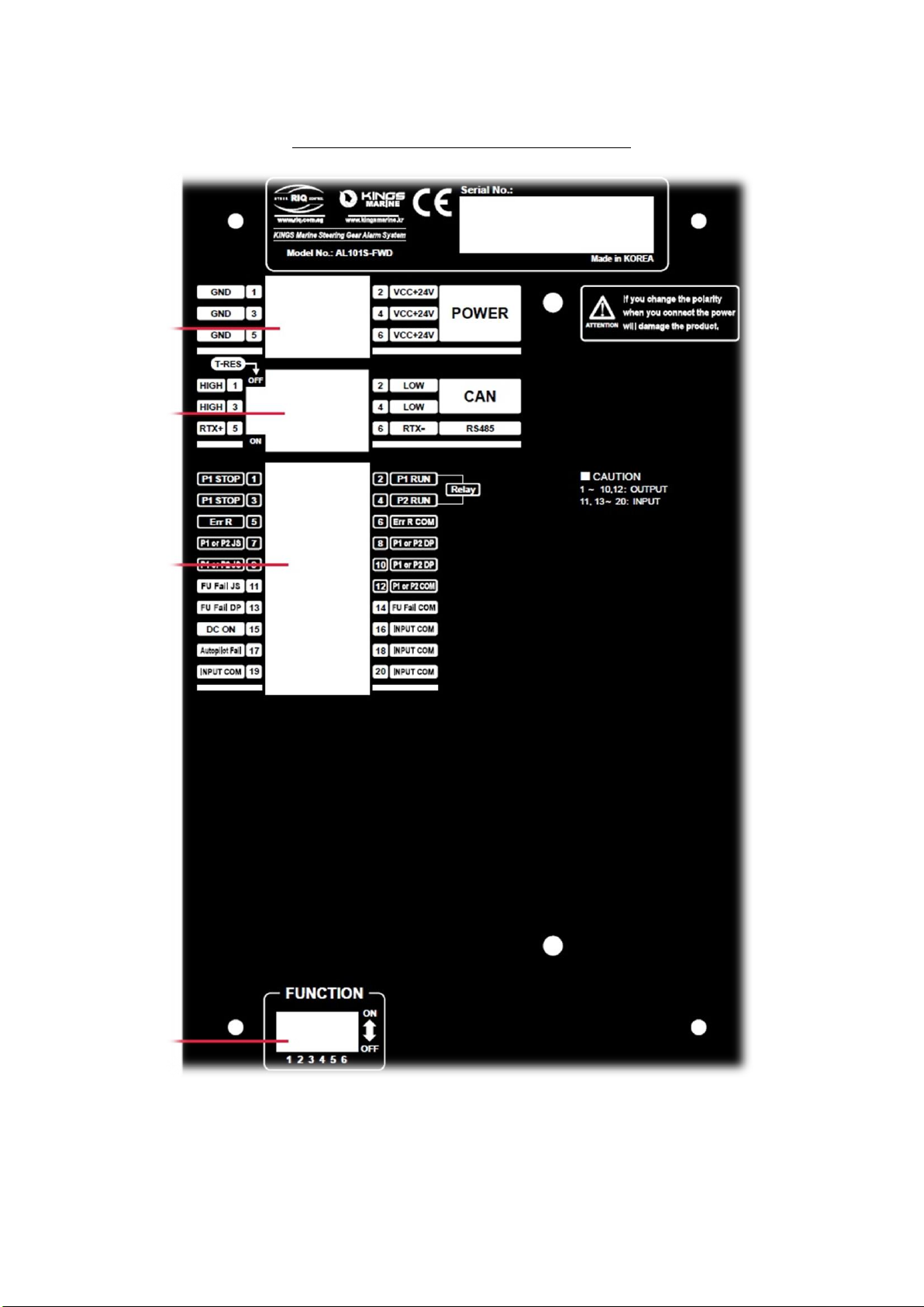
Chapter 3 –Input & Output signal terminal of AL101S ECR / FWD / AFT
Chapter 4 –Test flow chart of AL101S

2
Chapter 0
Factory Default
1. ECR
1.1 Dip Switch
1.2 Resistor Termination ON/OFF switch: OFF
Switch
ON
OFF
Default
1
Operation Mode
Test Mode
ON
2
No DC blinking
DC blinking Available
ON
3
Full Relay output Mode
Half relay output Mode
ON
4
-
-
-
5
-
-
-
6
Operation Mode
Download Mode
ON

3
2. FWD / AFT
1.1 Dip Switch
1.2 Resistor Termination ON/OFF switch: OFF
CAUTION!
ECR / FWD / AFT Relay output mode(Full / Half) run independently.
Switch
ON
OFF
Default
1
Operation Mode
Test Mode
ON
2
No DC blinking
DC blinking Available
ON
3
Full Relay output Mode
Half relay output Mode
ON
4
-
-
-
5
-
-
-
6
Operation Mode
Download Mode
ON

4
AL101S Steering GearAlarm System
Chapter 1
ECR / FWD / AFT
Operation

5
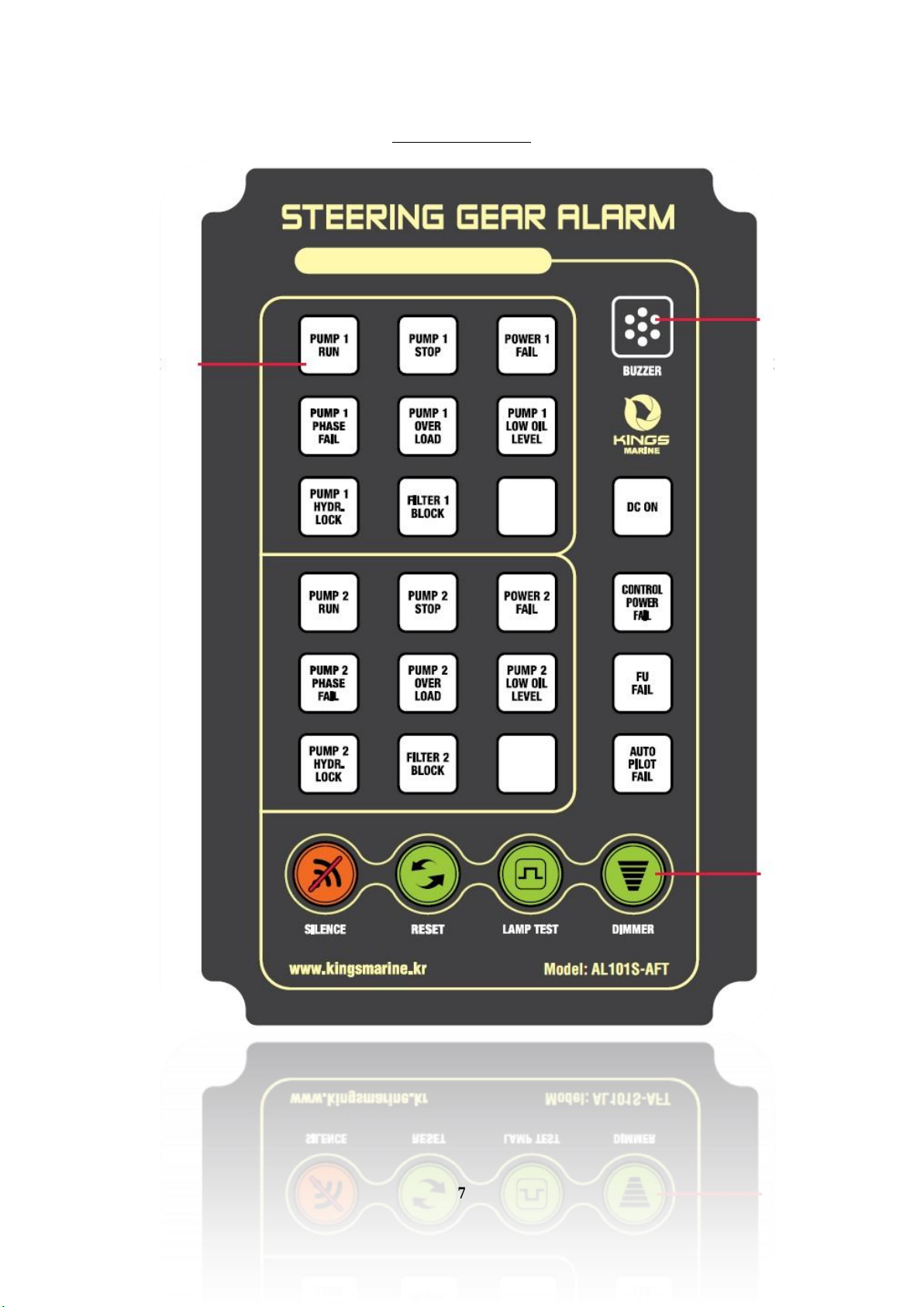
AL101S-ECR
AL101S-FWD
AL101S-AFT

6
AL101S-FWD
7
AL101S-AFT

8
1) SILENCE Key
This key able to maintain to each lamp’s activation or deactivation
After buzzer has activation, this key able to stop to buzzer sound
CAUTION!
If setting Dip Switch “3”setting done ON, relay output will be working full mode.
Meanwhile if setting Dip switch “3”OFF relay output will be working half mode
2) RESET Key
This key able to re-boot to all lamp’s activation and deactivation.
Press this key then press SILENCE Key again to maintain to each
lamp’s activation and deactivation. Or check buzzer sound activation

9
3) LAMP TEST Key
This key able to all LAMP ON even each lamp has activation or deactivation
This key check to LAMP itself working.
If on pressing this key both of activation and deactivation lamp ON at once.
Then if release this key the deactivation lamp will be OFF
4) DIMMER Key
This key able to adjust to LAMP brightness
Brightness has total 5 steps.

10
Description of AL101S-ECR/FWD/AFT LAMP
1) FU FAIL LAMP
Input signal “1”second later LAMP activate
2) PUMP HYDR. LOCK LAMP
Input signal “1”second later LAMP activate
3) PHASE FAIL LAMP
Input signal “2”second later LAMP activate
4) PUMP LOW OIL LEVEL LAMP
Input signal “3”second later LAMP activate
5) DC ON LAMP
Depend on input signal LAMP will be activate to “RED”or “GREEN”
(Please see the chapter 3 Input & output signal terminal)
CAUTION!
Except above FU FAIL / PUMP HYDR. LOCK / PHASE FAIL /
PUMP LOW OIL LEVEL these “4”kind LAMP, the other all
LAMP will be activate once it input signal activate.

11
AL101S Steering GearAlarm System
Chapter 2
ECR / FWD / AFT
Case size
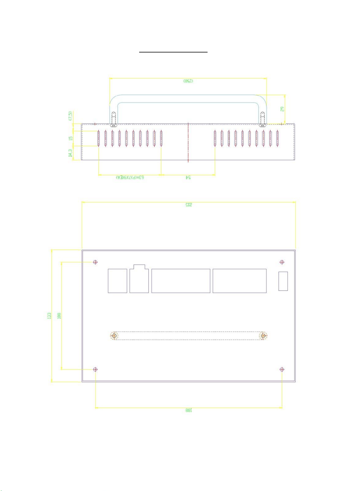
12
Cut hole dimension
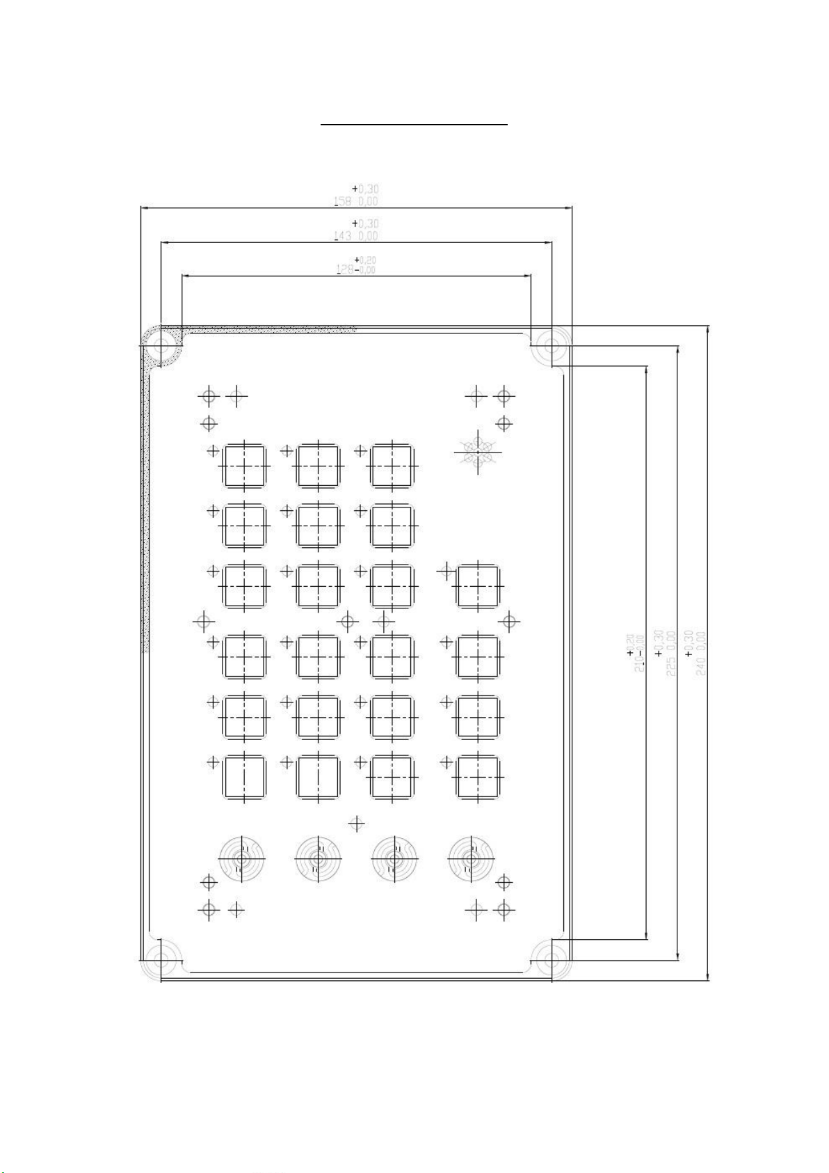
13
Fontal case dimension

14
AL101S Steering GearAlarm System
Chapter 3
ECR / FWD / AFT
Input & output signal terminal
15
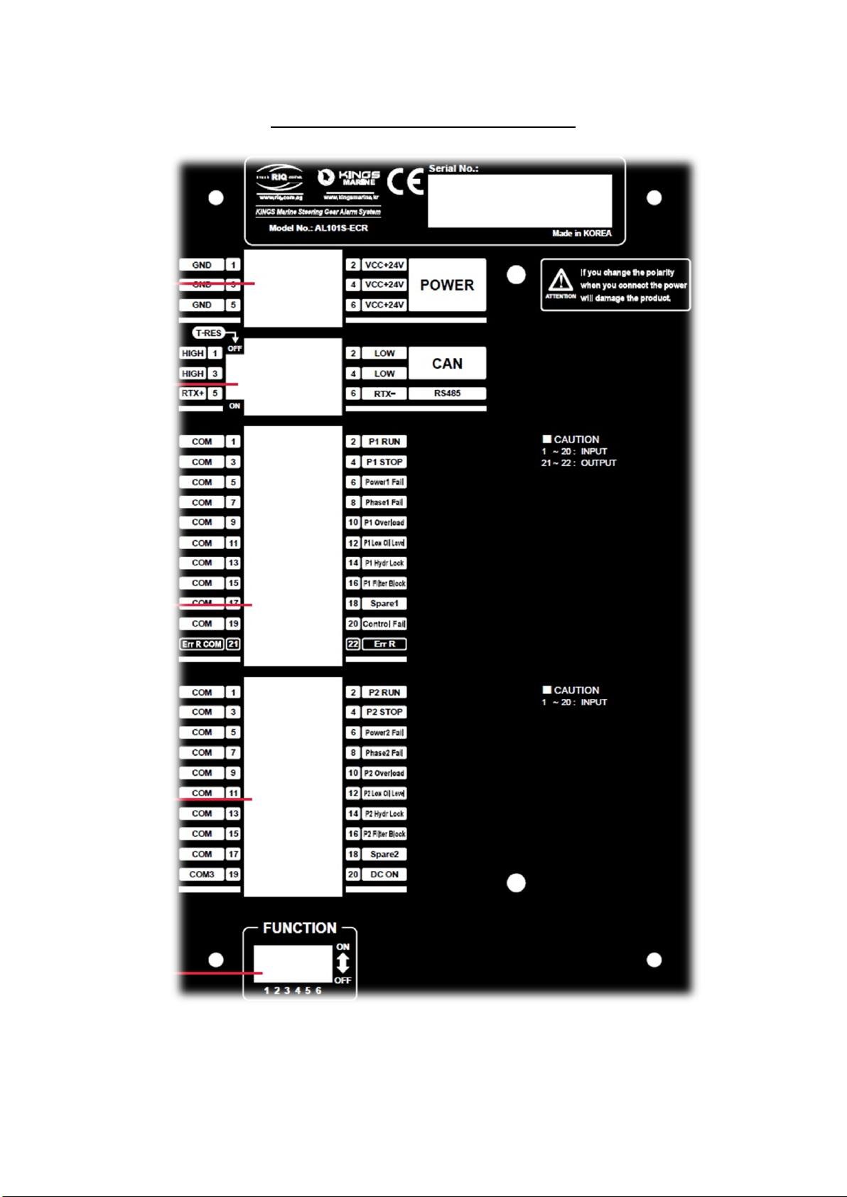
ECR input & output signal terminal
16
FWD input & output signal terminal

17
AFT input & output signal terminal

18
AL101S Steering GearAlarm System
Chapter 4
Test flow

19
4.1 Purpose
: This alarm testing procedure is to check and confirm that the alarm system is
working and meet the design requirement.
4.2 Testing Procedure
4.2.1 Connect the FWD, AFT & ECR panel as single line drawing.
4.2.2 Connect ECR panel to external alarm signals. The alarm signal can be turned off
And on by a toggle switch. The signal is +24V DC. Put the switches in off position
for all the alarm signals before testing.
4.3 Lamp test: Press the lamp test button, all the lamps on the panel should be on.
4.4 Dimmer test: When the lamp test button is pressed, press the dimmer button and the
bright level will be change accordingly.
4.5 Individual alarms and indications test
DC ON
Step 1: Provide +24V DC at the FWD alarm panel input terminal+.
Step 2: DC ON indicator Green light is on all the panels.
Step 3: No alarm activated.
Step 4: Remove the input signal at +
Step 5: The indicator light color changes to Red and alarm activated.
Step 6: check output signal to other equipment at ECR panel when alarm activated
AUTOPILOT FAIL
Step 1: Close AUTOPILOT FAIL contact at the FWD panel input.
Step 2: Autopilot fail indicator Red light is blinking for all the panels.
Step 3: Buzzer sound.
Step 4: Press the Silence button, the autopilot fail indicator light is steady in Red and
Buzzer is off.
Step 5: Press the alarm reset button, the buzzer sound again and indicator is blinking
again
Step 6: Repeat Step 4.
Step 7: Cut off theAUTOPILOT FAIL contact, the autopilot fail indicator is still on
Step 8: Press alarm reset button again, theAutopilot alarm indicator light off.
Step 9: Check out signal to other equipment at ECR panel when alarm activated.
FU FAIL
Step 1: Close FU FAIL contact at the FWD panel input
Step 2: FU FAIL indicator light is blinking for all the panels.
Step 3: Buzzer sound.
Step 4: Press the silence button, the FU FAIL indicator light is steady and buzzer is off.
Step 5: Press the alarm reset button, the buzzer sound again and indication is blinking
Step 6: Repeat Step 4 .
Step 7: Cut off the FU FAIL contact, the autopilot fail indicator is still on.
Step 8: Press alarm reset button again, the alarm indicator light off
Step 9: Check out signal to other equipment at ECR panel when alarm activated

20
Step 1: Close PUMP 1 RUN switch
Step 2: PUMP 1 RUN indicator light ON
Step 3: Buzzer not on.
Step 4: Open the PUMP 1 RUN switch
Step 5: Indicator light off
Step 1: Close PUMP 1 STOP switch
Step 2: PUMP 1 STOP indicator light on
Step 3: Buzzer not on.
Step 4: Open the PUMP 1 STOP switch
Step 5: Indicator light off
PUMP 2 RUN & STOP
-To repeat PUMP 1 RUN & STOP test.
POWER 1 FAIL
Step 1: Provide + 24V DC to the ECR input terminal at P4A
Step 2: POWER 1 FAIL indicator light is blinking for all the panels.
Step 3: Buzzer sound.
Step 4: Press the silence button, the POWER 1 FAIL indicator light is steady and buzzer is off
Step 5: Press the alarm reset button, the buzzer sound again and indicator is blinking again
Step 6: Repeat Step 4.
Step 7: Stop supply +24V DC to the terminal input, the power 1 fail indicator is still on.
Step 8: Press alarm reset button again, the alarm indicator light off.
Step 9: Check out signal to other equipment at ECR panel when alarm activated.
*All the other alarm testing has the same testing procedure as POWER 1 FAIL test procedure.
TIME DELAY TEST
LOW OIL LEVEL: 3 second
HYDRAULC LOCK: 1 second
PHASE FAIL: 2 second
FU FAIL: 1 second
*The testing steps are same as POWER 1 FAIL.
Step 1: Provide alarm input signal to the respect alarm input terminal.
Step 2: Count the time between signal input and alarm activate.
Step 3: Compare the time between the setting an count.
Step 4: The time delay setting and count should follow the setting time
PUMP 1 RUN
PUMP 1 STOP
Table of contents
Other Sewhacnm Security System manuals


