SEWOO SLK-T213EB Series User manual

T21EB Series ENG Rev. I 01/2021
Aroot Co., Ltd.
28-6, Gajangsaneopdong-ro, Osan-si, Gyeonggi- do, 18103, Republic of Korea
TEL : +82-31-8077-5000 / FAX : +82-31-624-5310
http://www.miniprinter.com

All speci cations are subject to change without notice
MODEL : SLK-T21EB SERIES
Receipt Printer User’s Manual

This device co mplies with part 15 of the FCC Rules.
Operation is subject to the following two conditions.
1) This device may not cause harmful interference, and
2) This device must accept any interference received,
including interference that may cause undesired operation.
Vic Barczyk
19700 S Vermont Ave Ste 200 Torrance, CA 90502 | USA
sales@miniprinter.com
Henning Mahlstedt
26188 Edewecht, Holljestr.9 | Germany
europe@miniprinter.com
Victor Almazan
Paseo de la Reforma No. 265 Piso 2.Ocina SBC. Col.
Cuauhtémoc, C.P. 06500 Ciudad de Mexico | Mexico
sales@miniprinter.com
Yan xiao rui
Room 902, No. 7, Lane 118, Xiaojishan Road, Sheshan Town,
Songjiang District, Shanghai | China
sales@miniprinter.com

Disposal of Old Electrical&Electronic Equipment(Applicable in the European Union and other
European countries with separate collection systems)
This symbol on the product or on its packaging indicates that this product shall not be treated as
household waste. Instead it shall be handed over to the applicable collection point for the recycling of
electrical and electronics equipment. For more detailed information about recycling of this product,
please contact your local city oce, your household waste disposal service or the shop where you
purchased the product.

2
1. Parts Identications 3
2. Setting up the printer 4
2.1 Unpacking 4
2.2 Connecting the cables 5
2.3 Loading the roll paper 8
2.4 Adjustment of paper width 11
3. Control panel and other functions 12
3.1 Control panel 12
3.2 Error Indicating 12
4. Self Test 13
5. ASCII Print 14
6. ECO Mode 14
6-1. Font 14
6-2. Paper Reduce
15
6-3. Density
15
7. Printer Setting 16
7-1. Baudrate 16
7-2. Cutter
16
7-3. Error Beep
16
7-4. Melody
17
8. Hexadecimal Dump 18
9. Printer Cleaning 19
10. Specications 20
11. Command List 22
12. Utilities 24
13. S/W 25
Table of Contents

3
1. Parts Identications
CONTROL PANEL
Features LED indicators
to indicate printer status
and switches to operate
the printer.
Features LED indicators to
indicate printer status and
switches to operate the
printer.
COVER OPEN LEVER
Used to turn on/o
power to the printer.
POWER SWITCH
Open this cover to
load or replace paper.
PRINTER COVER

4
2. Setting Up the Printer
2-1. Unpacking
Your printer box should include these items.
If any items are damaged or missing, please contact your dealer for assistance.
The Printer CD Roll Paper
Adaptor(option) Interface Cable(optional)
5
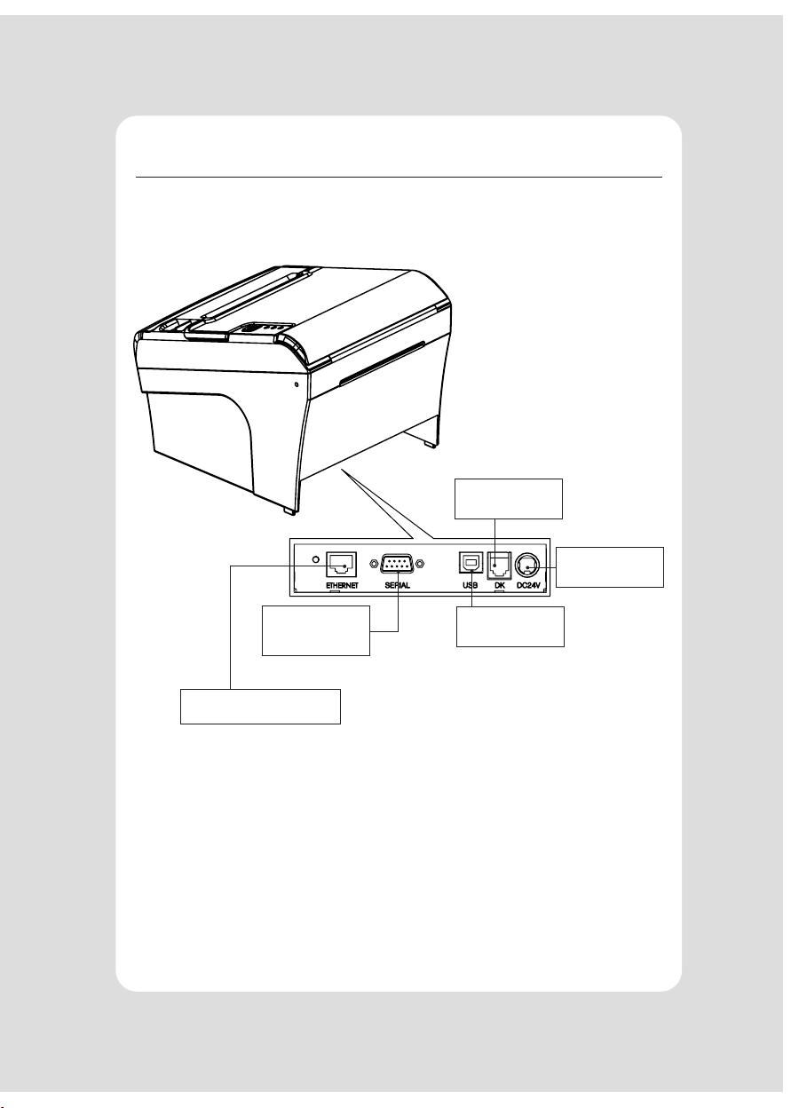
2-2. Connecting the Cables
You can connect up the cables required for printing to the printer.
They all connect to the connector panel on the back of the printer, which is shown
below :
INTERFACE CONNECTOR
(ETHERNET)
INTERFACE CON-
NECTOR (SERIAL)
INTERFACE
CONNECTOR(USB)
POWER CONNEC-
TOR
CASH DRAWER
CONNECTOR
Before connecting any of the cables, make sure that both the printer and the
computer are turned o.

6
2-2-1. Interface Connector
4 3
21
9 Pin Serial USB “B” Type
Status LED
123453678
Link END
Ethernet
9Pin Serial Interface
PIN SIGNAL I/O Description
2RXD Input Printer receive data line
3TXD Output Printer transmit data line
4, 7 DTR Output Data Terminal Ready
5GND -System Ground
6DSR Input Data Set Ready
1,8,9 NC - -
USB Interface
PIN SIGNAL I/O Description
1+5V -+5V
2DATA- -Printer transmit data line
3DATA+ -Printer transmit data line
4GND -System Ground
7
USB Interface
PIN SIGNAL I/O
1Data Out + Output Data +
2Data Out - Output Data -
3Data IN + Input Data +
4N.C -
5N.C -
6Data IN - Input Data -
7N.C -
8N.C -
This equipment is indoor use and all the communication wirings are limited to
inside of the building.
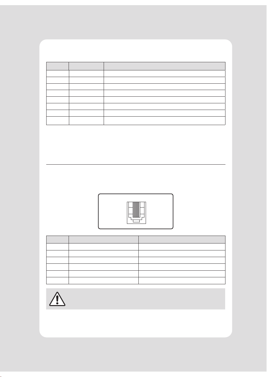
2-2-2. Cash Drawer Connector
The printer can operate two cash drawers with a 6 pin RJ-11 modular connector.
The driver is capable of supplying a maximum current of 1.0A/24VDC for 510ms or
less when not printing.
61
PIN SIGNAL Description
1Signal GND -
2Drawer kick-out drive signal 1 Output
3Drawer open/close signal Input
4+24V -
5Drawer kick-out drive signal 2 Output
6Signal GND -
CAUTION
Please make sure you hear the closing sound of the upper cover.

8
2-3. Loading the Roll Paper
NOTE
Be sure to use paper rolls that meet the specications. Do not use paper rolls
that have the paper glued to the core because the printer cannot detect the
paper end correctly.
Turn o power switch.
1 Make sure that the printer is not receiving data; Otherwise, data may be lost.
2 Open the paper roll cover by pushing down the cover open button.
3 Remove the used paper roll core if there is one inside.
4 Insert new paper roll as shown.

9
5 Be sure to note the correct direction that the paper comes o the roll.
O X
6 Pull out a small amount of paper, as shown. Then, close the cover.
7 Tear o the paper as shown.
10
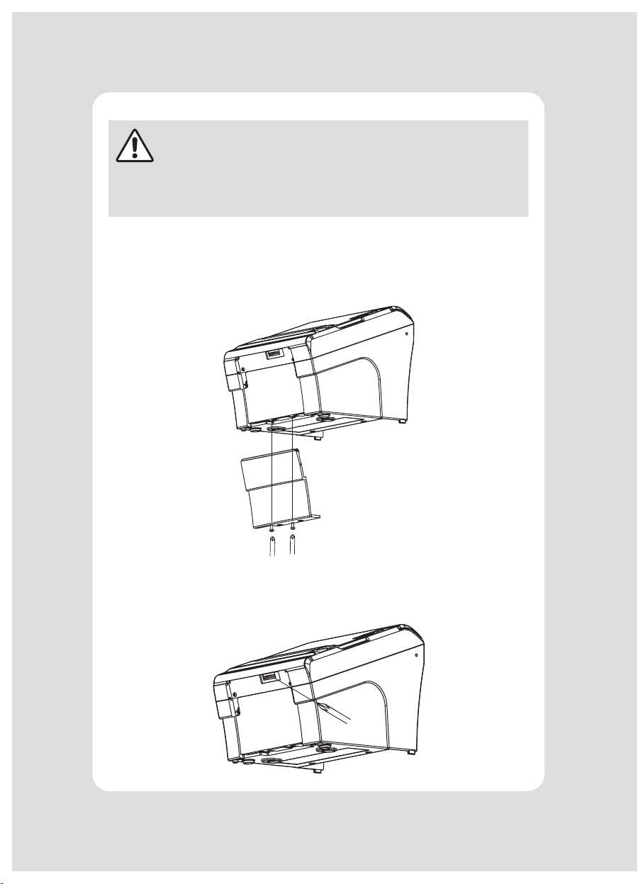
CAUTION
When the paper is jammed with cutter, the top cover might be stuck.
In this case, repeat power on and o several times.
If the top cover is still stuck, please follow the steps to release the
papers from jamming.
1 Make sure the printer is turned o.
2 Remove the screw from the DIP switch cover. Then, take o the DIP switch cover
as shown in the illustration below.
3 Turn screw with drivers to a direction until paper is released from the cutter.
11
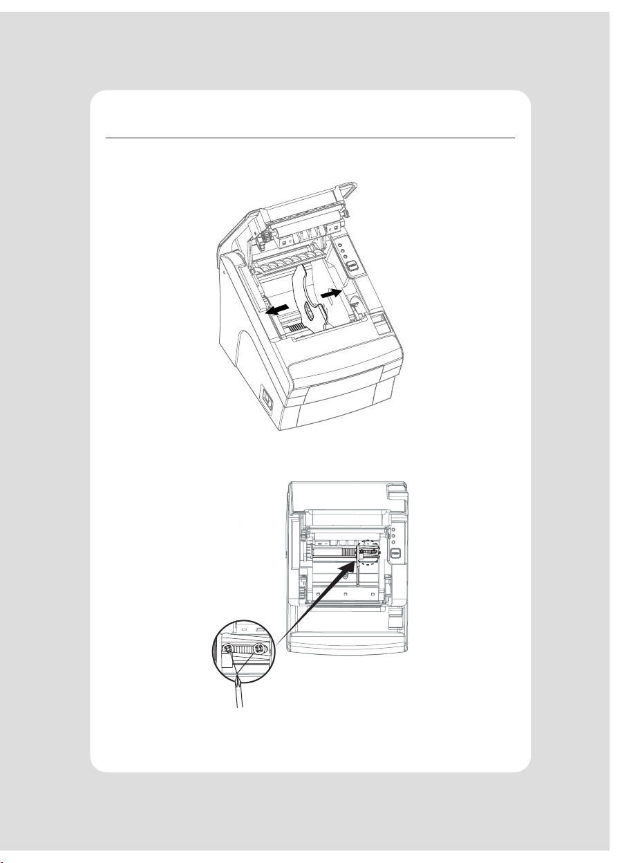
2-4. Adjustment of paper width
1 Please adjust the Paper Guide to t to the paper width as the direction of arrow.
2 Tight the screw after adjusting the Paper Guide.
3 Pull the edge of paper once the paper roll is installed correctly and close the
Paper Cover.

12
3. Control panel and other functions
3-1. Control panel
You can control the basic paper feeding operations of the printer with the button
on the control panel. The indicator lights help you to monitor the printer’s status.
Control Panel
Button
The button can be disabled by the ESC c 5 command.
Press the FEED button once to advance paper one line. You can also hold down
the FEED button to feed paper continuously.
3-2. Error indicators
STATUS
PAPER ERROR POWER
REMARKS
RED RED GREEN
Power o
OFF OFF OFF
Normal power is not supplied to the printer
Power on
OFF OFF ON
Normal power is supplied to the printer
On line
OFF OFF ON
Normal error-free mode
Cover open
OFF ON ON
Close cover
Paper end
OFF ON ON
Insert new paper roll
Paper
near end
ON OFF ON
Paper is low

13
4. Self Test
The self-test result indicated whether the printer is operating properly.
Also with this, user can check following options or status of the printer.
Control circuit
Printer mechanism
Printing quality
ROM version
Interface setting
This test is independent of any other equipment or software.
Running the self test
1 Make sure the printer is turned o and the printer cover is closed properly
before performing the self test.
2 Turn the printer on holding the FEED button, then the self-test will start.
The self-test prints the printer setting value and then prints the following,
and pauses. (Error LED On)
SELECT MODE BY BUTTON
1. ASCII PRINT
2. ECO MODE
3. PRINTER SETTING
4. HEXADUMP MODE
3 Press the FEED button consecutively (1~4)
1. ASCII PRINT
(press the FEED button once) Printing test page constructed with ACII code.
2. ECO MODE
(press the FEED button twice)
Set the ECO mode for saving paper and power.
(Default font type, Reduce paper margin, Density)
3. PRINTER SETTING
(press the FEED button triple time)
Set the printer option.
(Serial baudrate, Cutting mode, Error beep, Melody)
4. HEXADUMP MODE
(press the FEED button quad time)
Printing the HEX value received from the interface
※ Wait for 5~6 seconds if you want to exit. Printer performs a cutting when exiting
this mode
4 The printer is ready to receive data after nishing setting.

1414
5. ASCII Print
6. ECO Mode
ASCII PRINT is printing a test page constructed ASCII code. You can able to check the
printer works properly with this
The ASCII PRINT test automatically ends and cuts the paper after printing the following:
*** Completed ***
The printer is ready to receive data as soon as it completes the ASCII PRINT.
After entering the ECO MODE, the list which can select the ECO option will be printed.
Similar like Self Test, you can press the FEED button to select a ECO option.
Once the input performs properly, the printer shows a result and store.
ECO MODE
1. FONT SETTING
2. LINE SPACE SETTING
3. LINE FEED SETTING
4. BARCODE[1D] HEIGHT
5. DENSITY SETTING
6-1. Font
FONT SETTING menu can be change the Font mapping(FONT A / FONT B).
If you did not want other side font, you can disable that.
-FONT A : 12x24
-FONT B : 9x17
FONT SETTING
1. FONT A -> A / FONT B -> B
2. FONT A -> B / FONT B -> B
3. FONT A -> A / FONT B -> A
4. FONT A -> B / FONT B -> A

15
6-2. Paper Reduce
Reduce menu (Line space, Line feed, barcode[1D] height) was developed for paper
saving.
-Line space
“Line space” means the amount of feed when you intentionally generate newlines.
-Line feed
“Line feed” means the amount of feed when there is an automatic line break.
-Barcode Height
“Barcode Height” means the height of the barcode when creating a one-dimen-
sional barcode.
LINE SPACE SETTING
01 NORMAL
02 REDUCE 50%
03 REDUCE 75%
04 REDUCE 90%
LINE FEED SETTING
01 NORMAL
02 REDUCE 50%
03 REDUCE 75%
04 REDUCE 90%
1D BARCODE HEIGHT SETTING
01 NORMAL
02 REDUCE 50%
03 REDUCE 75%
04 REDUCE 90%
6-3. Density
Adjust the print density to save the power consumed by the printer.
SELECT DENSITY
01 NORMAL
02 LOW
03 DARK

16
7. Printer Setting
Change the printer settings. The options below can also be changed via the
Memory Saver.
PRINTER SETTING
01 SELECT BAUDRATE
02 SELECT CUTTING MODE
03 SELECT ERROR BEEP OPTION
04 SELECT MELODY OPTION
7-1. Baudrate
After entering the BAUDRATE MODE, the list which can select the BPS will be printed.
Similar like Self Test, you can press the FEED button to select a BAUDRATE. Once the
input performs properly, the printer shows a result and store. The printer is ready to
receive data as soon as it completes the SELECT BAUDRATEMODE.
SELECT BAUDRATE
01 4800bps
02 9600bps
03 19200bps
04 38400bps
05 57600bps
06
115200bps
7-2. Cutter
Set cutter mode.
SELECT CUTTING MODE
01 PARTIAL CUT
02 FULL CUT
7-3. Error Beep
If the cover is open or there is no paper, the error beep function is activated.
This option allows you to enable / disable the error beep.
SELECT ERROR BEEP OPTION
01 BEEP ON
02 BEEP OFF

17
7-4. Melody
To DK Port (Cash), Melody box or external buzzer can be connected.
You can activate it from the Melody Setting menu, and the melody will operate after
the cutting operation.
-Melody Box : Melody is xed and volume can be adjusted.
-External Buzzer : 3 types of melody are output according to the Melody Type
setting and volume control is not included
SELECT MELODY OPTION
01 MELODY SETTING
02 SELECT MELODY TYPE
MELODY SETTING
01 MELODY ON AFTER CUTTING
02 MELODY OFF
SELECT MELODY TYPE
01 MELODY-Ⅰ
02 MELODY-Ⅱ
03 MELODY-Ⅲ
Table of contents
Other SEWOO Printer manuals

SEWOO
SEWOO SLK-TL100 User manual

SEWOO
SEWOO SLK-TL21 Series User manual

SEWOO
SEWOO LK-P300 User manual

SEWOO
SEWOO LK-P12 Release note

SEWOO
SEWOO SLK-TS400 User manual

SEWOO
SEWOO LK-P41B User manual

SEWOO
SEWOO SLK-TE25 User manual

SEWOO
SEWOO TL32 Series User manual

SEWOO
SEWOO LK-P12W User manual

SEWOO
SEWOO LK-P11B User manual

SEWOO
SEWOO LK-D10 User manual

SEWOO
SEWOO SLK-TL122 User manual

SEWOO
SEWOO LK-P31 User manual

SEWOO
SEWOO LK-P31 User manual

SEWOO
SEWOO LK-P30B User manual

SEWOO
SEWOO SLK-T21EB Series User manual

SEWOO
SEWOO WTP-150 User manual

SEWOO
SEWOO LK-P21 User manual

SEWOO
SEWOO SLK-D10 User manual

SEWOO
SEWOO LK-P20B User manual


