manuals.online logo
Brands
  1. Home
  2. •
  3. Brands
  4. •
  5. SFA
  6. •
  7. Water Pump
  8. •
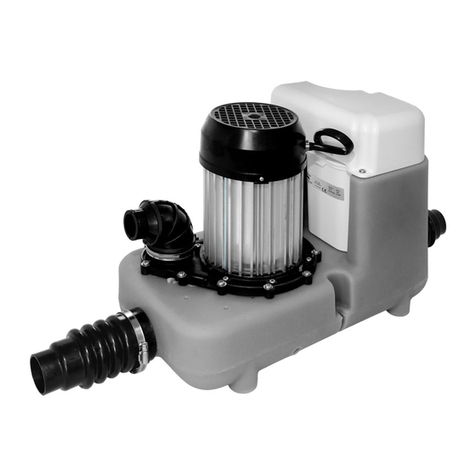
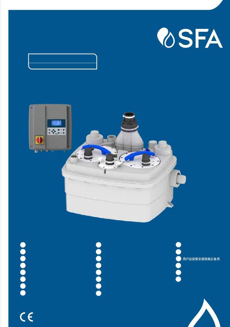
  9. SFA SANICUBIC 2 User manual

SFA SANICUBIC 2 User manual

APPROVED
PERMIT #:
Community Development Department
Al Christensen, CBO
Building/Fire Safety Plans Examiner
10/10/20172:39:49 PM
TUM-17-1134
SEE DETAIL OF
PUMP
For
Customer
Service,
Returns
or
Technical
Questions,
please
ca
ll
Saniflo's technical support toll-free
at
800-571-8191
(USA)
or
800-363-587
4
(CON).
Pour
le
service
cli
e
nt
, les re
tours
ou
toute
question
technique,
merci
d'appeler le
service
technique
de
Saniflo
au
numero
suivant
:
800-571-8191
(USA)
ou
800-363
-
587
4 (
CON).
Th
e
us
er
should
re
tain
these
instructions
for
future
reference
• A
lire
attentivement
et
a
conserver
a
titre
d'information
This product must
be
installed
in
strict accordance with local plumbing codes. ·
Product should
be
installed by a licensed plumber.
Le produit doit etre installe dans
le
respect des reglements sanitaires locaux.
Le
produit do1t etre installe par un plombier qualifie.
2266
15
@@
------
-
-----
---
~~~--
--
-
-
--
------------------------------------
----~
'
i
I
40
/
60
L__
___
-
L.
~'
.,
.
•..
-..
..
...
.
..
. ..
·····
········
..
·
····
·
----····
··
--·-------·-····
·
·····--
- -
f
~
;
i
-~:
:
~~
i
.-
10
45
50
32/50
~
r.D
* ,.
..
....
n,
55
60 65
70
75
30
-
~
11
I
I
tiij
3-3i8"
r.:c=
ii 5
/8
"
I
I
85
90
i
?1
;- 1 •..,
F:
o-:c
•;,:h 1 1nctor
(g
allons
/min)
Debit (gallons/min ) a
ve
c 1 moteur
i
P1
+P2
r iu
vv'
R2,te with 2 moto
rs
(gallons/min ) Debit (gallons/min ) avec 2 moteurs
L
.-
---
--
---
--
-·--·······-------
--
----
--
--
-·--
---
----------------
-
* cf.
[J]
10116
~
x1
{~~
\~-~~
~__;>
6
feet
·
---
-------
-
----·····-
..
··
·······
·
··-·
··
--
-
---
-----~
£11
maxi65
Ft
~
fl
A maxi98
Ft_
OK
[
~
.,
.
'=
max1131Ft_
fl
i
to<
maxi164Ft_
~
-
F,-..c_,
~~
-===
~
==---±.o
''
==
·
"'-o__
maxi
197
Ft_
rr-
- - ,!•, -
ire-:::_:~
~-
_:_
_
_
_
max
i
229
Ft_
1
11
..
.
,~
.
I
~::ii_::_
m•~:
~::~
,"
~--,--
~~
maxi
360 Ft
I
-·-···--··
-··
-·
····---··--··
··-·----
·
·-----.1
'-··------·---
r
-/
;
=rJJ
::
;~
~=i:
/~
I ,
;>
I .,
._"
I
"'
:..-
I
i
i
[
__
'·
.
-"-'"'-'"'--"
C.:.....:.:-"--'-=-:.:=..:.:_:;___ ·_··j
__
,__
______
_
__J
1Jit;,•"''l\~1f
-
-
---
--
-
-
·----·
·--
.
;1,:1;
:
.:
1
iiii
SANICUBIC® 2
R300
LC
!
Societe
Frarn;aise
d'
Assainissement
220-240
v -
GO
Hz
L__
___
EN
1295Q-1
____________
__
2_ x_1_ H_P_-
-:1:-
The
!l
u
mber
s refer to
the
explan
ato
ry diagr
ams
.
f
·~.
.
~-~
;-:.~
~~:~.
·:~,.·:'
'
..
~:·
- :-:-
-·-
-
---
'
~~
~
~~~
I~~
~
-
;~~
:~
a lifting sta
ti
on desig-
1 ned
to
evacuate effluent f
ro
m small private .
: or commerci
al
units. 1
I
Pl
ease comply with
al
l the installat
io
n a
nd
I
I
maintenance specificauons set our in
rh
ese'
1nstr
uct1ons,
and especially the information
marked with
th
e
fo
llowing signs:
" ii\
,,
Fa
ilure to comply with
th
is
~
info
rm
ation cou
ld
enta
il
safety
hazards for personnel,
"
··
?\
,,
Informa
ti
on warning of the pre-
!
····
···
sence of an electrical haza
rd
,
!"'
/.~
,
,,
Instruc
ti
ons o
nl
y for qualified
i · professional specia
li
st
s,
I"'J·i1iFn-i1'F;
,,
Fa
il
ure to comply with this
i informa
ti
on could affect
th
e no
rm
al
I opera
ti
on of the equipment.
iPlease contact our Customer servi
ce
for
further
in
formatio
n.
SANICU
BIC
OPE
RATING
PRINCIPLE
SANI
CU
BI
C®
2 contains 2 separate pumps.
Each of t
he
pumps
is
fitted with a hig
h-
per-
fo
rm
ance macer
ati
ng system.
T
he
2 pumps operate alternatel
y.
In the
event of in
fl
ow overload, both motors run
at
th
e same time (or
if
one of the pumps
I
is fault
y,
the other one takes over).
The SANICUBIC"'2 tank
is
fitted with 2 dip
I
tubes; one
tu
be co
nt
ro
ls motor
operation, and the other one controls the
alarm syste
m.
- L
on
g
pickup
tube
(normal operation):
as soon as
th
e waste water level
in
th
e
tank reaches the triggering point in the
long tube,
th
e pumping system sta
rt
s up.
-
Short
pi
ckup
t
ube
(inflow overload
operation):
if
the waste water level
in
the
tank reaches the upper point, a
co
nt
act
is
cl
osed, and
th
e auxiliary pumping system
I is triggere
d.
The contact also sets o
ff
an
visual alarm.
Th
e general alarm LED on
I
th
e SANICU
BI
C®
2 control panel switches
t
___
tel
~~
-
<L
_
i
Vo
l
taqe
220
-
240V
I
Frequency
60
Hz
IV
ol
u
me
12
Ga
ll
ons
Maxi
mumo
owe
ri
nou
t 2x1
HP
Maxim
um
c
urr
en
t
inout
13
A
El
ec
t
rica
lcl
ass
ifi
ca
t
ion
I
Ave
water
temo
fo
r
ootimum
nerf
ormance
1
04
F
Maxim
umt
em
oer
atu
re
(inte
r
mit
t
ent)
1
60
F'
Protec
t
ion
i
ndex
I
P67
1
Ne
t
weight
(inc
ludi
ng
accessories)
66
L
bs
l
.
·
.
~~t
..
w~e'.
_~~~
i
~
-
~Y_c!::!r
_
o":'_dishw
_
ashers
or washing machines
Iu PERFORMA ICE CURVE
I
Example: Pump
P1
is
operating normally.
, It discharges 38 gpm at a pumping heig
ht
I
! of 16
Ft.
If pump
P1
shows any signs of
wea
kn
ess or if the waste water inflow
is
1 too great, pump
P2
starts up. The output
Iis then increased
to
about 64 gpm, until
Ithe situation returns
to
norma
l.
fA RATIO
OF
HEIGHT/LENGTH I
'--
____
F
__
O
-'-'
R
-=
D
-=
iS
=-
C:c...:H
_c:_
A_c:_R.::_G,=E
"---
-·------'
[]
INSTALLAT
ION
The SANI
CU
BI
C®2
must be
in
stalled
in
compliance with local plumbing
codes. The equipme
nt
must be
Icommissioned and maintained by a
qual
ifi
ed professional special
is
t.
ITri
REG
ULATIONS
1-
Attentio
n:
the space in which the
SANICUBIC®2 is to be installed must
be large enough to leave at least 24"
of worki
ng
room around and above
th
e
unit to facil
it
ate such maintenance work
as may be required. There must be suf-
ficie
nt
l
ig
htin
g,
and
it
mu
st be
sufficie
nt
ly well ventilat
ed
a
nd
protect
ed
from
fr
eezing. I
2- Isolat
ing
va
lves
{not
suppli
ed)
must
I
be fi
tted
on
waste
i
nlets
(especially 1
the
4"
inlets
) and
on
the
disc
harge I
to
ensure
that any service/mai
nte
-
na
nc
e may
be
carried o
ut
safely). !
3- The discharge pipe must be
fi
tted so as i
to avoid all back flow from the dra
in
age !
system (see the examples
in
drawing !
l!'l). Back
fl
ow can be avoided by !
installing an anti-back flow riser ·
reaching a high point above the i
max
im
um back
fl
ow leve
l.
Comm
ent
:
In
the absence of local
information
to
the
contrary,
the
!
maximum back
flo
w level corr
es
ponds j
to street level (roadway, pavemen
ts,
t
etc.
).
Conti
nu
e
th
e
di
s
ch
arge pipewo
rk
1
1_
aft
er the anti-backflow
ri
se
r, using a
larger diameter pipe. i
4- If the Sanicubic is
in
stal
le
d
in
a space
1·
su
ch as a pit for example, we wo
ul
d
recommend the fitting of a
bi
lge pump I
in
case of floodi
ng
.
5- The lifti
ng
sta
ti
on
mu
st be
ve
nt
ed with I
an o
utl
et at
ro
of leve
l.
1_,
1
6-
The
li
fti
ng station
mu
st be
fi
xed
to
the
fl
oor (see
t:J:l).
!
rn
coNNECTING
THE
mscHARGE
PIPE
I
Remove the end cover or covers f
ro
m the i
back of the u
ni
t (cf.
Dl1
w
).
Ii
As each pump is
fi
tted
wi
th
a ma
ce
rator
syste
m,
an
1-1/2" discharge pipe can be
us
ed
. I
The
di
scha
rg
e be
nd
is at
th
e centre of the I
unit, at the back (cf.
CTI).
U
se
a sta
nd
a
rd
I
1-1
/2
" coup
li
ng (not provided) to
co
nn
ect 1
it
to the
ri
ser pipe a
nd
fi
x it
in
pl
ace
wi
th !
metal clamp
s.
i
Each pump
in
the SANICUBI
C®
2
un
it is j
fitted with check val
ve
s. i
--
NNECTING SANITARY
I EQUIPMENT TO THE LOWER
INLETS
I
I
I\
If
you
wa
nt
to
install a sh
owe
r
or
I
L_L'..
a bath at the
same
level as
the
SANICUB
IC
®
2,
yo
u must make
sure that the upper parts
of
the plu-
gholes
on
the
sani
tar
y equipme
nt
are at
l
ea
st 10" above the
lower
inlets.
t:1n
CONNECTING
THE
INLETS 1-1/
2"
Lo
we
r i
nlets
(cf.
t:1n
CiJ)
IU
ppe
r
inl
ets
{cf.
t:1n
~
I·Cut o
ff
the end of the
1-1
/2" inlet with a
' saw
· Cut the sleeve 8
to
suit the pipe
diameter: 1-1/4" or 1-1/2"
(c
f. tJn[3])
·
Fi
x the sleeve 8 on the inlet and on t
he
pipe, using the collar
s.
r!l
CONNECTI
NG
THE
4"
INLET
Lo
we
r
inl
e
ts
(
cf
.
rn
[ii)
1-
Remove the plug from the side i
nl
et.
2- Fix the sleeve
[]
in place u
si
ng
the
collar.
l!J.
3- Fully inse
rt
the
4"
tube in the o
th
er end
of
th
e sleeve and
fix
it
in
place u
si
ng
the o
th
er co
ll
ar.
~l
Upper inl
ets
(cf.
rn
~
1- Cut off the upper end of the
4"
inlet
with a saw.
2- Fix the sleeve
ll
in
place u
si
ng the
co
ll
ar
l!J.
13-
Fu
lly inse
rt
th
e
4"
tube
in
the other end
I of the sleeve and fix it
in
pl
ace usi
ng
th
e other collar
l!J
.
------·--
---
------
[J]
CONNECTING THE VENT
1- VENT OF SANICU
BIC®
2
One
of
the
u
pper
1-1/2" inle
ts
must
be
u
sed
fo
r the vent. The
vent
pipe
m
ust
be fi
tt
ed up
to
roof
level.
C
ut
off
the
end
of
the
on
e
of
the
1-1/2" inl
ets
with a s
aw
.
Then f
ix
the slee
ve
8
in
place
u
sing
the
coll
ar G .
Fully i
ns
e
rt
the
1-1/
2"
tub
e in the
other
end
of
the
sl
e
eve
and
fix
it
in
pla
ce
u
si
ng
the
ot
her
coll
ar
[3.
V'h\RN!NG: Note
that
the
ve
nt
sy
ste
m
sh
ould
be
a
two-w
ay
air
vent.
T
he
use
of
me
c
han
ical ven
ts,
air
adm
ittance
va
lv
es
or
simil
ar
devices
are
not
permitted
as
these
are
consi-
dered
one
-way a
ir
vent
sy
ste
ms.
The v
ent
must
be
an
ope
n vent
or
the
un
it
wi
ll
no
t operate.
2- V
EN
TING THE ELECTRI
CAL
PART
Co
nne
ct the
8/11
clear PVC t
ubing
{III)
su
pp
lied to
the
keyboar
d on the
Sa
nicubic.
The
oth
er e
nd
of
th
is
tubing
mu
st
be l
ocate
d between 3 Ft
and 6 Ft a
bov
e t
he
de
vice
to
avoid
wate
r
gett
i
ng
into
the
ele
ct
r
ical
pa
rt
in
the
ev
e
nt
of
flooding.
Import
a
nt:
do
not
pinch
the
tubing.
~------
-
--------
-----
--'
I
a,
DRAINING '
I
.
The SANI
CU
BIC®2
unit is fitted with 2 plugs
(~r:tl)
.
Disconne
ct
the
un
it
from
the
powe
r
sup
ply.
1To
drai
n the
uni
t
1
1-
Unclip the cover.
1 2- Remove one of the 2 plugs.
1
3-
Inse
rt
a
we
t uti
li
ty vacuum cleaner pipe to dra
in
the u
ni
t.
The
· port diameter is 1-1
/2"
.
: 4- When the unit has been drained, put
: the plug and then
th
e cover back
in
place.
!
' -
-·-·-·--
--------
-----
--
i
CT:l
FIXING
TH
E SANICUB
IC
lJNIT TO THE FLOOR
1 The SANI
CU
BI
C®2 unit
is
equipped wi
th
fittings to hold
it
on
th
e
'.
floor and prevent it from turni
ng
or mov
in
g.
'
1
1-
Place the unit on the desired spot.
i 2- Draw the outline of the uni
t.
j3- Position the brackets and fix them
to
the floor as shown on
th
e
1 template diagram
(rn:l
~
).
!
1
4-
Put the unit back
in
pl
ace. I
!5- Fix the unit in place with the screws. I
! .····-···"""
....
______
_______
____
I
l
DJ
ELECTRICAL CONN
EC
TIONS
!1- The electrical
in
stallation work
mus
t be carried out by a
l qualified electrician.
· The electri
ca
l installation must comply with the standards
in
l
force
in
the
country
concerned
!
J 2-
The
power supply must be of the class 1 type. The unit must
, be connected via an earthed connection box. The electric
I
power
circu
it
must be protected
by
a high-sensitivity 30 mA
! differential circuit breaker set at 20
A.
The connection must
I
I be used solely to power the SANICUBI
C®
2.
If
the power lead
1 on the unit is damaged,
it
mus
t be replaced
by
t
he
manufac-
1
lurer
or its after-sales service to avo
id
a
ll
danger.
i
I
...
_
·--------~
J
l
;
1/
General
alarms:
i
Hig
h
leve
l
alarm:
IIf the water level in the unit is abnorm
al
ly h
ig
h: the red L
ED
!
comes
on;
th
e other motor sta
rt
s up 3 seconds later (see the
iillustration showing the control keyboard).
i
i
Temporary
alarm:
!If one of
th
e 2 motors runs for more than 1 minute: the red
Ialarm LED comes on; the other motor starts up 3 seconds later.
!
21
Rese
tt
i
ng
th
e
ge
neral
al
ar
ms:
j
1f
the problem that has triggered
one
of
the alarms refe
rr
ed to
I
above
ceases, the red alarm LED stays on to memorize
th
e
Ifact that the system has met with a problem.
IThe "Reset alarm" key on the k
ey
b
oa
rd switches the red LED
: o
ff
if the problem that triggered the alarm has been dealt with.
I
This
avoids the risk of having a system "abandoned" in fault
Istatus.
i
IUNIT
~
-
LARM
I
I
EXTERNAL WIRED ALARM
REMOTE ALARM MODULE
:The external alarm box of the
ISANICUBIC
""
2 does n
ot
require
ian
in
depe
nd
e
nt
power suppl
y.
I
It
is
powered via the c
ir
cuit board
iof the SANICUBIC®2.
I
i
In
th
e case of a power outage,
Ia battery takes ove
r.
I CONN
ECTI
NG THE ALA
RM
BOX
1 Connect
th
e alarm cable directly
to
the
I
control pane
l.
The cable can extend
fo
r
15 Ft
fo
r ease of
in
sta
ll
at
ion.
I
!1I The red LED on the alarm box goes o
ff
I (visual and audible) at the same time
th
at
I
th
e LED on the mounted control panel does.
12/
The yellow 'power" LED shows the status
1 of the power supply for the alarm box :
: - LED
on
: normal power
L_
LE
D flash
in
g: power supply i
_:
faulty. f
[
:rr.i
CONFORMITY
VJ!TH
ST~\NDAl'.\D
S
I
I I
I·SANI
CU
BI
C®
2 is
el
igible
to
bear the CSA mark shown with adja
-1
cent indicators "C" and "US". The "C" and "US" indicators adja-
cent to the CSA ma
rk
signify that the product has been J
tested according to the
ap
plicable CSA (CAN) and ANSI/UL
standards
fo
r use in Canada and
th
e U
SA.
This includes pro- i
ducts eligible bear the designa
ti
on NTRL. NTRL (Nationally I
Recognized Testing Laboratory)
is
a designation awarded by
the American Occupational Safety and Health Administration I
(OSHA) to laboratories authorized to award the certification
according to American standar
ds.
·---
-·----
------·--
-··-----·-------------
--
-----
__J
1
I
r---·
..
--·-
..
-
..............
-
.......
.
IDJ
COMM
ISSIO
NI
NG
!
1-
Once the plumbing and electrical connec
ti
ons have been
i made, check
th
at the connections are watertight by
I letting water
fl
ow
successively through each inlet used.
I Make sure that the u
ni
t is operating correctly
by
carr
yi
ng out
at least two start cy
cl
es with water to test the system.
1
12 -
WAmJING
! Do
not
operate
the
motors
in
over
ride
status
'I
(by
press
ing
the
pushbu
tt
on
s
on
the
cont
r
ol
box)
until
I
the
pu
mps
have been fill
ed
wit
h
water
. Operati
on
without
j
water
damages the macerating sy
ste
m. ,
13 -
This
de
vice is
not
designed
for
pe
rsons
(including
JI
children
)
with
limi
ted
physic
al,
se
ns
ory
or
mental
abilitie
s,
or
those
with
minim
al
expe
rie
nc
e
and
·
kn
ow
ledge,
unless
they
are
moni
t
ored
and
are
given
the
necessary
instructions
for
using
the
de
vice,
with
the
he
lp
of
a
person
responsibl
e
for
th
e
ir
s
af
ety.
Mon
i
to
r
childr
en and make
sure
they
do
not
play
w
it
h the device.
[EIUSE
1- T
he
SANICUBI
C®
2 unit is designed to dr
ai
n off waste water.
Any
other use
wi
ll
in
validate the warranty.
It
is not recom-
mended to dispose sanitary towel
s,
condoms
or
hygiene
articles through the unit. The disposal of oil
s,
I
solvents, acids or any other potentia
ll
y corrosive
or
explosive liquids, etc. is prohibited.
2-
1
Do
not
install
or
use
the
unit
in
a
zone
where
there
is
a
risk
of
explosion.
·
--
-·-
·-----
·---·-
-
··---·-
--
----
--'
!
IA visual check of the lift station must be made once a month
i
to
make sure
it
is operating correctly, and the installation mu
st
, be
in
spected regularly
\once
n year) by a qualified person.
; Meanwhile
if
encounter technical problems, please ask
ou
r
1a
ft
e
r-
snles service for
acfvic·J
. If the po
we
r supply cable of
tl10
Iunit is damaged,
it
mu
st be replaced by the manufacturer or
it
s
i_~
ft
e
r
-
sa
l
es
s_ervice
to
avoid
all
dange
._
r.
____
____
_
1- ... .
..
....
.
,.
...........
...
..
..
....
..
·
--·
··
---·
····· ·-······-- ·
--
·········-
--·-·---------
..
····
·
------
------
1
c4
r:
·i
· ,
..
")1
,,
{..,
,:
JL
,u1ill'4i-
_;>·~
1.
J
~
.v
i::
_
PIPE SUPPORTS
!All sanitary pipe work must be
1
1. supported, in acco
rd
ance
wi
th
the pipe
manufacturer's recommendations.
1 Avoid dipping or trapping, which
may
!cause the build up
of
residual "solids"
; and sub- sequent blockage.
I
I
~---~.
~
.
:
.
~1~
, _
,._,,.
_, -I
I
1 BENDS
1
1 Where possible long sweeping bends
sho
ul
d be used. Do not use snort
.-
~
·
--
-·-·
·
-
-
~
I
, elbows. If sweeping go0 elbows are not
I
;
available use two
45
° elbows
to
make a
go
0 turn.
I
f
1 PIPE WORK
IA
ll
pipe work should be either copper,
I
PVC or CPVC (Do not use flexible
1 pipes). Hangers should not be less
th
an
Ifour feet apa
rt
to prevent pipe ra
ttl
ing.
I
IDISCHARGE
I
Never discharge directly into an open
drain, fixture, manhole or rainwater
I
dr
ainpipe.
It
is illegal for it constitutes a
health hazard. Direct connections into
sanitary waste systems only, sha
ll
be
; acceptable.
!
I
!
IFREEZING
! Ensure all pipe work susceptible
to
I freezing is adequately
in
sulated or
Iheated.
In
unheated bu
il
dings, the
toi
let,
I
piping and macerat
in
g unit must be
pr
ope
rly
wi
nterized with "RV or
/
pl
umbe
rs" anti-freeze or dr
ai
n
ed
j completely.
;rr:f
I
L
~
I ELECTRICITY
I
Before attempting any m
ai
ntenance or servicing,
th
e
un
it must
be disconnected1rom
th
e power source. The macerating
I
system must be connected to a Ground Fault Circuit
Interrupter.
~
-··
------
··
--·
·····
·
·····-
···
--
·--
·
--------
---------
-.J
VERTICAL INSTALLATION
FI
RST
If
ve
rti
cal li
ft
is required, this must precede the horizontal pipe
I
run.
EASY ACCESS
/ The unit shou
ld
be accessible and removable in the event
1
of
maintenance being r
eq
uir
ed
. During the installation a
full
-
1 po
rt
ba
ll
va
lve should be installed at the base of any.vertical
di
sc
harge pipe work from the unit
to
allow easy servrce of the
unit.
GRAVITY FALL
The unit accepts wastewater by gravity; it does not "vacuum"
in
wate
r.
A
ll
inlet pipe work must
have
a positive gravity fa
ll,
I(1/4,, per foot). All horizontal piping from the macerating unit
I
must al
so
have a positive gravity fall
to
allow free
drainage when
th
e pump stops.
NO DIAGONAL "UPHILL" PIPE RUNS
All
di
scha
rg
e pipe wo
rk
from the unit should run either directly
ve
rti
cal upwards f
ro
m.it or i
n.
a horizontal plane (wi
th
a sma
ll
g~v
ity
flow) to the
por
n! of discharge. Pipe work should not
in
stalled with diagonal upward slope from the unit
to th
e point
/ of discharge.
'.
,'
7
~-.
!
:
UNIT
ALARM
I
j Possible preliminary maintenance
op
erat
ions
on the unit
I
PROBLEM
PROBABLE
CAUSES
SOLUT
I
ONS
!I
No
motor
sta
rts
and
the
mains
No
powe
r
Check
your
electrica
l
yellow
LED
is
off(')
connections
i
'--
-------
f-----------<
11--
------
- - r
I
The
LED
warning
light
is
on
1-
Obstructed
pumps
1-
Press
the
override
button
2-
Block
ed
up
pumps
continuously
to
get
the
I
pumps
working
Possible secondary maintenance operations
I
I
PROBLEM
PROBAB
LE
CAUSES
~--
SO
_L_U-TIO_N_S
__
_,
T
he
motor
does
not
start
1-
Faulty
elec
tronic
card
1-
Cont
ac
t
SFA
aft
e
r-s
ales
but
override
works
2-
Fault
y
detection
system
service
Pumps
running
continuously
1-
Obstructed
discharge
pipe
I
I
Alarm
activated
1-
Obstructed
pumps
1-
Blocked
pumps
I 3-
Electric
al
moto
r
problems
1 4-
Excessi
ve
infl
ow
of
wate
r
i 5-
Faulty
electronic
c
ard
1-
Contact
SFA
after
-
sale
s
service
I
1------------<
f-----------j
1----------11
j
Pumps
starting
up
1-
The
non
-r
eturn
valves
a
re
1-
Clean
or
change
the
v
alves
I
intermittently
l
eaking
or
br
oke
n
2-
Faul
ty
electronic
card
2-
Contact
SFA
after-sa
les
service
I(')A
flashing
ye
llow
LED
indicates
that
there
has
been
a
power
cut.
.
I
Press
in
g
one
of
th
e
two
motor
override
buttons
will
stop
the
LED
f
las
hing.
I
(")
Warning
:if
pumping
height
is
high,
90'
elbows
should
be
avoided.
L
-------·--·--
---------------~
If
one of the motors cannot be made
to operate correctly, use of that motor
can be "disabled" by setting the
corresponding switch on the board
, (SW1: switches 1 and 2 for motors 1
Iand
2.
I
iThe motor thus "disabled" can be
Iremoved. The unit operates on
!the other motor.
!
i
I
ISee page 7 for connections to the board of the SANICUBIC®2
'
-··
··--···-···--··--··
-
-·--
---·
-·
·
··--
·--·-------·-
---
-'
Page 6
IREMOVING A MOTOR
I
DISCONNECT
THE
UNIT
FROM
THE
POWER
I
SUPPLY
(
th
e
yellow
indicator
light
must
be
off)
.
1 The unit beeps to show that
1t
Iis no lo
ng
er under
powe.'.::
_
~
I ,
~
~
--
:'
I . __,,,i
i
~-·
~~-
~
_.
'"
;.;:;,...
•.
~
w-
·
"'-.
~
~
-'~
Unclip the cover.
Un
screw the collar
El
on
the
faulty motor (the check valve
stays
in
place w
hil
e the motor
is
being rep
ai
re
d).
Unscrew the
co
ll
ar 0 .
Remove the motor power
wires
~
f
ro
m the screw
connector.
Remove the screws
l!l
from
th
e
in
spection cover.
U
se
th
e handle
[)
to lift the
motor carefully.
(
,,:.....::.c~
....
·
' l
If
the faul
ty
motor has to be
se
nt
back to
th
e manufacturer,
yo
u can operate the lift
in
g
station
in
minimum configuration
with just one motor.
Remove
th
e screws H of
the faulty motor from the
in
spection cove
r.
Put the
in
spec
ti
on cover
back
in
place.
Reconnect the discharge
pipe.
Use the plug B
to
close off
the motor cable outlet in the
in
spection cover. Fix using
th
e hose clip
a.
Operations on the electronic
board (cf. illustration m
w)
:
set the switch corresponding
to the number of the faulty
motor from
ON
to
OFF:
1
=m
otor 1
2
=motor
2
In this configuration,
th
e unit
will not switch
to
"a
larm"
status and the electronic
board only powers the motor
remaining
in
place.
PUTIING
THE
MOTOR
BA
CK
IN
PLACE
Remove the plug B and the
inspec
ti
on cover.
Screw the motor onto the
in
spection cover and put the
cover back
in
place.
Reconnect the
motor:...12ower
wires (cf. illu
st
ration m
CIJ).
Warning:
Comply carefully with the
colour code:
Blue wire with the blue wire
Brown wire with the brown
wire
Green wire with the green
wire
White wire with
th
e white
wire
Set the motor switch on the
board to ON.
Reconnect the discharge
pipe.
Connect the unit to the
power supply.
Carry out a complete t
es
t
f
or
commissioning (cf.
paragraph
rn
).
\
.
.
'
~
\
\
\
\
'""•,
G)
Brow
n:
al
ar
mpr
ess
ure
switch
x2
G)
Blue
: motor 1
Ma
rron
:
pressosta
t al
arme
x2
Ble
u :
moteur
1
G)
Brown:
l
eve
l
pre
ss
ure
switc
h
x2
@ Bl
ue:
m
oto
r 2
Marron
:
pressosta
t
niveau
x2
Bl
eu
:
moteur
2
Ci)
Brown
:
powe
r
co
rd
@
Blue:
po
we
r
cord
Ma
rron
:
cordo
n
alimentat
ion
Bleu
:
cordon
a
lim
en
t
atio
n
NlCUB
I CA
Cf)
White:
moto
r
run
nin
g
capacitor
1
Blanc
:
con
den
sateu
r
moteu
r 1
@
Wh
i
te:
motor
r
unning
capac
itor 2
Blanc
:
condensateur
moteur
2
@
Brown:
moto
r 1
Marron
: m
oteu
r 1
@
Brown:
motor
2
Page 7
Each mark
ed
cable
lu
g must
be
isolated (9, 10,
11
and 12)
Attention : chaque cos
se
marquee
doit etre i
so
lee (9, 10,
11
et 12)
Marron
:
moteur
2 @ Gr
een/yellow:
molar
1
Ve
rt!jaune
:
mo
te
ur
1
@
White:
motor
1 @
Green/yellow
:
moto
r 2
Blanc:
moteur
1
Vert!jaune
: mot
eu
r 2
@
White:
mot
or 2 @
Green/yellow:
powe
r
cord
Bl
anc
:
moteur
2 Vert!jaune:
cordon
al
imentation
LIMITED WA RANTY
War
rant
y
period
two
-y
ear
fr
om
date
of
purchase
Subject to the conditions listed below,
SFA-SAN
IFLO INC. (hereinafter called the «Company»)
guarantees
to
repair
or
at its option replace
th
e product or any component thereo
f,
which,
in
the
opinion of the Company, is faulty
or
below standard as a result of inf
er
ior workmanship
or
material
s.
If
replacement is to be issued, this will only be extended
to
the first year starting from the date of
purchase. Warranty repairs will apply after such date up to the warranty's date of conclusio
n.
CONDITIONS
Th
e conditions
of
this guarantee are:
1.The product must
not
hav
e been subjected to misuse, neglect, accide
nt
or damaging
products, in accordance with the paraqraph «USAGE
,,
of these Insta
ll
a
ti
on Instruction
s.
2.
The product must be
connect
ed to
th
e proper electrical supply
a~
µer the installation
mnnua
l.
3.The a
ll
eged fault
or
defect must be notified
to
the company, within the warranty period.
PART
OR
PRODUCT
EXCHANGE
The product will be exchange, tree of charge, at the o
ri
ginal rese
ll
ers place of business only, upon
the followings conditions being fullfilled:
1 The customer need a «return autho
ri
za
ti
o
n»
number from
th
e compa
ny
to
authorize and
validate the exchange.
2 The customer must supply a copy of their invoice to validate the request for an exchange.
LIMITATIONS
1.Cost of disconnection and reconnec
ti
on (ie labor cha
rg
es) are not covered
by
the warranty
and are end-users responsability.
2.Cost
of
mail
or
freight when a part
or
parts of the system have to be repaired
at
the
compa
ny
are not covered by this warranty.
3.
ln no eve
nt
shall the
compan
y be reliable for a
ny
special, incide
nt
al
or
consequential
damage, loss, or injury of whatsoever nature or kind a
ri
sing from or in connection with the
product or any component thereof.
4.The guara
nt
ee is transferable only when the product remains at the same premises as
where it
wa
s
in
stalled initialy.
Except as set forth in this
Li
mited Warranty,
th
e company disclaims a
ll
other
wa
rrantie
s,
express or
implied, with respect to
th
e product or any component thereof
in
c
lu
din
g,
but not limited to, a
ll
implied
warranties for merchantability a
nd
fitness for a pa
rt
icular purpose
For
se
rvi
ce
or
for
further
inquiries,
please
call
or
contact
any
of
the
fo
llo
wing
addresses:
United States Canada
SFA
-
SAN
IFLO
IN
C.
S
FA-
SA
NIFLO
INC.
1
05
N
ewfie
ld
Avenue,
Suite A 1-685 Speedvale Avenue West
Edi
s
on
,
NJ
0
8837
Guelph ON
N1K1
E6
Tol
l
Fr
ee:
1-800-571-8191
Toll
Fr
ee
:
1-800
-363
-5874 English
Toll
Free:
1-
80
0-
8
77
-8538 F
rench
Telephone
1-7
32
-2
25-6070 Tele
phone:
1-
51
9-
82
4-
1134
Fax:
1-732-225-6072
Fax
:
1-519-
824-1143
E-mail.: sfasales@saniflo.com E-mail.: sales@saniflo.com
Web
S
ite:
www.
sa
niflo.
com
Web
Site:
www
.saniflo.ca
;)
/ ii
~
(3
b
-1-
--
-?,1
------
--
Gf'i.vDbe_
f''vt
~
LocA!la~
G
~':)
vt-;p
1C
3
1'1-LJ2:)
h"-C /
/
ii
/13
/Z-
'
DYL
~
~
~v1
f
1t
0I
l
~1A\
0011
10
b-
/~t)
/R-L
' C
\VI
/)
1
)J/)tVL6
-f
cJJ
E{~-Z
'
'f
1
1tc-1LT
.
N i 5
/
O
~ro}2o(f-
f__
{)A-c
-V
5Kccl/1
C3Go)5.b
/-?7?-7-
_,
I
VENT SHALL BE PER
MANUFACTURE
SPECS STAND
ALONE
INSPECTOR SEE
MFG SPECS FOR
ALL CONNECTIONS
AND LENGTHS ON
SHEETS 1-9 OF
ATTACHED
DOCUMENTS.
MAINLY THE
HORIZONTAL TO
VERTICLE
12'

Other manuals for SANICUBIC 2

1

Other SFA Water Pump manuals

SFA SANICONDENS CLIM MINI User manual

SFA

SFA SANICONDENS CLIM MINI User manual

SFA SANIPUDDLE User manual

SFA

SFA SANIPUDDLE User manual

SFA SANICONDENS Plus User manual

SFA

SFA SANICONDENS Plus User manual

SFA SANICUBIC 1 User manual

SFA

SFA SANICUBIC 1 User manual

SFA SANIFLOOR 1 User manual

SFA

SFA SANIFLOOR 1 User manual

SFA SANILife Tray Matic User manual

SFA

SFA SANILife Tray Matic User manual

SFA Sanifloor+ Manual

SFA

SFA Sanifloor+ Manual

SFA SANIWELL Manual

SFA

SFA SANIWELL Manual

SFA SANICOM 1 Manual

SFA

SFA SANICOM 1 Manual

SFA Sanicondens Clim mini S Specification sheet

SFA

SFA Sanicondens Clim mini S Specification sheet

SFA SANICUBIC 2 VX Manual

SFA

SFA SANICUBIC 2 VX Manual

SFA SANICUBIC 1 User manual

SFA

SFA SANICUBIC 1 User manual

SFA SANISLIM User manual

SFA

SFA SANISLIM User manual

SFA SANICONDENS CLIM MINI User manual

SFA

SFA SANICONDENS CLIM MINI User manual

SFA SANICONDENS Best CD10 User manual

SFA

SFA SANICONDENS Best CD10 User manual

SFA SANICOM 1 User manual

SFA

SFA SANICOM 1 User manual

SFA SANICUBIC 1 User manual

SFA

SFA SANICUBIC 1 User manual

SFA SFA SANISPEED User manual

SFA

SFA SFA SANISPEED User manual

SFA SFA SANISPEED User manual

SFA

SFA SFA SANISPEED User manual

SFA SANICOM 2 User manual

SFA

SFA SANICOM 2 User manual

SFA SANICUBIC 1 User manual

SFA

SFA SANICUBIC 1 User manual

SFA Sanifloor+ 1 User manual

SFA

SFA Sanifloor+ 1 User manual

SFA SANICUBIC AL02-R90 User manual

SFA

SFA SANICUBIC AL02-R90 User manual

SFA COM2002 Manual

SFA

SFA COM2002 Manual

Popular Water Pump manuals by other brands

Huntleigh AlphaXcell Electric Service manual

Huntleigh

Huntleigh AlphaXcell Electric Service manual

MasterCraft 62-3558-8 owner's manual

MasterCraft

MasterCraft 62-3558-8 owner's manual

Lincoln industrial FlowMaster A Series manual

Lincoln industrial

Lincoln industrial FlowMaster A Series manual

TET Natural Reliability XTP Series instruction manual

TET

TET Natural Reliability XTP Series instruction manual

Hi-Force HEP4 Series Operating instructions manual

Hi-Force

Hi-Force HEP4 Series Operating instructions manual

Tuthill M-D Pneumatics PD Plus operating manual

Tuthill

Tuthill M-D Pneumatics PD Plus operating manual

Alentec & Orion 22208 user manual

Alentec & Orion

Alentec & Orion 22208 user manual

Aquatec HYDROPRO HP550 quick start guide

Aquatec

Aquatec HYDROPRO HP550 quick start guide

Beckett NK3 Assembly and operation instructions

Beckett

Beckett NK3 Assembly and operation instructions

Parkside PKZ 180 C5 Original instructions

Parkside

Parkside PKZ 180 C5 Original instructions

Oase Aquarius Eco Expert operating instructions

Oase

Oase Aquarius Eco Expert operating instructions

SPIDO SPRING 900 instruction manual

SPIDO

SPIDO SPRING 900 instruction manual

Armstrong HEP OPTIMO operating manual

Armstrong

Armstrong HEP OPTIMO operating manual

fluid-o-tech MG 200 Series Refurbishing Instructions

fluid-o-tech

fluid-o-tech MG 200 Series Refurbishing Instructions

ELRO M300 Series Installation, operation and maintenance

ELRO

ELRO M300 Series Installation, operation and maintenance

Dionex UltiMate 3000 Series operating instructions

Dionex

Dionex UltiMate 3000 Series operating instructions

SKF ETP-924 Series owner's manual

SKF

SKF ETP-924 Series owner's manual

EBARA A70W instruction manual

EBARA

EBARA A70W instruction manual

manuals.online logo
manuals.online logoBrands
  • About & Mission
  • Contact us
  • Privacy Policy
  • Terms and Conditions

Copyright 2025 Manuals.Online. All Rights Reserved.