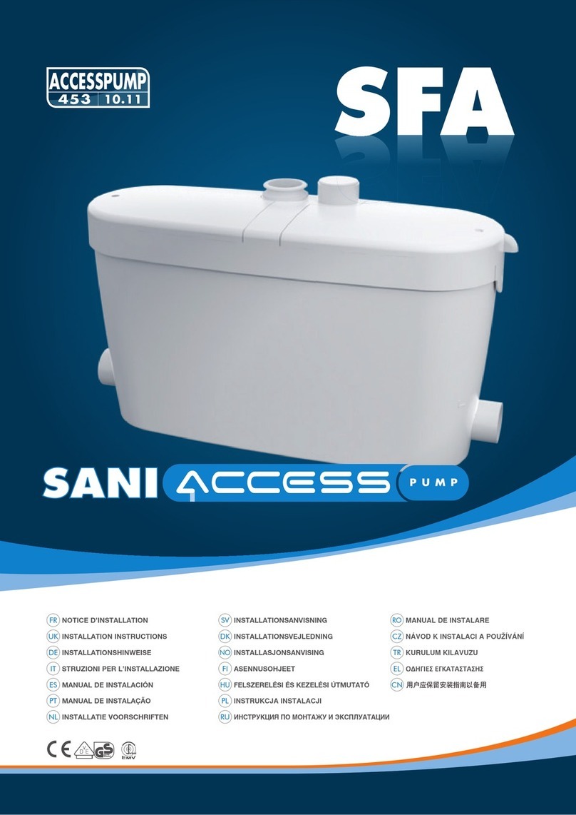
SFA SANICUBIC Classic User manual

1
11.10
IND1
15 0
A lire attentivement et à conserver à titre dʼinformation • To be read and kept for information
Bitte aufmerksam durchlesen und aufbewahren • Da leggere attentamente e conservare a titolo di informazione
Leer atentamente y conservar a título de información • Leia atentamente este manual e guarde-o a título de informação
Dit document goed doorlezen en bewaren • Läs igenom anvisningen noga och spara den
Käyttäjän on säilytettävä nämä ohjeet myöhempää tarvetta varten •
Do uważnego przeczytania i zachowania tytułem informacji
ÇÌËχÚÂθÌÓ ÔÓ˜ËÚ‡Ú¸ Ë ÒÓı‡ÌËÚ¸ ‚ ÔÓfl‰Í ËÌÙÓχˆËË •
NOTICE D'INSTALLATION • INSTALLATION INSTRUCTIONS • INSTALLATIONSHINWEISE
ISTRUZIONI PER L'INSTALLAZIONE • INSTRUCCIONES DE INSTALACIÓN • MANUAL DE INSTALAÇÃO
INSTALLATIE VOORSCHRIFTEN • INSTALLATIONSANVISNING • ASENNUSOH EET
INSTRUKC A INSTALAC I • ИНСТРУКЦИЯ ПО УСТАНОВКЕ • MANUAL DE INSTALARE
geprüfte
Sicherheit
CNCZ
RORURUFISVNLPTESITDEUK
FR
•
•
9257 N150 SANICUBIC NOTICE:5622 NOTICE N°129 EXE 19/11/10 13:35 Page 1

6
1
11
10
9
8
7
6
5
4
3
2
1
0
80 100 120 140 160 180 200 220 240 260 280 300 320 340 360
max 100 m
max 110 m
max 90 m
max 80 m
max 70 m
4m
3m
2m
1m
1
%
1
%
1
%
1
%
1
%
1
%
8m
7m
6m
5m
max 60 m
max 50 m
max 40 m
1
%
1
%
1
%
max 11m
9m
max 30 m
max 20 m
1
%
1
%
10m
max 10 m
1
%
OK
SFA
SFA
SFA
7
1 1+ 2
DN 40/50/100/110* DN 40/50/100/110*
DN 40/50/100/110
DN 50
DN 50
DN 40/50/100/110
* cf. 8b
2Cx 8 Dx 4 Ex 2
40/60 32/50
Jx 4
100/120
Kx 1 Lx 2
Fx 2
Ax 2
Bx 2
*
*
Hauteur (m) • Vertical Height (m)
Fördenhöhe (m) • Altezza (m) • Højde (m)
Opvoerhoogte (m) • Altura (m) • Высота (м)
Wysokość (m) pionowa • Korkeus (m)
Înălţime • Lyfthöjd • Výška čerpání (m) • (m)
Gx 2
Hx 2
Nx 1
Ox 1
10/16
2 m
OPTION
WAHL
OPZIONE
OPTIE
OPCIÓN
OPÇÃO
AFLØB
EXTRA
VALGFRITT
ОПЦИЯ
WO
Mx 1
9257 N150 SANICUBIC NOTICE:5622 NOTICE N°129 EXE 19/11/10 13:35 Page 2

88b
8e
8d
1
8f
SFA
8h
9SANICUBIC® Classic
Société Française dʼAssainissement
EN 12050-1
R300 LC
220-240 V - 50 Hz
3000 W -
geprüfte
Sicherheit
3
12
3
2
3
1
2
L
D
D
F
D
D
F
D
DN 50
J
J
D
C
C
8g
L
L
B
A
G
H
12
O
N
9257 N150 SANICUBIC NOTICE:5622 NOTICE N°129 EXE 19/11/10 13:36 Page 3

DESCRI TIF
SANICUBIC® Classic est une station de rele-
vage conçue pour évacuer les effluents de
petites unités à usage privé ou commercial.
Respecter toutes les règles dʼinstallation
et dʼentretien décrites dans cette notice.
En particulier les indications repérées par :
" " indication dont le non-respect
pourrait entraîner des risques pour
la sécurité des personnes,
" " indication avertissant de la présence
dʼun risque dʼorigine électrique,
" " instructions réservées exclusivement
aux professionnels qualifiés,
"ATTENTION" indication dont le
non-respect pourrait entraîner des
risques pour le fonctionnement de
lʼappareil.
Pour tous renseignements complémentaires,
veuillez vous adresser à notre service
clients.
RINCI E DE FONCTIONNEMENT
SANICUBIC® Classic contient 2 pompes
indépendantes. Chacune de ces pompes
est équipée dʼun système de dilacération
haute performance.
Les 2 pompes fonctionnent chacune à leur
tour de manière alternée. En cas de
fonctionnement anormal, les 2 moteurs
fonctionnent simultanément (ou si lʼune
des pompes est défectueuse, lʼautre prend
le relais).
La cuve du SANICUBIC® Classic est
munie de 2 tubes plongeurs qui
commandent lʼun la marche des moteurs,
lʼautre le système dʼalarme.
- Tube plongeur long (fonctionnement
normal) : dès que les effluents atteignent
le niveau dʼenclenchement du tube long
dans la cuve, le système de pompage se
met en marche.
- Tube plongeur court (fonctionnement
anormal) : si les effluents atteignent le
niveau haut dans la cuve, un contact est
établi, une marche forcée du système de
pompages auxiliaires est enclenchée. Ce
contact déclenche une alarme visuelle et
sonore. La LED de lʼalarme générale sur
le clavier du SANICUBIC® Classic devient
rouge.
Le SANICUBIC® Classic peut être équipé
en option d'un module d'alarme déporté
(filaire) qui reproduit des signaux optiques
et sonores du fonctionnement de l'appareil.
1
LISTE DES IECES FOURNIES
2
DIMENSIONS
3
DONNEES TECHNIQUES
SANICUBIC® Classic
Type R300 LC
Hauteur de refoulement maximum 11 m
Tension 220-240V
réquence 50 Hz
Volume 47 l
Puissance absorbée maximale 3000 W
Intensité absorbée maximale 13 A
Classe électrique I
Température moyenne
des eaux admissibles 35°C
Température maximum
par intermittence (max 5 min) 70°C*
Indice de protection IP67
Poids net (accessoires inclus) 30 kg
*Cycles d'évacuation chaude de lave-vaisselle et lave-linge
4
DOMAINE D’A LICATION
Effluents domestiques de la maison
(les débits dʼarrivées cumulés ne devant
pas dépasser 80% de ceux indiqués sur
le graphique ).
6
5
RACCORDEMENT DE
LʼEVACUATION
Déposez le ou les cache-embouts à
l'arrière de l'appareil (cf ).
Grâce au système de dilacération qui
équipe chaque pompe, la conduite
dʼévacuation peut être réalisée avec un
tuyau DN 50.
Le coude de refoulement se trouve au
centre de l'appareil, à l'arrière (cf ).
Reliez-le par le manchon au tuyau
ascendant et fixez-le avec les colliers.
Chaque pompe du SANICUBIC® Classic
est équipée de clapets anti-retour.
Pour vannes et reflux voir paragraphe .
RACCORDEMENT DʼAPPAREILS
SANITAIRES AUX ENTRÉES
BASSES
Si vous souhaitez installer une
douche ou une baignoire au
même niveau que le SANICUBIC®
Classic, vous devez impérativement
veiller à placer la partie supérieure des
bondes dʼévacuation des appareils à
une hauteur minimum de 250 mm.
RACCORDEMENT ENTRÉES
DN 40/50
Entrées basses (cf )
Entrées hautes (cf )
• Découper l'extrémité de l'entrée DN50
avec une scie
• Découper le manchon au diamètre
du tuyau : DN 40 ou DN 50 (cf )
• ixer le manchon sur l'entrée et sur
le tuyau à l'aide des colliers.
RACCORDEMENT DE LʼENTRÉE
DN 100/110
Entrées basses (cf )
1- Enlever le bouchon de lʼentrée latérale.
2- ixer le manchon avec le collier .
3- Enfoncer le tube DN 100/110 dans
lʼautre extrémité du manchon et le fixer
avec lʼautre collier .
Entrées hautes (cf )
1- Découper lʼextrémité haute de lʼentrée
DN100 avec une scie.
2- ixer le manchon avec le collier .
3- Enfoncer le tube DN 100/110 dans
lʼautre extrémité du manchon et le fixer
avec lʼautre collier .
RACCORDEMENT DE LʼEVENT
1- EVENT DU SANICUBIC® Classic
Une des entrées hautes DN50 doit
être dédiée à la ventilation. La
conduite dʼaération doit être liée au
toit.
Découper lʼextrémité dʼune des
entrées DN50 avec une scie.
Puis fixer le manchon avec le
collier .
Enfoncer le tube DN50 dans lʼautre
extrémité du manchon et le fixer
avec lʼautre collier .
C
C
D
8f
J
F J
8b
8c
D
D
D
1
8g
8b
3
8d
8a
2
8d 2
8d 1
8d
8e
8e 1
F J
8e
J
FR
COURBE DE ERFORMANCES
Exemple: La pompe P1 travaille normale-
ment. A 5 m de refoulement elle évacue
160 l/min. A la moindre insuffisance de la
pompe P1 ou lors d'une arrivée d'eaux
usées trop importante, la pompe P2 se
met en marche. Le débit monte alors à
environ 275 l/min, jusqu'à normalisation.
6
Les numéros renvoient aux schémas explicatifs
EQUIVALENCE HAUTEUR/
LONGUEUR EVACUATION
7
INSTALLATION
La mise en service et la
maintenance de cet appareil doivent être
effectuées par un professionnel qualifié.
Veuillez vous référer à la norme
d'installation EN 12056.
RÉGLEMENTATION
1- Attention : le local technique où sera
installé SANICUBIC® Classic doit être
de dimension suffisante pour aménager
un espace de travail de 600 mm mini-
mum autour et au-dessus de lʼappareil
de façon à faciliter une maintenance
éventuelle. Ce local doit être éclairé,
suffisamment ventilé et protégé contre
le gel.
2- Des vannes dʼarrêts (non fournies)
doivent être installées sur les entrées
dʼeffluents ainsi que sur la conduite
dʼévacuation.
3- Cette conduite dʼévacuation doit être
conçue pour éviter tout reflux des
égouts (voir exemples dessin ).
Grâce à lʼinstallation dʼune boucle
anti-retour, située au-dessus du niveau
de reflux, le reflux est évité.
Remarque : Sauf indications locales
contraires, le niveau de reflux
correspond au niveau de la voirie
(routes, trottoirs…). Continuez ce
conduit après la boucle anti-retour par
le tuyau d'un diamètre supérieur.
4- Lʼinstallation dʼune pompe auxiliaire
pour le drainage éventuel du local
technique (en cas dʼinondation) est
recommandée.
5- La station de relevage doit être aérée
par-dessus le toit.
6- La station de relevage doit être fixée au
sol (voir paragraphe ).
8h
3
8g
8a
8
9257 N150 SANICUBIC NOTICE:5622 NOTICE N°129 EXE 19/11/10 13:36 Page 4

ATTENTION : ne pas connecter un casse-vide à la
conduite d'aération, la conduite doit rester ouverte pour
le bon fonctionnement de lʼappareil.
2- MISE À L'AIR DE LA PARTIE ÉLECTRIQUE:
Connecter le tuyau PVC cristal 8/11 fourni au clavier situé
sur le Sanicubic. L'autre extrémité de ce tuyau doit se
situer entre 1m et 2m au-dessus de l'appareil pour éviter
que l'eau rentre dans la partie électrique en cas
dʼinondation.
Attention : ne pas pincer le tuyau.
VIDANGE
Le SANICUBIC® Classic est muni de 2 bouchons ( ).
Débrancher l'alimentation électrique de l'appareil
1- Déclipser le capot.
2- Enlever 1 des 2 bouchons.
3- Passer le tuyau dʼaspirateur (à eau) pour vidanger lʼappareil.
Le diamètre de passage est de 40 mm.
4- Une fois la vidange terminée, replacer le bouchon puis le
capot.
FIXATION AU SOL DE LA CUVE
SANICUBIC® Classic possède des dispositifs de fixation au sol
lʼempêchant de tourner ou de bouger.
1- Placer lʼappareil à lʼendroit souhaité.
2- Tracer le contour de lʼappareil.
3- Positionner et fixer au sol les équerres selon le plan de
perçage ( )
4- Replacer lʼappareil.
5- ixer lʼappareil avec les vis .
RACCORDEMENT ÉLECTRIQUE
1- Lʼinstallation électrique doit être réalisée par un électricien qualifié.
Lʼinstallation électrique doit correspondre aux normes en vigueur
dans le pays.
2- Lʼalimentation doit être réalisée en classe 1. Lʼappareil doit être
raccordé à un boîtier de connection relié à la terre. Le circuit
dʼalimentation électrique doit être protégé par un disjoncteur
différentiel haute sensibilité de 30 mA calibré à 20 A.
Ce raccordement doit servir exclusivement à lʼalimentation du
SANICUBIC® Classic.
Si le câble de cet appareil est endommagé, il doit être
remplacé par le fabricant ou son SAV afin dʼéviter tout danger.
B
1
8h
8h
1
8g
8g
8i
FONCTIONNEMENT DE L’ALARME
1/ Alarmes générales :
Alarme de niveau :
Si le niveau dʼeau à lʼintérieur de lʼappareil est anormalement haut :
déclenchement de la sirène + allumage de la LED rouge alarme +
démarrage de lʼautre moteur 3 secondes après (voir visuel clavier
de commande).
Alarme temporelle :
Si un des 2 moteurs marche pendant plus de 1 minute :
déclenchement de la sirène + allumage de la LED rouge alarme +
démarrage de l'autre moteur 3 secondes après.
2/ RAZ (Remise A Zéro) alarmes générales :
Si le problème ayant déclenché une des alarmes ci-dessus disparaît,
la sirène sʼarrête, mais la LED rouge dʼalarme reste allumée pour
mémoriser le fait que le système a rencontré un problème.
La touche “RAZ alarme” du clavier permet dʼarrêter la sirène dans
tous les cas, mais elle ne permettra dʼéteindre la LED rouge que
si le problème ayant déclenché lʼalarme a été résolu. Ceci permet
dʼéviter quʼun système soit “abandonné” en défaut.
9
ALARME DE LʼAPPAREIL
LED
moteur 1
LED
moteur 2 LED
“Alarme”
LED
“secteur”
“marche
forcée”
mot 1
“marche
forcée”
mot 2
“RAZ”
Alarme
MISE EN SERVICE
1- Une fois les raccordements hydrauliques et électriques
effectués, vérifier lʼétanchéité des raccordements en
laissant couler de lʼeau successivement par chaque entrée
utilisée. Sʼassurer du bon fonctionnement de lʼappareil en
effectuant un essai en eau de 2 cycles de démarrage au
minimum.
2- ATTENTION : ne pas faire fonctionner les moteurs
en marche forcée (en appuyant sur les boutons
poussoirs du boîtier) avant dʼavoir mis les pompes en
eau. Un fonctionnement à sec détériore le système de
broyage.
11
UTILISATION
1- SANICUBIC® Classic est conçu pour évacuer les eaux
usées dʼorigine domestique. Toute autre application
entraînerait lʼannulation de la garantie.
Ne jamais rejeter serviettes, préservatifs, articles
dʼhygiène, huiles, solvants, déchets, acides, bases,
autres liquides potentiellement explosifs, corrosifs…
2- ATTENTION : En cas de coupure de courant, arrêter
tout écoulement dʼeau sur les appareils reliés au
SANICUBIC® Classic.
3- Ne pas installer/utiliser dans une zone à risque
d'explosion.
12
CONFORMITE AUX NORMES
• SANICUBIC® Classic est conforme à la norme EN 12050-1
(station de relevage pour effluents contenant des matières
fécales) ainsi quʼaux directives Européennes sur les produits
de construction, la sécurité électrique et la compatibilité
électromagnétique.
10
MAINTENANCE
Le bon fonctionnement de la station de relevage doit être
vérifié visuellement une fois par mois et doit régulièrement
être contrôlé par un personnel qualifié (annuellement). Si
toutefois vous rencontriez des problèmes techniques,
demandez conseil au service après-vente. Si le câble de
cet appareil est endommagé, il doit être remplacé par le
fabricant ou son service après vente pour éviter tout danger.
13
GARANTIE
SANICUBIC® Classic est garanti 2 ans pièces et main-dʼœuvre
dans la mesure où lʼinstallation et lʼutilisation sont
conformes à la présente notice.
14
9257 N150 SANICUBIC NOTICE:5622 NOTICE N°129 EXE 19/11/10 13:36 Page 5

DESCRI TION
The SANICUBIC® Classic is a lifting station
designed to evacuate effluent from small
private or commercial units.
Please comply with all the installation and
maintenance specifications set out in these
instructions, and especially the information
marked with the following signs:
" " ailure to comply with this
information could entail safety
hazards for personnel,
" " Information warning of the presence
of an electrical hazard,
" " Instructions only for qualified
professional specialists,
"WARNING" ailure to comply with this
information could affect the normal
operation of the equipment.
Please contact our Customer service for
further information.
SANICUBIC O ERATING
RINCI LE
SANICUBIC® Classic contains 2 separate
pumps. Each of the pumps is fitted with a
high-performance maceration system.
The 2 pumps operate alternately. In the
event of inflow overload, both motors run
at the same time (or if one of the pumps is
faulty, the other one takes over).
The SANICUBIC® Classic tank is fitted with
2 dip tubes; one tube controls motor
operation, and the other one controls the
alarm system.
- Long pickup tube (normal operation):
as soon as the waste water level in the
tank reaches the triggering point in the
long tube, the pumping system starts up.
- Short pickup tube (inflow overload
operation): if the waste water level in the
tank reaches the upper point, a contact is
closed, and the auxiliary pumping system
is triggered. The contact also sets off an
audible and visual alarm. The general
alarm LED on the SANICUBIC® Classic
control panel switches to red. The
SANICUBIC®Classic can be fitted with an
optional remote alarm unit (cabled) that
monitors the equipmentʼs operational status
by producing accoustic and visual signals.
1
LIST OF ARTS SU LIED
2
DIMENSIONS
3
TECHNICAL DATA
SANICUBIC®Classic
Type R300 LC
Maximum discharge head 11 m
Voltage 220-240V
requency 50 Hz
Volume 47 l
Maximum power input 3000 w
Maximum current input 13 A
Electrical classification I
Ave water temp for optimum performance 35°C
Maximum temperature intermittent
(max 5 min) 70°C*
Protection index IP67
Net weight (including accessories) 30 kg
*
Hot water drain cycles from dishwashers or washing machines
4
FIELD OF A LICATION
Household waste water (the combined
inputs must not exceed 80% of those
shown in the graph ).
6
5
INSTALLATION
The SANICUBIC® Classic must be instal-
led in compliance with standard EN12056.
The equipment must be commissioned
and maintained by a qualified professional
specialist.
Please refer to installation standard
EN 12056.
REGULATIONS
1- Attention: the space in which the
SANICUBIC® Classic is to be installed
must be large enough to leave at least
600 mm of working room around and
above the unit to facilitate such
maintenance work as may be required.
There must be sufficient lighting, and it
must be sufficiently well ventilated and
protected from freezing.
2- Isolating valves (not supplied) must
be fitted on waste inlets (especially
the 110mm inlets) and on the
discharge to ensure that any
service/maintenance may be carried
out safely).
3- The discharge pipe must be fitted so as
to avoid all back flow from the drainage
system (see the examples in drawing
). Back flow can be avoided by
installing an anti-back flow riser
reaching a high point above the
maximum back flow level.
Comment: In the absence of local
information to the contrary, the
maximum back flow level corresponds
to street level (roadway, pavements,
etc.). Continue the discharge pipework
after the anti-backflow riser, using a
larger diameter pipe.
4- If the Sanicubic is installed in a space
such as a pit for example, we would
recommend the fitting of a bilge pump
in case of flooding.
5- The lifting station must be vented with
an outlet at roof level.
6- The lifting station must be fixed to the
floor (see paragraph ).
CONNECTING THE DISCHARGE
PIPE
Remove the end cover or covers from the
back of the unit (cf. ).
As each pump is fitted with a macerator
system, an ND50 mm discharge pipe can
be used.
The discharge bend is at the centre of the
unit, at the back (cf. ). Use the sleeve
to connect it to the riser pipe and fix it
in place with the collars.
D
8b
1
8h
8g
8b
8g
8a
8
Each pump in the SANICUBIC® Classic
unit is fitted with check valves.
See paragraph regarding control
valves and back flow.
CONNECTING SANITARY
EQUIPMENT TO THE LOWER
INLETS
If you want to install a shower or a
bath at the same level as the
SANICUBIC® Classic, you must
make sure that the upper parts of the
plugholes on the sanitary equipment are
at least 250 mm above the lower inlets.
CONNECTING THE INLETS ND 40/50
Lower inlets (cf. )
Upper inlets (cf. )
• Cut off the end of the ND 50 inlet with a
saw
• Cut the sleeve to suit the pipe
diameter: ND 40 or ND 50 (cf. )
• ix the sleeve on the inlet and on the
pipe, using the collars.
CONNECTING THE ND 100/110 INLET
Lower inlets (cf. )
1- Remove the plug from the side inlet.
2- ix the sleeve in place using the
collar. .
3- ully insert the ND 100/110 tube in the
other end of the sleeve and fix it in
place using the other collar. .
Upper inlets (cf. )
1- Cut off the upper end of the ND 100
inlet with a saw.
2- ix the sleeve in place using the
collar .
3- ully insert the ND 100/110 tube in the
other end of the sleeve and fix it in
place using the other collar .
CONNECTING THE VENT
1- VENT OF SANICUBIC® Classic
One of the upper ND50 inlets must
be used for the vent. The vent pipe
must be fitted up to roof level.
Cut off the end of the one of the ND
50 inlets with a saw.
Then fix the sleeve in place using
the collar .
Fully insert the ND 50 tube in the
other end of the sleeve and fix it in
place using the other collar .
WARNING: Do NOT fit air admittance
valve on the top of the air vent pipe.
The vent must be an open vent or the
unit will not operate.
2- VENTING THE ELECTRICAL PART
Connect the 8/11 clear PVC tubing
supplied to the keyboard on the
Sanicubic. The other end of this
tubing must be located between 1m
and 2m above the device to avoid
water getting into the electrical part
in the event of flooding.
Important: do not pinch the tubing.
8a
3
8d
D
D
2
8d
1
8d
C
C
D
8f
J
J
F
8e 2
J
J
F
8e 1
8e
8d
8c
UK
ERFORMANCE CURVE
Example: Pump P1 is operating normally.
It discharges 160 l/min at a pumping
height of 5 m. If pump P1 shows any
signs of weakness or if the waste water
inflow is too great, pump P2 starts up. The
output is then increased to about 275
l/min, until the situation returns to normal.
6
The numbers refer to the explanatory diagrams.
RATIO OF HEIGHT/LENGTH
FOR DISCHARGE
7
Fully illustrated step by step
instructions are downloadable
on www.saniflo.co.uk
9257 N150 SANICUBIC NOTICE:5622 NOTICE N°129 EXE 19/11/10 13:36 Page 6

ALARM O ERATION
1/ General alarms:
High level alarm:
If the water level in the unit is abnormally high: the buzzer is
triggered and the red LED comes on; the other motor starts up
3 seconds later (see the illustration showing the control
keyboard).
Temporary alarm:
If one of the 2 motors runs for more than 1 minute: the buzzer is
triggered and the red alarm LED comes on; the other motor starts
up 3 seconds later.
2/ Resetting the general alarms:
If the problem that has triggered one of the alarms referred to
above ceases, the buzzer stops, but the red alarm LED stays
on to memorize the fact that the system has met with a
problem.
The “Reset alarm” key on the keyboard is used to switch the
buzzer off in all cases, but it only switches the red LED off if
the problem that triggered the alarm has been dealt with. This
avoids the risk of having a system “abandoned” in fault status.
UNIT ALARM
9
DRAINING
The SANICUBIC® Classic unit is fitted with 2 plugs ( ).
Disconnect the unit from the power supply.
To drain the unit
1- Unclip the cover.
2- Remove one of the 2 plugs.
3- Insert a wet utility vacuum cleaner pipe to drain the unit. The
port diameter is 40 mm.
4- When the unit has been drained, put
the plug and then the cover back in place.
FIXING THE SANICUBIC UNIT TO THE FLOOR
The SANICUBIC® Classic unit is equipped with fittings to hold it
on the floor and
prevent it from turning or moving.
1- Place the unit on the desired spot.
2- Draw the outline of the unit.
3- Position the brackets and fix them to the floor as shown on the
template diagram ( ).
4- Put the unit back in place.
5- ix the unit in place with the screws.
ELECTRICAL CONNECTIONS
1- The electrical installation work must be carried out by a
qualified electrician.
The electrical installation must comply with the standards in
force in the country concerned
2- The power supply must be of the class 1 type. The unit must be
connected via an earthed connection box. The electric power
circuit must be protected by a high-sensitivity 30 mA differential
circuit breaker set at 20 A. The connection must be used solely
to power the
SANICUBIC® Classic
. If the power lead on the unit
is damaged, it must be replaced by the manufacturer or its
after-sales service to avoid all danger.
1
8g
8g
1
8h
8h
8i
motor 1
LED motor 2
LED “Alarm”
LED “Mains”
LED
motor 1
“Override”
motor 2
“Override”
“RESET”
Alarm
CONFORMITY WITH STANDARDS
• SANICUBIC® Classic complies with standard EN 12050-1 (lift
station for household waste containing faeces) and with the
European directives covering construction products, electrical
safety and electromagnetic compatibility
This unit must be installed and used in compliance with
European installation standard EN12056 and with local
requirements.
10
COMMISSIONING
1- Once the plumbing and electrical connections have been
made, check that the connections are watertight by
letting water flow successively through each inlet used.
Make sure that the unit is operating correctly by carrying
out at least two start cycles with water to test the system.
2 - WARNING! Do not operate the motors in override
status (by pressing the pushbuttons
on the control box) until the pumps have been filled
with water. Operation without water damages the
maceration system.
11
USE
1- The SANICUBIC® Classic unit is designed to drain off
household waste water. Any other use will invalidate the
guarantee. Do not dispose of sanitary towels, condoms,
hygiene articles, oils, solvents, acids, or any other poten-
tially corrosive or explosive liquids etc., via the unit.
2- WARNING: In the event of a power failure, stop
draining any water from the equipment connected
to the SANICUBIC® Classic unit.
3- Do not install or use the unit in a zone where there is a
risk of explosion.
12
GUARANTEE
The SANICUBIC® Classic unit is guaranteed for two years
(parts and labour) provided that it has been installed and
used in compliance with the present instructions.
14
MAINTENANCE
A visual check of the lift station must be made once a month
to make sure it is operating correctly, and the installation
must be inspected regularly (once a year) by a qualified
person. Meanwhile if encounter technical problems, please
ask our after-sales service for advice. If the power supply
cable of the unit is damaged, it must be replaced by the
manufacturer or its after-sales service to avoid all danger.
13
9257 N150 SANICUBIC NOTICE:5622 NOTICE N°129 EXE 19/11/10 13:36 Page 7

BESCHREIBUNG
SANICUBIC® Classic R300 ist eine zweimo-
torige Grau- und Schwarzwasserpumpe für
Sanitäranlagen.
Bitte halten Sie die Installations-,
Nutzungs- und Wartungsvorschriften dieser
Einbauanleitung ein. Das gilt besonders für
Textpassagen mit den folgenden
Hinweiszeichen.
Nichtbeachtung: Sicherheitsrisiken für
den Anlagennutzer.
Nichtbeachtung: Risiken durch
elektrischen Strom.
Angaben, für qualifiziertes
achpersonal (s. a. Hinweise
N°150-PRO” für Einbau und Betrieb).
Nichtbeachtung kann ehlfunktionen
hervorrufen.
Bei Unklarheiten rufen Sie bitte
unseren Service an.
1
ABMESSUNGEN
557 mm b x 407,5 mm h x 492 mm t
Details Sonderseite II
3
TECHNISCHE DATEN
Typ R300 LC
örderhöhe (max.) 11 m
Höchstdurchsatz bei 11 m örderhöhe ca. 100 l/min.
Betriebsspannung 220-240V
requenz 50 Hz
Behältervolumen 47 l
Energieaufnahme (max.) 3000 W
Stromstärke (max.) 13 A
Schutzklasse I
Mittlere zulässige Abwassertemperatur 35°C
Abwasser-Höchsttemperatur zeitweilig
(max 5 min) 70°C*
Isolationsklasse IP67
Nettogewicht (einschl. Montageteile) 30 kg
*Heißwasser-Entleerungszyklen von Wasch- und Spülautomaten
4
ANWENDUNGSBEREICH
Abwasserentsorgung bei
Sanitärrenovierung in Wohn- und
Kleingewerbeanlagen.
Aus Sicherheitsgründen planen Sie
bitte mit 80 % des in genannten
Idealwertes ein. 6
5
EINBAU
Installieren Sie SANICUBIC® Classic
nach den handwerklichen Richtlinien
unter Einhaltung der Norm EN 12056.
Inbetriebnahme und Wartung durch
eine qualifizierte achkraft.
Besondere Hinweise und
Ratschläge
1- Platzbedarf des SANICUBIC® Classic
557 mm b x 407,5 mm h x 492 mm t.
ür leichte Zugänglichkeit (DIN)
rechnen Sie bitte ca. 600 mm auf allen
Seiten.
Die Vorgaben der EN 12056 müssen
bei der Installation beachtet werden.
2- Vor den Abwassereinläufen und nach
dem örderstutzen bitte geeignete
Absperrschieber anbringen.
3- Installieren Sie die örder- bzw.
Druckleitung DN 50 so, dass Rücklauf
aus der Abwasserkanalisation
vermieden wird ( Sonderseite II,
“Zeichnungen”), mit einer Rohrschleife
über die Rückstauebene.
4- Nach der Rohrschleife führen Sie die
weitere Ableitung im nächsthöheren
Durchmesser aus, z. B. DN 60.
5- Im alle einer Schachtmontage (Grube)
sichern Sie den SANICUBIC Pro mittels
einer Tauchpumpe gegen Überflutung
ab.
6- SANICUBIC® Classic bitte über
Dachoberkante entlüften.
3
8g
8a
8
Anschluss von Sanitärgeräten an
tiefliegende Einlauföffnungen
Bei Installation von Dusche
oder Badewanne auf
Einbauebene des SANICUBIC®
Classic muss die Oberkante der
Abwasserableitungen mindestens
250 mm über Boden liegen.
Anschluss der Abwasserein- oder
Förder- Druck- und Entlüftungsrohre.
Ein- und Ableitungsöffnungen rechts und
links oben, am SANICUBIC® Classic liegen
unter geklipsten Abdeckungen .
Anschluss der Förder- bzw.
Druckleitung
Zerkleinerungsvorrichtungen an den
Pumpenansaugöffnungen ermöglichen die
Druckleitung in DN 50.
Nehmen Sie die Ab- bzw. Einleitungs-
stutzenverkleidung ( ) an der
Geräteoberseite ab.
Der Druck- bzw. Förderstutzen
Y-Bogen, befindet sich in Gerätemitte,
hinten .
Anschluss über Stutzen an das
Steigrohr, mit geräuschdämpfenden
Schellen.
SANICUBIC® Classic hat eingebaute
Rückflussklappen.
Sperrschieber, Rückflussverhinderer
s. Abschn. .
Anschluss von Einleitungen DN 50
• tief liegend -
Sägen Sie die Kuppe des DN 100
Anschlussstutzens ab.
Es entsteht ein DN 50-Einlauf.
Vor Befestigen des Überleitungsstutzens
schneiden sie ihn auf DN 50 zurecht.
D
8b
8d 1
8d
2
1
8g
J
1
3
8a
8e
8c
8g
8c
DE
Nummern im Text verweisen auf Illustrationen Seite I und II “Zeichnungen”
ABHÄNGIGKEIT FÖRDERHÖHE / -
DISTANZ: Sonderseite II, Zeichnungen
7
FUNKTIONS RINZI
SANICUBIC® Classic enthält zwei
Pumpen mit Hochleistungszerkleinerer.
Die beiden Pumpen funktionieren
abwechselnd. Bei plötzlich erhöhtem
Abwassereinlauf arbeiten die Pumpen
zeitweise gleichzeitig, oder bei Ausfall
einer Pumpe hält die andere die
Entleerungsfunktion aufrecht.
SANICUBIC® Classic enthält zwei
Schaltelemente (Tauchrohre).
Tauchrohr 1 (lang)
• Normalbetrieb der Anlage.
Sobald das Abwasserniveau den oberen
Schaltpunkt erreicht: Entleerungszyklus
“Ein”!
Am unteren Schaltpunkt:
Pump-bzw. Motorfunktion: “Aus”!
Tauchrohr 2 (kurz)
• Meldung ungewöhnlichen Betriebs.
Bei erheblichem Wasserstand in der
Pumpe schaltet die Betriebselektronik die
zweite Pumpe zu. Hierbei wird die
Warnleuchte auf dem Tastenfeld und ein
akkustisches Warnsignal eingeschaltet.
LED-Warnlicht auf dem Tastenfeld des
SANICUBIC®Pro leuchtet rot.
Gleichzeitig signalisiert ein Akkustiksignal den
ungewöhnlichen Betriebszustand.
Die Schaltelektronik des SANICUBIC®
Classic übermittelt per Hochfrequenz
Betriebsarten und -zustände an einen nicht
ortsfesten Betriebsmelder. (siehe auch
unktion und Normsignale auf dem H -
Betriebsmelder).
14
Beispiel: Pumpe P1 arbeitet “normal”. Bei 5 m Höhe werden 160 l/min.
gefördert. Bei Leistungsabfall von Pumpe P1, oder plötzlich
höherem Abwassereinlauf springt P2 ein. Die örderleistung steigt
auf ca. 275 l/min. bis zum Wiedereintritt des Normalbetriebs.
Der Zwischenfall wird auf dem Tastenfeld angezeigt, und an den
Betriebssmelder [H -Empfänger] weitergeleitet.
LEISTUNGSDIAGRAMM
6
11
10
9
8
7
6
5
4
3
2
1
0
80 100 120 140 160 180 200 220 240 260 280 300 320 340 360
ördenhöhe (m)
P1 + P2
P1
9257 N150 SANICUBIC NOTICE:5622 NOTICE N°129 EXE 19/11/10 13:36 Page 8

ELEKTROANSCHLUSS
Elektroarbeiten für Ihren SANICUBIC® Classic sind von
einem zugelassenen Elektrofachmann vorschriftsmäßig
auszuführen. Bewahren Sie die Rechnung (für
Versicherung, Garantiefälle u. dergl.) gut auf!
Der Anschluss muss den Errichtungsnormen Ihres Landes
genügen, in Deutschland z. B. DIN VDE 0100, Teil 701 ( eucht-
und Nassräume, ehlerstromschutzschalter, Nennauslösestrom
von 30 mA, usw.).
Die Stromversorgung muss der Schutzklasse Ientprechen.
Korrekte Erdung prüfen [38 Ω].
Das Gerät muß durch eine allpolige Trennvorrichtung mit einem
Kontaktöffnungsabstand von mindestens 3mm vom Netz
getrennt werden.
8i
HIER WERDEN SIE EIN SANICUBIC®ROFI
Die LEDs auf dem Bedienerfeld werden Sie rasch vers-
tehen. Bitte erklären Sie das alles auch Ihrem
Kunden.
LEUCHTANZEIGEN
Armaturenbrett, Bedienfeld und Betriebsanzeigen
1. Normalbetrieb,
Anzeige der Betriebszustände im Sanicubic®Classic.
Die Motorpumpen arbeiten im Wechsel. Im Normalbetrieb
läuft nur eine Motorpumpe.
Start/Stop der Motorpumpen ist wasserstandsgesteuert.
Wasserstand hoch: Pumpe 1 bzw. 2
Wasserstand tief: kurzer Nachlauf, dann 1 bzw. 2
Pumpe läuft: Betriebsanzeige (LED) 1 bzw. 2
2.1 Zeitliche Kontrolle – Wasserstand hoch (Dauer)
Warnsignal – Zwangszuschaltung zweite Motorpumpe
Leistungsabfall der diensthabenden Motorpumpe (verstopft,
oder langanhaltendes hohes Abwasservolumen im Behälter).
In der Praxis: Abwasser im Pumpenbehälter steigt über das
kritische Niveau, trotz einer Minute Volllastbetrieb der
Pumpe.
2.1.1 Automatische Zuschaltung der zweiten Motorpumpe
Signalton Buzzer
LED-Betriebsanzeige Motorpumpe 1 bzw. 2
Motorpumpe 2 bzw. 1
bis zum Absenken auf Kontrollpunkt
“Behälter entleert, beide Pumpen
abschalten!” 2 und 1
2.2 Niveauschaltung – kritisches Wasservolumen
Warnsignal – volumengesteuerte Zuschaltautomatik
Im Praxisbetrieb: Die elektronische Volumenmessung im
SANICUBIC® Classic bleibt länger als vier Sekunden aktiviert.
2.2.1 Automatische Zuschaltung der zweiten Motorpumpe
Signalton Buzzer
LED-Betriebsanzeige Motorpumpe 1 bzw. 2
Motorpumpe 2 bzw. 1
bis zum Abschalten des Volumenmelders (als zweifache
Sicherheit) und Absenkung des Wasserstands auf
Abschaltniveau: Beide Motorpumpen: 2 und 1
3. Warnanzeigen-Rückstellung
3.1 ehlfunktions-Risiken lösen Warnsignale aus. Nach
Bereinigung einer jeweiligen Risikosituation wird jedoch nur
das Akustiksignal aufgehoben.
3.2 Zur Erinnerung leuchtet das Alarm-LED weiter.
3.3 Die Rückstelltaste im Tastenfeld (neben ) schaltet die
Akustiksignale aller Risikofälle ab.
Bis zur Bereinigung des gemeldeten Zwischenfalls bleibt
jedoch das Warn-LED auf
9
( ortsetzung)
• oben liegend -
Sägen die DN 50-Kuppe am Einlauf ab. Vor Befestigen des
Stutzens schneiden sie ihn auf DN 50 zurecht. Siehe
Illustration Sonderseite 2, Zeichnung .
VARIANTE : EINLAUF IN DN 40
• Den Stutzen auf DN 40 zurecht schneiden - .
ANSCHLUSS VON DN 100-EINLEITUNGEN
• tief liegend - cf
1- Insertstopfen am Seiteneinlauf abnehmen, aufbewahren.
Damit kann später ein DN 50-Stutzen für einen evtl.
unbenutzen, oberen DN 100 Einlauf hergestellt werden.
2- Befestigen Sie den Stutzen mit der Schelle .
3- Stecken sie das DN 100- allrohr in den Stutzen und
befestigen Sie es mit der zweiten Schelle .
• oben liegend - cf
1- Sägen Sie die Kuppe des DN 100-Einlaufs ab.
2- Befestigen Sie den Stutzen mit der Schelle .
3- Stecken sie das DN 100- allrohr in den Stutzen und
befestigen Sie es mit der zweiten Schelle .
ANSCHLUSS DER BELÜFTUNG
1- BELÜFTUNG VON SANICUBIC® Classic
Einer der oberen DN 50-Einläufe dient als
Pumpenbelüftung.
Das DN 50-Belüftungsrohr über Dach führen.
a- Sägen Sie die Kuppe eines DN 50-Einlaufs ab und
befestigen Sie den Stutzen mit einer Schelle .
b- Stecken sie das DN 50-Belüftungsrohr in den Stutzen
und befestigen Sie es mit der zweiten Schelle .
ACHTUNG: Keinen Vakuumbrecher (Belüfter) an
schließen. Es muss eine freie Be- und Entlüftung
gewährleistet sein !
2- BELÜFTUNG DES ELEKTRISCHEN TEILS
Den mitgelieferten PVC-Schlauch kristall 8/11 an die
Tastatur auf dem Sanicubic anschließen. Das andere Ende
dieses Schlauches muss sich zwischen 1 m und 2 m über
dem Gerät befinden um zu vermeiden, dass im Fall einer
Überschwemmung Wasser in den elektrischen Teil
eindringen kann.
Achtung: Den Schlauch nicht zusammenkneifen.
GERÄT ENTLEEREN (WARTUNG)
Auch für einfache Wartungsmaßnahmen:
Vor jedem Eingriff Gerätestecker ziehen!
Zur vollständigen Geräteentleerung ist ein Wassersauger zu
verwenden. Gehen sie in nachstehender Reihenfolge vor:
1- Geräteabdeckung abnehmen.
2- Entfernen Sie einen Stopfen von einem der beiden
Wartungs- bzw. Entleerungsstutzen.
3- ühren sie das Wassersaugerrohr durch den Wartungs- bzw.
Entleerungsstutzen ein. Das Wassersaugrohr kann 40 mm
Durchmesser haben.
Schalten Sie den Sauger ein. Entleeren Sie SANICUBIC® Classic.
4- Ist der Behälter entleert, verschließen Sie die Wartungsöffnung
mit dem Stopfen und bringen Sie die Geräteabdeckung wieder an.
BEFESTIGUNG DES GERÄTS AM BODEN
SANICUBIC® Classic muss am Boden befestigt werden, um
Verrutschen oder Verdrehen zu verhindern.
1- Stellen Sie das Gerät am gewünschten Ort auf. Beachten Sie
bitte die Einlaufrichtungen aller anzuschließenden Leitungen.
Denken Sie an derzeitige - und evtl. zukünftige
Sanitäreinrichtungsvorhaben.
Richtig mit Werkzeug rankommen: die Anschlüsse liegen
hinten, z. B. Übergangsstutzen der diversen Ein- und Abläufe.
600 mm nach allen Seiten und sind laut EN vorgeschrieben.
2- Zeichnen Sie den Umriss des SANICUBIC am Boden an.
3- Positionieren und befestigen sie die Haltewinkel am Boden,
gemäß der Bohrskizze .
4- Platzieren Sie SANICUBIC® Classic über den Haltewinkeln.
5- Befestigen Sie nun das Gerät daran, mit den Schrauben .
B
8b 1
8d
8d 2
D
K
2
8g
D C
JF
JF
2
8d 3
3
8d
8e
8e 1
8e
C
J
8h
8g
8f
J
LED LED
Start
Stop!
grün
Ein
rot
Start
Stop!
Stop!
Ein
rot
Start
rot
9257 N150 SANICUBIC NOTICE:5622 NOTICE N°129 EXE 19/11/10 13:36 Page 9

INBETRIEBNAHME
Nach Verrohrung und Elektroarbeiten erfolgt die
Dichteprüfung der Abwassereinleitungen: Lassen Sie
nacheinander die verschiedenen Sanitärgeräte der
Gesamtanlage laufen und überprüfen Sie mit dem
Installateur zusammen genauestens die Rohrübergänge.
Nur kein Wasser sparen: Das Gerät soll mindestens zwei mal
starten und beide Entleerungszyklen vollständig abwickeln.
Kein Trockenlauf!
Nur mit Wasser! Werden die Pumpen ohne Wasser, ohne
Befehl durch die Steuereletronik gestartet, leidet die
Zerkleinerungsmechanik an der Pumpenansaugung.
Bitte die Pumpen nie ohne Wasser von Hand starten!
Mit Taste 1 oder 2 dürfen die Pumpen nach einem ʻNothaltʼ (Verstopfung, oder
Stromausfall durchgestartet werden). Aber nur auf Anweisung vom Kundendienst!
11
WARTUNG
Die unktion von SANICUBIC® Classic sollte jeden Monat
per Sichtkontrolle (Tastenfeldanzeige) überprüft werden.
Ein Mal jährlich soll der Pumpenbehälter vom Kundendienst
entleert und gereinigt werden.
• Hierbei auch eine unktionskontrolle vornehmen:
Einlauf- und örderleitungsdichte prüfen, dabei
zwei maligen Pumpenstart und -stopp abwarten.
Tastenfeld- und H - unktionsmelderanzeigen
miteinander vergleichen.
5
4
21
13
GARANTIE
S A SaniBroy GmbH bietet für SANICUBIC® Classic zwei (2)
Jahre Garantie (Motoren, Elektronik, Ersatzteile bzw.
Reparatur). Bitte bewahren Sie die Rechnung gut auf, um
sie gegebenen alles vorlegen zu können.
14
VERWENDUNG UND NUTZUNG
SANICUBIC®Pro fördert haushaltsübliche Abwässer in die
Kanalisation. Andere Nutzung anulliert die Werksgarantie.
Weder Hygieneartikel, Kondome, oder Öl, Lösungsmittel,
Abfälle aller Art, Säuren, Basen, Laugen, korrisive oder
explosive lüssigkeiten dürfen durch über die Pumpe
ablaufende Geräte entsorgt werden, was auch für
klassische WCs gilt. Besonders jedoch für WCs, die
über SANICUBIC® Classic entsorgt werden.
Bei Stromausfall Wasser aller angeschlossenen Geräte
abstellen. Keine WC-Spülung betätigen oder
Badewanne ablaufen lassen, Wasch- und
Spülmaschinen auschalten! Dann erst die Ursache
des Stromausfalls suchen.
Die Pumpe nicht in explosionsgefährdete Bereiche einbauen!
12
NORMENKONFORMITÄT
• SANICUBIC® Classic erfüllt die EN 12050-1 sowie die
europäischen Vorschriften bezüglich der Bauaufsicht,
elektrischer Sicherheit und elektromagnetischer
Verträglichkeit.
10
9257 N150 SANICUBIC NOTICE:5622 NOTICE N°129 EXE 19/11/10 13:36 Page 10

IT
DESCRIZIONE
SANICUBIC® Classic è una stazione di
sollevamento progettata per evacuare gli
effluenti di piccole unità a uso privato o
commerciale.
Al fine di beneficiare delle condizioni di
Garanzia è necessario rispettare tutte le
regole di installazione e manutenzione
descritte in questo documento.
In particolare:
" " indicazioni il cui non rispetto
potrebbe comportare rischi per la
sicurezza delle persone
" " il non rispetto delle avvertenze
riguardanti la presenza di un rischio
di origine elettrica
" " operazioni di manutenzione ed
intervento riservate esclusivamente
a personale autorizzato
il non rispetto del simbolo “ATTENZIONE”
potrebbe compromettere seriamente il
corretto funzionamento dellʼapparecchio
Per tutte le informazioni complementari,
potete rivolgervi al nostro servizio clienti.
RINCI IO DI FUNZIONAMENTO
SANICUBIC® Classic contiene due pompe
indipendenti. Ognuna di queste pompe è
munita di un sistema di triturazione ad alta
prestazione.
Le due pompe funzionano a turno in modo
alternato. In caso di funzionamento
anormale, oppure nel caso in cui una
delle 2 pompe sia difettosa, i due motori
funzionano simultaneamente. Anche nel
caso in cui una delle 2 pompe sia difettosa,
viene sostituita dallʼaltra.
Il serbatoio di SANICUBIC® Classic è
munito di due tubi sommersi che coman-
dano uno la marcia dei motori e l'altro il
sistema
d'allarme.
- Tubo sommerso lungo (funzionamento
normale): non appena gli scarichi
arrivano al livello di azionamento del
tubo, il sistema di pompaggio si mette in
marcia.
- Tubo sommerso corto (funzionamento
anomalo): se gli effluenti arrivano al li
vello alto nel serbatoio, si determina un
contatto che mette in funzione la marcia
forzata del sistema di pompaggio.
Questo contatto aziona un allarme
sonoro e visivo. Il LED dell'allarme gene-
rale sulla tastiera del SANICUBIC®
Classic diventa rosso.
Le SANICUBIC® Classic può anche
essere dotato di un modulo di allarme a
distanza (wireframe) che riproduce i
segnali ottici e sonori del funzionamento
dellʼapparecchio.
1
LISTA DEI EZZI FORNITI
2
DIMENSIONI
3
CAM O D'A LICAZIONE
Scarichi domestici multipli provenienti da
unʼabitazione.
Per calcolare la prestazione dellʼapparecchio,
la portata cumulata non deve superare l'80%
di quella indicata sul grafico .
6
5
INSTALLAZIONE
L'installazione del SANICUBIC® Classic va
effettuata nel rispetto delle norme
EN12056. La messa in servizio e la
manutenzione di questo apparecchio
devono essere effettuate solo ed
esclusivamente da personale qualificato.
Si prega di riferirsi alla norma d'installazione
EN 12056.
AVVERTENZE
1- Attenzione: il locale tecnico in cui sarà
installato SANICUBIC® Classic deve
essere di dimensioni sufficienti per
permettere uno spazio di lavoro di
600 mm. minimo attorno e al di sopra
dell'apparecchio in modo da facilitare
tutte le operazioni di manutenzione.
Questo locale deve essere illuminato,
sufficientemente ventilato e protetto
contro il gelo.
2- Dei rubinetti di arresto (non forniti)
devono essere installati allʼingresso
delle colonne di scarico come anche
sul condotto d'evacuazione.
3- Questo condotto d'evacuazione deve
essere concepito in modo da evitare
ogni riflusso dalle fogne (vedi esempi
disegno ). Potete sopperire
a questo inconveniente con la
predisposizione di un anello anti-ritorno,
situato al di sotto del livello di riflusso.
Osservazione: Salvo indicazioni locali
contrarie, il livello di scarico corrisponde
al livello stradale (strade, marciapiedi...).
Continuare questa canalizzazione dopo
l'anello anti-ritorno tramite il tubo di
diametro superiore.
4- Si raccomanda l'installazione di una
pompa ausiliaria per l'eventuale
drenaggio del locale tecnico (in caso di
inondazione).
8g 3
8a
8
5- La stazione di sollevamento deve
collegata ad un condotto di aerazione
al di sopra del tetto.
6- La stazione di sollevamento va fissata
al suolo (vedi paragrafo ).
RACCORDO DELL'EVACUAZIONE
Smontate il o i coprighiera sul retro
dell'apparecchio (cfr 1).
Grazie al sistema di triturazione che
equipaggia ogni pompa, potete utilizzare per
lo scarico dei tubi di evacuazione DN 50.
Il gomito di ritorno si trova al centro
dell'apparecchio, sul retro (cfr ).
Allacciatelo tramite il manicotto D al tubo
ascendente e fissatelo con gli stringitubi.
Ogni pompa del SANICUBIC® Classic è
munita di valvola antiritorno.
Per rubinetti e valvole, vedi paragrafo .
RACCORDO DI APPARECCHI
SANITARI ALLE ENTRATE BASSE
Se desiderate installare doccia o
bagno allo stesso livello del
SANICUBIC® Classic, dovete
assicurarvi che ci sia unʼaltezza minima
in caduta degli scarichi di 250 mm.
RACCORDO ENTRATE DN40/50
Entrate basse (cfr )
Entrate alte (cfr )
• Tagliare l'estremità dell'entrata DN50 con
una sega
• Tagliare il manicotto al diametro del
tubo: DN 40 o DN 50 (cfr )
• issare il manicotto sull'entrata e sul
tubo per mezzo di fascette stringitubo.
RACCORDO DELL'ENTRATA DN
100/110
Entrate basse (cfr )
1- Togliere il tappo dell'entrata laterale.
2- issare il manicotto con la fascetta
stringitubo .
3- Infilare il tubo DN 100/110 nell'altra
estremità del manicotto e fissarlo con
l'altra fascetta stringitubo .
Entrate alte (cfr )
1- Tagliare l'estremità alta dell'entrata con
la sega.
2- issare il manicotto con la fascetta
stringitubo .
3- Infilare il tubo DN 100/110 nell'altra
estremità del manicotto e fissarlo con
l'altra fascetta stringitubo .
RACCORDO DELLO SFIATATOIO
1- AERAZIONE DEL SANICUBIC® Classic
Una delle entrate alte DN50 deve
essere dedicata alla ventilazione. Il
condotto di aerazione deve essere
fissato al tetto. Tagliare l'estremità di
una delle entrate DN50 con la sega.
Fissare poi il manicotto con la
fascetta stringitubo .
Infilare il tubo DN50 nell'altra
estremità del manicotto e fissarlo
con l'altra fascetta stringitubo .
ATTENZIONE: Non raccordare un
rompivuoto al condotto di aerazione
perchè il condotto deve rimanere
aperto per il buon funzionamento
dell'apparecchio.
C
C
D
8b
8f
J
J
F
3
8d
D
D
2
8d
1
8d
8g
8a
8b
8h
8d
8c
2
8e
8e 1
F
J
8e
J
RESTAZIONI
Esempio: la pompa P1 lavora normalmente.
A 5 m di mandata, essa evacua 160 l/min.
Alla minima insufficienza della pompa P1 o
in occasione di un arrivo di acque reflue
troppo forte, la pompa P2 si rimette in
funzione. La portata sale allora a circa
275 l/min, fino alla normalizzazione.
6
Les numéros renvoient aux schémas explicatifs
EQUIVALENZA ALTEZZA/
LUNGHEZZA EVACUAZIONE
7
DATI TECNICI SANICUBIC®Classic
Tipo R300 LC
Altezza di mandata massima 11 m
Tensione 220-240V
requenza 50 Hz
Volume 47 l
Potenza massima assorbita 3000 W
Intensità massima assorbita 13 A
Classe elettrica I
Temperatura media
delle acque ammissibili 35°C
Temperatura massima
per intermittenza (max 5 min) 70°C*
Indice di protezione IP67
Peso netto (accessori inclusi) 30 kg
*Cicli d'evacuazione calda della lavatrice e della lavastovi
glie
4
9257 N150 SANICUBIC NOTICE:5622 NOTICE N°129 EXE 19/11/10 13:36 Page 11

FUNZIONAMENTO DELL'ALLARME
1/ Allarmi generali
Allarme di livello:
Se il livello dell'acqua riscontrato all'interno dell'apparecchio è
anormale, si avrà: attivazione della sirena + accensione del LED
rosso di allarme + avvio del secondo motore 3 secondi dopo (vedi
immagine della tastiera di controllo).
Allarme a tempo
Se uno dei due motori funziona per più di 1 minuto: avvio della
sirena + accensione del LED rosso di allarme + avvio dell'altro
motore dopo tre secondi.
2/ RESET (RAZ) allarmi generali
Se il problema che ha attivato uno degli allarmi di cui sopra
scompare, lʼallarme sonoro si arresta ma il LED rosso d'allarme resta
acceso per memorizzare il fatto che il sistema ha incontrato un
problema. Il tasto "RAZ allarme" della tastiera permette di arrestare
la sirena in ogni caso, ma non permette di far spegnere il LED rosso
se non nel caso in cui il problema che ha fatto scattare l'allarme sia
stato risolto.
Questo accorgimento permette di evitare che il problema resti
irrisolto e/o dimenticato.
ALLARME DELL'APPARECCHIO
9
LED
motore 1
LED
motore 2 LED
"allarme"
LED
"rete"
"marcia
forzata"
mot. 1
"marcia
forzata"
mot. 2
"RESET"
allarme
2- AERAZIONE DELLA PARTE ELETTRICA
Collegare il tubo PVC cristallo da 8/11 fornito alla tastiera
che si trova su sanicubic.
Lʼaltra estremità del tubo deve trovarsi tra 1m e 2m sopra
lʼapparecchio per evitare che in caso di allagamento
lʼacqua entri nella parte elettrica.
Attenzione : non stringere il tubo.
SVUOTAMENTO
Il SANICUBIC® Classic è munito di 2 tappi ( ).
Scollegare l'alimentazione elettrica dell'apparecchio
Per svuotare l'apparecchio:
1- Sganciare il coperchio.
2- Togliere uno dei due tappi.
3- Inserire il tubo dell'aspiratore (ad acqua) per svuotare
l'apparecchio. Il diametro di passaggio è di 40 mm.
4- Una volta terminato lo svuotamento, rimettere il tappo e il
coperchio.
FISSAGGIO AL SUOLO DEL SERBATOIO
SANICUBIC® Classic possiede dei dispositivi di fissaggio al suolo
che gli impediscono di ruotare o di muoversi.
1- Collocare l'apparecchio nel posto voluto.
2- Tracciare il contorno dell'apparecchio.
3- Posizionare e fissare al suolo le L secondo il piano di fissaggio
( ).
4- Rimettere l'apparecchio in posizione.
5- issare l'apparecchio con le viti .
RACCORDO ELETTRICO
1- L'impianto elettrico deve essere realizzato da un elettricista
qualificato.
L'impianto elettrico deve corrispondere alle norme in vigore nel
paese.
2- L'alimentazione deve essere realizzata in classe 1.
L'apparecchio deve essere raccordato a una cassetta di
raccordo collegata a terra. Il circuito d'alimentazione elettrica
deve essere protetto da un disgiuntore differenziale ad alta
sensibilità da 30 mA, calibrato a 20 A.
Questo raccordo deve servire esclusivamente all'alimentazione
del SANICUBIC® Classic. Se il cavo di questo apparecchio è
danneggiato, deve essere sostituito solo ed esclusivamente
dal Produttore o da personale autorizzato, al fine di evitare
ogni pericolo allʼutilizzatore.
8g
1
8g
8i
B
1
8h
8h
MESSA IN SERVIZIO
1- Una volta effettuati correttamente tutti i collegamenti idraulici
ed elettrici, fare le operazioni di verifica per la tenuta stagna di
tutti i raccordi collegati. Per fare questo aprire ad uno ad uno
lʼacqua per tutti gli apparecchi sanitari collegati alla stazione di
sollevamento. Accertarsi del buon funzionamento
dell'apparecchio effettuando una prova con acqua per almeno
due cicli di avvio dei motori.
2- ATTENZIONE: Un funzionamento a secco dei motori
deteriorerebbe il sistema di triturazione e comprometterebbe
quindi la funzionalità del SANICUBIC® Classic.
Evitare quindi di far funzionare i motori, premendo sui
pulsanti della marcia forzata, prima di aver attivato dei cicli
di scarico acqua.
11
CONFORMITÀ ALLE NORME
• SANICUBIC® Classic è conforme alla norma EN 12050-1 (sta-
zione di sollevamento per effluenti contenenti materie fecali)
nonché alle direttive europee sui prodotti di costruzione, sulla
sicurezza elettrica e la compatibilità elettromagnetica.
L'installazione e l'uso di questo apparecchio devono
corrispondere alle norme d'installazione europee EN 12056
ed alle esigenze locali del Paese in cui viene installato.
10
UTILIZZAZIONE
1- SANICUBIC® Classic Pro è concepito solo ed esclusiva-
mente per evacuare le acque reflue di origine domestica.
Ogni altra applicazione danneggerebbe lʼapparecchio e
comporterà l'annullamento della garanzia.
Evitare scrupolosamente di scaricare negli apparecchi
sanitari collegati:
assorbenti, preservativi, articoli d'igiene, oli, solventi,
rifiuti, acidi, basi, altri liquidi potenzialmente esplosivi,
corrosivi...
2- ATTENZIONE: in caso d'interruzione di corrente,
sospendere lʼutilizzo di ogni apparecchio sanitario
collegato a SANICUBIC® Classic.
3- Non installare o usare lʼapparecchio in una zona a
rischio d'esplosione.
12
MANUTENZIONE
Per una buona manutenzione dellʼapparecchio, il
funzionamento della stazione di sollevamento va verificato
visivamente una volta al mese e deve regolarmente essere
controllato da personale qualificato almeno una volta
allʼanno.
In caso di problemi tecnici, contattate il Servizio di
Assistenza Tecnica Autorizzato più vicino.
Ogni intervento di manutenzione periodica e non deve esse-
re svolto solo ed esclusivamente da personale Autorizzato
SANITRIT S A Italia S.p.A.
13
GARANZIA
SANICUBIC® Classic è garantito 2 anni per quanto riguarda la
fornitura di pezzi ricambio e mano dʼopera nella misura in
cui l'installazione e l'uso sono conformi alle presenti
avvertenze. In caso contrario la Garanzia del Costruttore
decade.
Per tutte le informazioni complementari, potete rivolgervi al
nostro servizio clienti.
SANITRIT
S A Italia S.p.A.
Via Del Benessere, 9
27010 Siziano (PV)
Italia
+39 0382 6181
14
9257 N150 SANICUBIC NOTICE:5622 NOTICE N°129 EXE 19/11/10 13:36 Page 12

DESCRI CIÓN
SANICUBIC® CLASSIC es una estación de
elevación diseñada para evacuar los
efluentes de pequeñas unidades de uso
privado o comercial.
Observe todas las reglas de instalación y
de mantenimiento descritas en estas
instrucciones.
En particular las indicaciones señaladas
por:
" " indicación cuyo incumplimiento
podría entrañar riesgos para la
seguridad personal.
" " indicación que advierte de la
presencia de un riesgo de tipo
eléctrico
" " instrucciones reservadas
exclusivamente a los profesionales
cualificados.
"ATENCIÓN" indicación cuyo
incumplimiento podría entrañar riesgos
para el funcionamiento del aparato.
Para más información, póngase en
contacto con nuestro servicio de atención
al cliente.
RINCI IO DE FUNCIONAMIENTO
SANICUBIC®Classic contiene dos bom-
bas independientes. Cada una de las bom-
bas está equipada con un sistema de tritu-
ración de alto rendimiento.
Las dos bombas funcionan alternativamente.
En caso de funcionamiento anormal, los
2 motores funcionan simultáneamente
(o si una de las bombas está defectuosa
la otra toma el relevo).
El depósito del SANICUBIC®Classic está
equipado con 2 tubos inmersos que
controlan el funcionamiento de los motores
y el sistema de alarma respectivamente.
- Tubo inmerso largo (funcionamiento
normal): desde el momento en que las
aguas residuales alcanzan el nivel de
activación del tubo largo en la cuba, el
sistema de bombeo se pone en marcha.
- Tubo inmerso corto (funcionamiento
anormal): si las aguas residuales
alcanzan el nivel superior de la cuba, se
establece un contacto y se activa la
marcha forzada del sistema de bombeos
auxiliares. Este contacto dispara una
alarma sonora y luminosa. La LED de
alarma general en el teclado del SANI-
CUBIC® Classic se enciende en rojo.
Opcionalmente, SANICUBIC® Classic
puede contar con un módulo de alarma
apartado (filaria) que reproduce señales
ópticas y sonoras sobre el funcionamiento
del aparato.
1
LISTA DE IEZAS SUMINISTRADAS
2
DIMENSIONES
3
ÁMBITO DE A LICACIÓN
Todas las aguas residuales domésticas
(los caudales de llegada acumulados no
deben sobrepasar el 80 % de los caudales
indicados en el gráfico ).
6
5
INSTALACIÓN
La instalación del SANICUBIC® Classic
debe efectuarse respetando las normas
EN12056. La puesta en servicio y el
mantenimiento de este aparato deben ser
efectuados por un profesional cualificado.
Referirse a la norma de instalación EN
12056.
REGLAMENTACIÓN
1- Atención: el local técnico donde se
instale SANICUBIC® Classic deberá
tener la dimensión suficiente para per-
mitir un espacio de trabajo de 600 mm
como mínimo en torno y por encima del
aparato, a fin de facilitar un eventual
mantenimiento. Este local debe estar
iluminado, suficientemente ventilado y
protegido contra la helada.
2- Deben instalarse llaves de paso (no
incluidas) en las entradas de las aguas
residuales, así como en el conducto de
evacuación.
3- El conducto de evacuación debe estar
diseñado para evitar cualquier reflujo
de los desagües (ver ejemplos figura
).
Gracias a la instalación de un bucle
antirretroceso situado por encima del
nivel de reflujo, se evitará este último.
Observación: salvo indicaciones locales
contrarias, el nivel de reflujo
corresponde al nivel de la vía pública
(calzada, aceras...). Continuar este
conducto después del bucle antirretorno
por el tubo de un diámetro superior.
3
8g
8a
8
4- Se recomienda la instalación de una
bomba auxiliar para el drenaje eventual
del local técnico (en caso de inundación).
5- La estación de elevación debe estar
ventilada por encima del tejado.
6- La estación de elevación debe estar
fijada al suelo (ver párrafo ).
CONEXIÓN DE LA EVACUACIÓN
Retirar el o los tapones de extremo de la
parte trasera del aparato (ver ).
Gracias al sistema de trituración que
equipa cada bomba, el conducto de
evacuación puede ser realizado con un
tubo DN 50.
El codo de impulsión se encuentra en el
centro del aparato, en la parte trasera (ver
). Conectarlo, con ayuda del manguito
, al tubo ascendente y fijarlo con
abrazaderas.
Cada bomba del SANICUBIC Pro está
provista de válvulas antirretroceso.
Para las válvulas y los reflujos consultar el
párrafo .
CONEXIÓN DE LOS APARATOS
SANITARIOS A LAS ENTRADAS
BA AS
Si se desean instalar ducha
o baño al mismo nivel que
el SANICUBIC® Classic, es
imperativamente necesario colocar la
parte superior de los desagües de
evacuación de los aparatos a una
altura mínima de 250 mm.
CONEXIÓN DE ENTRADAS
DN 40/50
Entradas bajas (ver )
Entradas altas (ver )
• Cortar el extremo de la entrada DN50
con una sierra
• Cortar el manguito al diámetro del
tubo: DN 40 o DN 50 (ver )
• ijar el manguito a la entrada y al
tubo con ayuda de las abrazaderas.
CONEXIÓN DE LA ENTRADA
DN 100/110
Entradas bajas (cf )
1- Retirar el tapón de la entrada lateral.
2- ijar el manguito con la abrazadera .
3- Introducir el tubo DN 100/110 en el otro
extremo del manguito y fijarlo con la
otra abrazadera .
Entradas altas (cf )
1- Cortar con una sierra el extremo alto de
la entrada DN 100.
2– ijar el manguito con la abrazadera
.
3- Introducir el tubo DN 100/110 en el otro
extremo del manguito y fijarlo con la otra
abrazadera .
CONEXIÓN DEL RESPIRADERO
1- RESPIRADERO DEL SANICUBIC®
Classic
Una de las entradas altas DN 50
debe reservarse para la ventilación.
El conducto de ventilación debe
estar conectado al tejado. Cortar con
8f
8b
J
J
F
D
3
8d
D
2
8d
1
8d
D
8h
1
8g
8c
J
JF
2
8e
1
8e
8e
8d
8a
8b
ES
CURVA DE RENDIMIENTOS
Ejemplo: La bomba P1 trabaja
normalmente. A 5 m de impulsión, la
bomba evacua 160 l/min. A la menor
insuficiencia de la bomba P1 o en caso de
una llegada de aguas usadas demasiado
importante, la bomba P2 se pone en
marcha. El caudal aumenta entonces
275 l/min aproximadamente, hasta la
normalización.
6
Los números indican los esquemas explicativos
EQUIVALENCIA ALTURA/
LONGITUD DE EVACUACIÓN
7
DONNEES TECHNIQUES
SANICUBIC® Classic
Tipo R300 LC
Altura máxima de elevación 11 m
Tensión 220-240V
recuencia 50 Hz
Volumen 47 l
Potencia máxima absorbida 3000 W
Intensidad máxima absorbida 13 A
Clase eléctrica I
Temperatura media
de las aguas admitidas 35°C
Temperatura máxima
por intermitencia (max 5 min) 70°C*
Índice de protección IP67
Peso neto (accesorios incluidos) 30 kg
*Ciclos de evacuación caliente de lavaplatos y lavadora
4
9257 N150 SANICUBIC NOTICE:5622 NOTICE N°129 EXE 19/11/10 13:36 Page 13

una sierra el extremo de una de las entradas DN 50.
Fijar el manguito con la abrazadera .
Introducir el tubo DN 50 en el otro extremo del manguito
y fijarlo con la otra abrazadera .
ATENCIÓN: No instalar un rompedor de vacío en el
conducto de ventilación. Este conducto debe permanecer
abierto para el correcto funcionamiento del aparato.
2- COMO AISLAR LA PARTE ELÉCTRICA
Conectar el tubo de PVC cristal 8/11 suministrado con el
teclado situado en el sanicubic. El otro extremo de este
tubo deberá situarse entre 1 y 2 metros por encima del
aparato para evitar que entre agua en la parte eléctrica en
caso de inundación.
Atención: no estrangular el tubo.
VACIADO
El SANICUBIC® Classic está provisto de 2 tapones ( ).
Desconectar la alimentación eléctrica del aparato
Para vaciar el aparato:
1- Desmontar el capó.
2- Retirar uno de los dos tapones.
3- Pasar el tubo del aspirador (de agua) para vaciar el aparato.
El diámetro de paso es de 40 mm.
4- Una vez terminado el vaciado, colocar de nuevo el tapón y el
capó.
FI ACIÓN DE LA CUBA AL SUELO
SANICUBIC® Classic está provisto de dispositivos de fijación al
suelo que le impiden girar o moverse.
1- Colocar el aparato en el lugar deseado.
2- Marcar en el suelo el contorno del aparato.
3- Posicionar y fijar al suelo las escuadras según el plano de
perforación ( )
4- Colocar el aparato.
5- ijar el aparato con los tornillos .
CONEXIÓN ELÉCTRICA
1- La instalación eléctrica debe ser realizada por un electricista
cualificado y debe corresponder a las normas vigentes en el
país de la instalación.
2- La alimentación debe estar realizada en clase 1. El aparato
debe estar conectado a una caja de conexión conectada a
tierra. El circuito de alimentación eléctrica debe estar protegi-
do por un disyuntor diferencial de alta sensibilidad, de 30 mA,
calibrado a 20 A.
Esta conexión debe servir exclusivamente a la alimentación
del SANICUBIC® Classic.
Si el cable de este aparato resultara dañado, deberá ser
reemplazado por el fabricante o por su Servicio Postventa, a
fin de evitar daños.
D C
8i
B
8h 1
C
8g 1
8g
8h
FUNCIONAMIENTO DE LA ALARMA
1/ Alarmas generales:
Alarma de nivel:
Si el nivel de agua en el interior del aparato es anormalmente alto:
activación de la sirena + encendido de la LED roja alarma + arranque
del otro motor 3 segundos después (ver figura teclado de mandos).
Alarma temporal:
Si uno de los 2 motores funciona durante más de 1 minuto:
disparo de la sirena + encendido de la LED roja alarma +
arranque del otro motor 3 segundos después.
2/ Puesta a cero alarmas generales:
Si el problema que ha generado una de las alarmas mencionadas
más arriba desaparece, la sirena se para, pero la LED roja de
alarma permanece encendida a fin de memorizar el hecho de que
el sistema ha encontrado un problema.
El botón de 'Puesta a cero alarma' permite parar la sirena en todos
los casos, pero solamente permitirá apagar la LED roja si se ha
resuelto el problema que ha activado la alarma. Esto permite evitar
que se "abandone" un sistema en fallo.
9
ALARMA DEL APARATO
LED
motor 1
LED
motor 2 LED
"Alarma"
LED
"Sector"
marcha
forzada
mot 1
marcha
forzada
mot 2
"Puesta
a cero
Alarma
CONFORMIDAD CON LAS NORMAS
• SANICUBIC® Classic está conforme con la norma EN 12050-1
(estación de elevación de aguas residuales que contienen
materias fecales), así como con las directivas Europeas
sobre los productos de construcción, la seguridad eléctrica y
la compatibilidad electromagnética.
La instalación y la utilización de este aparato deben
corresponder a las normas de instalación europeas EN 12056
y a las exigencias locales.
10
UESTA EN SERVICIO
1- Una vez efectuadas las conexiones hidráulicas y eléctricas,
verificar la estanqueidad de las mismas dejando fluir el
agua sucesivamente por cada entrada utilizada.
Asegurarse del buen funcionamiento del aparato efectuan-
do un ensayo con agua de 2 ciclos de arranque como
mínimo.
2- ATENCIÓN : no hacer funcionar los motores en
marcha forzada (presionando los pulsadores de la
caja) antes de haber puesto las bombas en el agua.
El funcionamiento en seco deteriora el sistema de
trituración.
11
UTILIZACIÓN
1- SANICUBIC® Classic Pro está concebido para evacuar
todas las aguas usadas de origen doméstico. Cualquier
otra aplicación entrañaría la anulación de la garantía. No
arrojar nunca compresas, preservativos, artículos de
higiene, aceites, disolventes, residuos, ácidos, bases,
otros líquidos potencialmente explosivos, corrosivos...
2- ATENCIÓN : en caso de corte de corriente, cortar la
circulación de agua en los aparatos conectados al
SANICUBIC® Classic.
3- No instalar / utilizar en una zona con riesgo de
explosión.
12
MANTENIMIENTO
El buen funcionamiento de la estación de elevación debe
verificarse visualmente una vez al mes y debe ser controlado
regularmente (anualmente) por un personal cualificado. Sin
embargo, si sobrevinieran problemas técnicos pedir consejo
al Servicio Postventa. Si el cable de este aparato resultara
dañado, debe ser reemplazado por el fabricante o por su
Servicio Postventa a fin de evitar daños.
13
GARANTÍA
SANICUBIC® Classic está garantizado 2 años piezas y mano
de obra, siempre y cuando la instalación y la utilización
sean conformes a las presentes instrucciones.
14
9257 N150 SANICUBIC NOTICE:5622 NOTICE N°129 EXE 19/11/10 13:36 Page 14

DADOS TÉCNICOS SANICUBIC®
Tipo R300 LC
Altura de descarga máxima 11 m
Tensão 220-240V
requência 50 Hz
Volume 47 l
Potência absorvida máxima 3000 W
Intensidade absorvida máxima 13 A
Classe eléctrica I
Temperatura média das águas
admissíveis 35°C
Temperatura máxima
por intermitência (max 5 min) 70°C*
Índice de protecção IP67
Peso líquido (acessórios incluídos) 30 kg
*Ciclos de evacuação quente da máquina de lavar
louça e da máquina de lavar roupa
4
DESCRIÇÃO
SANICUBIC® Classic é uma estação
elevatória concebida para evacuar os
efluentes de pequenas unidades para uso
privado ou comercial.
Respeitar todas as regras de instalação e
de manutenção descritas neste manual.
Especialmente as indicações com os
seguintes símbolos:
" " indicação cujo incumprimento pode
provocar riscos para a segurança
das pessoas,
" " indicação avisando-o da presença
de um risco de origem eléctrica,
" " instruções reservadas
exclusivamente aos profissionais
qualificados,
"AVISO" cujo incumprimento pode
provocar riscos para o
funcionamento do aparelho.
Para qualquer informação adicional, é
favor contactar o nosso serviço de apoio a
clientes.
MODO DE FUNCIONAMENTO
SANICUBIC® Classic dispõe de 2 bombas
independentes. Cada uma destas bombas
está equipada com um sistema de
trituração de elevado rendimento.
As 2 bombas funcionam alternadamente.
Em caso de funcionamento anormal, os
2 motores funcionam simultaneamente
(se uma das bombas estiver defeituosa,
a outra entra em acção, substituindo-se à
primeira).
O depósito do SANICUBIC® Classic vem
equipado com 2 tubos mergulhadores que
controlam respectivamente o funcionamento
do motor e o sistema de alarme.
- Tubo mergulhador comprido
(funcionamento normal): desde que os
efluentes atingem o nível de activação
do tubo comprido na cuba, o sistema de
bombagem põe-se a funcionar.
- Tubo mergulhador curto (funcionamento
anormal): se as águas resisuais atinjem
o nível superior do depósito, é
estabelecido um contacto e o sistema
de bombagem auxiliar entra em
funcionamento forçado. Este contacto
faz disparar um alarme sonoro e visual.
O LED vermelho do alarme geral do tecla-
do do SANICUBIC® Classic ilumina-se.
O SANICUBIC® Classic pode ser
equipado, em opção, com um módulo
de alarme à distância (por fio) que
reproduz os sinais ópticos e sonoros do
funcionamento do aparelho.
1
LISTA DAS EÇAS FORNECIDAS
2
DIMENSÕES
3
ÂMBITO DE A LICAÇÃO
Águas residuais domésticas (os caudais
cumulados de entrada não devem
ultrapassar 80% dos indicados no
gráfico ).
6
5
INSTALAÇÃO
A instalação do SANICUBIC® Classic deve
ser efectuada no respeito das normas
EN12056. A instalação e a manutenção
deste aparelho devem ser efectuadas por
um profissional qualificado.
Reporte-se à norma de instalação EN
12056.
REGULAMENTAÇÃO
1- Aviso: o local técnico em que ficará
instalado o SANICUBIC® Classic deve
ser de dimensão suficiente para
estruturar um espaço de trabalho de
600 mm no mínimo à volta e por cima
do aparelho para facilitar uma eventual
manutenção. Este local deve ser
iluminado, suficientemente ventilado e
protegido contra o gelo.
2- Devem ser instaladas válvulas de
segurança (não fornecidas) nas
entradas das águas residuais bem
como na conduta de evacuação.
3- Esta conduta de evacuação deve ser
concebida de forma a evitar qualquer
refluxo dos esgotos (ver exemplos
desenho ). Com a instalação de
uma argola anti-retorno, localizada na
parte superior do nível de refluxo, o
mesmo é evitado. Observações:
Excepto indicações locais em contrário,
o nível de refluxo corresponde ao nível
da via pública (estradas, passeios…).
Após a argola anti-retorno, a tubagem
desce até à conduta de diâmetro superior.
4- Recomenda-se a instalação de uma
bomba auxiliar para a drenagem
eventual do local técnico (no caso de
inundação).
3
8g
8a
8
5- A estação de recolha deve ser
ventilada por cima do telhado.
6- A estação de elevatória deve ser fixa
ao chão (ver parágrafo ).
LIGAÇÃO DA EVACUAÇÃO
Colocar o ou os tapa-adaptadores na
parte traseira do aparelho (cf. ).
Graças ao sistema de dilaceração que
equipa cada bomba, a conduta de
evacuação pode ser realizada com um
tubo DN 50.
A curva de descarga encontra-se na parte
central do aparelho, na parte traseira
(cf. ). Unir a curva ao tubo ascendente
com a manga , fixar depois com
abraçadeiras.
Cada bomba do SANICUBIC® Classic está
equipada de válvulas anti-retorno.
Para válvulas e refluxo ver parágrafo .
LIGAÇÃO DE APARELHOS
SANITÁRIOS ÀS ENTRADAS
BAIXAS
Se pretende instalar uma base de
duche ou uma banheira ao
mesmo nível que o SANICUBIC®
Classic, o topo das válvulas de descar-
ga das mesmas tem então que ficar
obrigatóriamente a uma altura mínima
de 250mm.
LIGAÇÃO ENTRADAS DN 40/50
Entradas baixas (cf. )
Entradas altas (cf. )
• Cortar a extremidade da entrada DN50
com um serrote
• Cortar a manga D ao diâmetro do tubo:
DN 40 ou DN 50 (cf. )
• ixar a manga à entrada e ao tubo
com abraçadeiras.
LIGAÇÃO DA ENTRADA DN 100/110
Entradas baixas (cf. )
1- Tirar a tampa da entrada lateral.
2- ixar a manga com a abraçadeira .
3- Enfiar o tubo DN 100/110 na outra
extremidade da manga e fixá-lo com a
outra abraçadeira .
Entradas altas (cf. )
1- Cortar a extremidade alta da entrada
DN100 com uma serra.
2- ixar a manga com o colar .
3- Pressionar o tubo DN 100/110 na outra
extremidade da manga e fixá-lo com o
outro colar .
LIGAÇÃO DO ORIFÍCIO DE
VENTILAÇÃO
1- VENTILAÇÃO DO SANICUBIC® Classic
Uma das entradas altas DN50
destina-se à ventilação. A conduta
de ventilação deve estar ligada ao
telhado. Cortar a extremidade de
uma das entradas DN50 com uma
serrote.
Depois fixar a manga com a
abraçadeira . Enfiar o tubo DN50
na outra extremidade da manga e
fixá-lo com outra abraçadeira .
C
C
D
8f
J
D
8b
8h
1
8g
8b
D
3
8d
2
8d
1
8d
8c
8a
8d
D J
F
J
J
1
8e
2
8e
8e
T
CURVA DE ERFORMANCE
Exemplo: A bomba P1 trabalha normalmente.
A 5 m de refluxo, evacua 160 l/min. Á mínima
dificuldade da bomba P1 ou com uma
entrada de águas residuais demasiado
importante, a bomba P2 entra imediatamente
em acção. O débito sobe então a cerca de
275 l/min, até normalizar.
6
Os números remetem para os esquemas explicativos
EQUIVALÊNCIA ALTURA/
COM RIMENTO EVACUAÇÃO
7
9257 N150 SANICUBIC NOTICE:5622 NOTICE N°129 EXE 19/11/10 13:36 Page 15

AVISO: Não se deve colocar uma válvula de respiro na
conduta de ventilação, esta conduta deve ficar desobstruída
de forma a garantir um bom funcionamento do aparelho.
2- COLOCAÇÃO NO AR DA PARTE ELÉCTRICA
Ligar o tubo de PVC cristal 8/11 fornecido ao teclado
situado no sanicubic (consultar esquema 123).
A outra extremidade deste tubo deve ficar situada entre
1 a 2 m acima do aparelho para evitar a entrada de água
na parte eléctrica no caso de inundação.
Atenção: não apertar o tubo.
DRENAGEM
O SANICUBIC® Classic está equipado de
2 tampas ( ).
Desligar a alimentação eléctrica do aparelho
Para fazer drenagem do aparelho:
1- Retirar a carenagem.
2- Tirar 1 das 2 tampas.
3- Passar o tubo do aspirador (de água) para drenar o aparelho.
O diâmetro de passagem é de 40 mm.
4- Após concluir a drenagem, coloque a tampa e a carenagem.
FIXAÇÃO AO SOLO DO DEPÓSITO
SANICUBIC® Classic possui dispositivos de fixação ao solo
impedindo-o de rodar ou de se deslocar.
1- Colocar o aparelho no lugar desejado.
2- Tracejar o contorno do aparelho.
3- Posicionar e fixar no solo os suportes segundo o plano de
perfuração ( )
4- Colocar novamente o aparelho.
5- ixar o aparelho com os parafusos .
LIGAÇÃO ELÉCTRICA
1- A instalação eléctrica deve ser realizada por um electricista
qualificado. A instalação eléctrica deve estar de acordo com
as normas em vigor no país.
2- A alimentação deve ser realizada em classe 1. O aparelho
deve ser ligado a uma caixa de conexão ligada à terra.
O circuito de alimentação eléctrica deve ser protegido por um
disjuntor diferencial de alta sensibilidade de 30 mA calibrado a
20 A. Esta ligação deve servir exclusivamente para a
alimentação do SANICUBIC ®Classic.
Se o cabo deste aparelho estiver danificado, este deve ser
substituído pelo fabricante ou pelo seu Serviço Pós Venda
para evitar qualquer perigo.
8i
B
8h 1
8h
8g
8g 1
FUNCIONAMENTO DO ALARME
1/ Alarmes gerais:
Alarme de nível:
Se o nível da água no interior do aparelho for anormalmente elevado:
activação da sirene + acendimento do LED vermelho alarme + arranque
do outro motor 3 segundos depois (ver visual teclado de comando).
Alarme temporal:
Se um dos 2 motores funcionar durante mais de 1 minuto: activação do
alarme + acendimento do LED vermelho de alarme + arranque do outro
motor 3 segundos depois.
2/ RAZ (Colocação A Zero) alarmes gerais:
Se o problema que activou um dos alarmes acima referido desaparecer,
a sirene pára, mas o LED vermelho de alarme fica aceso para
memorizar o facto do sistema ter encontrado um problema. A tecla
“RAZ alarme” do teclado permite interromper a sirene em todos os
casos, mas apenas permitirá desligar o LED vermelho quando o
problema que activou o alarme estiver resolvido, permitindo assim
evitar que um sistema seja “abandonado” em defeito.
ALARME DO APARELHO
9
LED
motor 1
LED
motor 2 LED
“Alarme”
LED
“sector”
“funcionamento
forçado”
palavra 1
“funcionamento
forçado”
palavra 2
“RAZ”
Alarme
COLOCAÇÃO EM SERVIÇO
1- Quando tiver efectuado as ligações hidráulicas e eléctricas,
verificar a estanquecidade das ligações deixando correr
água sucessivamente por cada entrada utilizada. Verificar
o bom funcionamento do aparelho efectuando um ensaio
em água de 2 ciclos de arranque no mínimo.
2- AVISO: não por os motores em funcionamento
forçado (pressionando as teclas da caixa) antes que
as bombas estejam em contacto com a água. Um
funcionamento a seco danifica o sistema de
trituração.
11
MANUTENÇÃO
O bom funcionamento da estação de recolha deve ser
verificado visualmente uma vez por mês e deve regularmente
ser controlado por um técnico qualificado (anualmente). Se
no entanto encontrar qualquer problema técnico, pedir
conselho ao serviço pós venda. Se o cabo de alimentação
deste aparelho estiver danificado, este terá de ser
substituído pelo fabricante ou pelo seu serviço técnico para
evitar qualquer perigo.
13
GARANTIA
SANICUBIC® Classic tem uma garantia de 2 anos, nas peças
e mão-de-obra desde que a sua instalação e utilização
estejam em conformidade com o presente manual.
14
UTILIZAÇÃO
1- O SANICUBIC®Classic foi concebido para evacuar as
águas usadas de origem doméstica. Qualquer outra apli-
cação implica a anulação da garantia. Não deitar pensos
higiénicos, preservativos, artigos de higiene, óleos,
solventes, resíduos, ácidos, bases, outros líquidos
potencialmente explosivos, corrosivos…
2- AVISO: Em caso de falha electrica, interrompa a
passagem de água dos elementos sanitários
ligados ao SANICUBIC® Classic.
3- Não instalar/utilizar numa zona com riscos de explosão.
12
EM CONFORMIDADE COM A NORMA
• SANICUBIC® Classic está conforme à norma EN 12050-1
(estação de recolha para efluentes contendo matérias fecais)
e com as directivas Europeias sobre os produtos de
construção, a segurança eléctrica e a compatibilidade
electromagnética.
A instalação e utilização deste aparelho devem corresponder
às normas de instalações europeias EN12056 e às exigências
locais.
10
9257 N150 SANICUBIC NOTICE:5622 NOTICE N°129 EXE 19/11/10 13:36 Page 16

OMSCHRIJVING
De SANICUBIC® Classic is fecaliënverma-
ler/ vuilwaterpomp, ontworpen voor de
afvoer van huishoudelijk afvalwater van
kleine eenheden voor privé of bedrijf-
smatig gebruik.
Houdt u aan de installatie- en
onderhoudvoorschriften zoals uitgelegd
in deze gebruiksaanwijzing.
Let goed op de volgende aanwijzingen:
" " Aanwijzing waarvan het niet
opvolgen zou kunnen leiden tot
veiligheidsrisico's voor personen,
" " Aanwijzing waarschuwt voor een
risico van elektrische aard,
" " Instructies uitsluitend voor de
elektricien,
"LET OP" het niet opvolgen van deze
waarschuwing kan er toe leiden
dat er storingen in het apparaat
optreden.
Voor alle aanvullende inlichtingen wordt
u verzocht zich te wenden tot de
servicedienst.
WERKING
De SANICUBIC ®Classic bestaat uit
2 aparte pompen. Iedere pomp is
voorzien van een vermaalunit met een
zeer hoog prestatievermogen.
De 2 pompen werken afwisselend na
elkaar. In geval van een abnormale
werking werken de 2 motoren
tegelijkertijd (of indien één van de
pompen defect is, neemt de andere
pomp het werk over).
Het reservoir van de SANICUBIC ®
Classic is voorzien van 2 niveauschake-
laars waarvan één het functioneren van
de motoren bedient en de andere het
alarmsysteem.
- Lange dompelbuis (normale werking):
zodra het afvalwater het normale
schakelniveau, zal het pompsysteem
gaan werken.
- Korte dompelbuis (abnormale werking):
als het afvalwater het hoge niveau in
de bak bereikt, wordt een geforceerde
werking van het pompsysteem
ingeschakeld. Tevens wordt een
licht en geluid signalen ingeschakeld.
De LED van het hoofdalarm op het
toetsenbord van de SANICUBIC ®
Classic wordt rood. De SANICUBIC ®
Classic kan optioneel worden uitgerust
met een draadloze alarmmodule (kabel)
die zowel de optische en geluid
signalen van de functionering van het
apparaat reproduceert.
1
LIJST VAN MEEGELEVERDE
ONDERDELEN
2
AFMETINGEN
3
TECHNISCHE GEGEVENS
SANICUBIC®Classic
Type R300 LC
Max. opvoerhoogte 11 m
Spanning 220-240V
requentie 50 Hz
Volume 47 l
Max. opgenomen vermogen 3000 W
Max. opgenomen stroom 13 A
Elektrische classificatie Klasse I
Gemiddelde temperatuur afvalwater
met tussenpozen (max 5 min) 70°C*
Beschermingsklasse IP67
Netto gewicht (incl. onderdelen) 30 kg
*Afvoercycli warm water vaatwasser en wasmachine
4
TOE ASSINGSGEBIED
Al het afvalwater van een complete
woonunit (mits de hoeveelheid
aangevoerd water niet meer dan 80%
van de op de grafiek aangegeven
hoeveelheden bedraagt).
6
5
INSTALLATIE
De SANICUBIC®Classic moet volgens de
normen EN12056 geïnstalleerd worden. Dit
apparaat moet in bedrijf gesteld en onde-
rhouden worden door een vakman.
Gelieve de installatienorm EN 12056 te
raadplegen.
VOORSCHRIFTEN
1- Let op: de ruimte waar het toestel
geplaatst zal worden moet groot
genoeg zijn (minimum 60 cm rondom
het toestel) zodat er gemakkelijk aan
gewerkt kan worden wanneer er een
interventie nodig zou zijn. De ruimte
moet voldoende verlicht en belucht
zijn, niet overstroombaar zijn en tegen
vorst beschermd worden.
2- De (niet meegeleverde) afsluitkranen
moeten op de ingangen van het
afvalwater en in de afvoerleiding
geïnstalleerd worden.
3- Deze afvoerleiding moet zó
geconstrueerd zijn dat terugstromen
van afvalwater uitgesloten is. (zie
voorbeeld afbeelding ).
Door de installatie in de vorm van een
8a
3
8g
8
NL
RESTATIECURVE
Voorbeeld: De pomp P1 werkt normaal.
Bij 5 m. opvoerhoogte wordt 160 l/min
afgevoerd. Wanneer de pomp P1 het
werk niet aankan of wanneer er teveel
afval water verwerkt moet worden, wordt
de pomp P2 ingeschakeld. Het debiet
stijgt dan tot ca. 275 l/min, totdat de
situatie genormaliseerd is.
6
De nummers verwijzen naar de werkingsschemaʼs
VERHOUDING O VOERHOOGTE/
AFVOERCA ACITEIT
7
lus boven het terugstroomniveau wordt
terugstromen voorkomen.
Opmerking: Tenzij plaatselijk anders
is voorgeschreven, komt het
terugstroomniveau overeen met het
niveau van het stratennet (wegen,
trottoirs…). Vervolg deze leiding na de
terugslaglus met een leiding met een
grotere diameter.
4- De installatie van een extra pomp voor
het eventueel draineren van een
technische ruimte (in geval van
overstroming) wordt aanbevolen.
5- De fecaliënvermaler/vuilwaterpomp
moet via het dak geventileerd worden.
6- De vermaler/vuilwaterpomp moet op de
vloer bevestigd worden (zie paragraaf
).
AANSLUITING VAN DE AFVOER
Demonteer de afsluitdoppen aan de
achterzijde van het apparaat (zie ook ).
Dankzij het vermaalsysteem waarmee
elke pomp is uitgerust, is een afvoer van
Ø 50 mm PVC of ABS voldoende.
Het perskniestuk bevindt zich in het
midden van het apparaat, aan de
achterzijde (zie ook ). Verbind dit via
het rubberen verbindingsstuk met de
verticale leiding en bevestig het met de
slangklemmen.
Iedere pomp van de SANICUBIC® Classic
is uitgerust met een terugslagklep.
Zie voor de kranen en terugstroming
paragraaf
AANSLUITING VAN SANITAIR OP
DE ZI -INGANGEN
Indien u een douche of een bad
wilt installeren op hetzelfde
niveau als de SANICUBIC® Classic,
dan moet u zorgen dat de bovenkant
van de sifon van deze apparaten zich
op minstens 250 mm hoogte bevindt.
AANSLUITING VAN DE INGANGEN
DN 40/50
Lage ingangen (zie ook )
Hoge ingangen (zie ook )
• Zaag het iteinde van de ingang
DN50 af met een zaag
• Zaag de b s D op de diameter van de
leiding: DN 40 of DN 50 (zie ook )
• Bevestig de b s op de ingang en
op de leiding met beh lp van de
slangklemmen.
AANSLUITING VAN DE INGANG DN
100/110
Zij- ingangen (zie ook )
1- Verwijder de dop van de zij-ingang.
2- Bevestig de manchet met de
slangklem .
3- Steek de buis DN 100/110 in het andere
uiteinde van de manchet en bevestig
hem met de andere slangklem .
J
8b
D
3
8d
J
F
8e 1
2
8d
1
8d
D
1
8g
8c
8h
8e
8d
8a
8b
9257 N150 SANICUBIC NOTICE:5622 NOTICE N°129 EXE 19/11/10 13:36 Page 17

WERKING VAN HET ALARM
1/ Hoofdalarmen:
Indien het waterniveau in het apparaat abnormaal hoog is:
sirene schakelt in + rode alarm LED gaat branden + de andere
motor start na 3 seconden (zie plaatje toetsenbord bediening).
Alarm voedingsspanning: In geval van een
stroomonderbreking: sirene schakelt in + rode alarm LED gaat
branden + gele LED netspanning knippert.
Tijdalarm:
Indien één van de 2 motoren langer dan 1 minuut werkt: sirene
schakelt in + rode alarm LED gaat branden + de andere motor
start na 3 seconden.
2/ RESET (Reset) hoofdalarmen:
Indien het probleem dat één van bovenstaande alarmen heeft
ingeschakeld, opgelost is, stopt de sirene, maar de rode alarm
LED blijft branden om aan te geven dat er een probleem in het
systeem geweest is. Met de toets “RESET alarm” op het
toetsenbord kan de sirene in alle gevallen uitgeschakeld
worden, maar hiermee kan de rode LED uitsluitend gedoofd
worden, indien het probleem dat het alarm heeft ingeschakeld,
opgelost is. Zo wordt voorkomen dat een systeem met een
storing ”vergeten” wordt.
ALARM VAN HET APPARAAT
9
Boveningangen (zie ook )
1- Zaag het hoge uiteinde van de ingang DN100 open met een
zaag.
2- Bevestig de manchet met de slangklem .
3- Steek de buis DN 100/110 in het andere uiteinde van de
manchet en bevestig hem met de andere slangklem .
AANSLUITING VAN DE BELUCHTING
1- BELUCHTING VAN SANICUBIC® Classic
Eén van de boveningangen DN50 moet voor de ventilatie
gebruikt worden. De luchtleiding moet op het dak worden
aangesloten. Zaag het uiteinde van één van de ingangen
DN50 open met een zaag. Bevestig vervolgens de
manchet met de slangklem . Steek de buis DN50 in
het andere uiteinde en bevestig hem met de andere
slangklem .
LET OP: Geen vacuümafsluiter aansluiten op de
afzuigleiding, voor een goede werking van het apparaat
moet de leiding open blijven.
2- VENTILATIE VAN HET ELEKTRISCHE GEDEELTE:
verbind de meegeleverde PVC slang 8-11 ʻChristalʼ aan
het bedieningspaneel van de sanicubic (zie schema 1 2).
Het andere eind van de pijp dient tussen de 1 en 2 meter
boven het apparaat uit te steken, om zo te voorkomen dat
er water in het elektrische gedeelte van de sanicubic komt
bij een overstroming.
Let op: de slang niet doorboren.
LEGEN
SANICUBIC® Classic is voorzien van 2 stoppen ( 1).
Onderbreek de elektrische voeding van het toestel.
Voor het legen van het apparaat:
1- Klik het deksel los.
2- Verwijder 1 van de 2 stoppen.
3- Voer de stofzuigerbuis (voor water) door om het apparaat te
legen. De doorvoerdiameter is 40 mm.
4- Plaats na het ledigen de stop en vervolgens het deksel
weer terug.
VLOERBEVESTIGING
SANICUBIC® Classic is voorzien van een vloerbevestigingsset
zodat het apparaat niet kan draaien of bewegen.
1- Plaats het apparaat op de gewenste plaats.
2- Teken de omtrek van het apparaat.
3- Plaats de winkelhaken en bevestig ze op de vloer volgens
de boortekening ( 1)
4- Zet het apparaat terug.
5- Bevestig het apparaat met de schroeven .
ELEKTRISCHE AANSLUITING
1- De elektrische aansluitingen moeten uitgevoerd worden door
een bevoegd elektricien.
De elektrische installatie moet aan de in het land geldende
normen voldoen.
2- De voeding moet in Klasse I uitgevoerd worden.
Het apparaat moet aangesloten worden op een geaard
verbindingskastje. De elektrische voeding moet beveiligd wor-
den door een snelwerkende stroomonderbreker van 30mA,
afgesteld op 20A.
Deze aansluiting mag enkel dienen voor de voeding van de
SANICUBIC® Classic.
Indien de kabel van dit apparaat beschadigd is, moet hij door
de fabrikant of zijn servicedienst vervangen worden, teneinde
ieder gevaar uit te sluiten.
J
JF
2
8e
8i
b
8h
8h
8g
8g
cd
c
8f
LED
motor 1
LED
motor 2 LED
“alarm”
LED
“span-
ningsnet”
“manuele
werking”
mot 1
“manuele
werking”
mot 2
“RESET”
alarm
NORMEN
•De SANICUBIC®Classic voldoet aan de eisen conform de
Norm EN12050-1 en EN60335-2-41 (afvoerpomp voor
fecaliënhoudend afvalwater) alsmede aan de Europese
richtlijnen betreffende elektrische veiligheid en
elektromagnetische compatibiliteit.
De installatie en het gebruik van dit apparaat moeten
overeenkomen aan de Europese installatienormen EN12056
en de plaatselijk geldende eisen.
10
IN BEDRIJF STELLEN
1- Wanneer alle leidingen zijn aangesloten, dient de
waterdichtheid van de aansluitingen te worden gecontroleerd
door water te laten stromen door alle toevoeren. Controleer
de werking van het apparaat door ten minste twee cycli te
laten pompen.
2.-LET OP: laat de motoren nooit manueel in werking treden
(dmv de drukknoppen op de deksel) zonder dat er water
in de pomp zit. Het laten pompen zonder water kan het
maalsysteem beschadigen.
11
9257 N150 SANICUBIC NOTICE:5622 NOTICE N°129 EXE 19/11/10 13:36 Page 18

GEBRUIK
1- De SANICUBIC ®Classic is geschikt voor de afvoer van
afvalwater van huishoudelijk gebruik. Het gebruik van de
SANICUBIC®Classic voor andere doeleinden dan voorges-
chreven zal de garantie doen vervallen. Spoel nooit vochtige
doekjes, condooms, maandverband, tampons, olie, oplosmid-
delen, afval, zuren, mogelijk explosieve middelen,…etc. door.
2- LET OP: Sluit in geval van stroomuitval onmiddellijk de
watertoevoeren van de aangesloten toestellen af.
3- Installeer/gebruik de SANICUBIC®Classic niet in een
omgeving waar mogelijk explosiegevaar is.
12
ONDERHOUD
Eenmaal per maand moet gecontroleerd worden of de
SANICUBIC®Classic nog steeds goed werkt, en eenmaal per
jaar moet het apparaat worden nagekeken door een vakman.
Mochten er desondanks problemen ontstaan, dan kunt u onze
servicedienst om advies vragen. Wanneer de elektriciteitskabel
van het apparaat kapot is, dient deze te worden vervangen door
de fabrikant of door de servicedienst, teneinde alle gevaar uit te
sluiten.
13
GARANTIE
Wij bieden twee jaar garantie op onderdelen en reparaties aan
de SANICUBIC ®Classic, op voorwaarde dat deze correct
geinstalleerd en gebruikt wordt, zoals aangegeven in de
gebruiksaanwijzing.
14
9257 N150 SANICUBIC NOTICE:5622 NOTICE N°129 EXE 19/11/10 13:36 Page 19

BESKRIVNING
SANICUBIC® Classic är en pumpstation för
privat eller kommersiellt bruk som är utformad
för att avleda avloppsvatten.
ölj alla råd för installation och underhåll som
anges i denna bruksanvisning.
Särskilt viktiga är de anvisningar som är
märkta med
" " säkerhetsrisker för människor kan
bli följden av att anvisningen inte
följs,
" " elektriska risker kan förekomma,
" " anvisningarna vänder sig till
behöriga yrkesmän,
"VARNING" risker för maskinens funktion
kan bli följden av att anvisningen
inte följs.
FUNKTIONS RINCI
SANICUBIC® Classic innehåller två
av varandra oberoende pumpar. Båda
pumparna är utrustade med ett
högpresterande finfördelningssystem.
De två pumparna fungerar växelvis. Vid
överbelastning går båda pumparna
samtidigt. Om en av pumparna är defekt
tar den andra över.
SANICUBIC® Classic:s behållare är för-
sedd med två dykrör varav det ena styr
motorernas funktion, och det andra
larmsystemet.
- Långt dykrör (normal funktion): när
avloppsvattnet når avkännaren i det långa
dykröret så startar pumpsystemet.
- Kort dykrör (vid överbelastning) om
avloppsvattnet når behållarens max. nivå,
sluts en kontakt som aktiverar pumpens
reservsystem. Kontakten utlöser också ett
ljud- och visuelt larm. Alarmlampan på
SANICUBIC® Classic´s kontrollpanel blir
röd.
SANICUBIC® Classic kan som tillval
utrustas med en extern larmmodul
(trådantenn) som återger apparatens
funktioner med optiska- och ljudsignaler.
1
FÖRTECKNING ÖVER
MEDFÖLJANDE DELAR
2
MÅTTU GIFTER
3
TEKNISKA DATA SANICUBIC®
Classic
Typ R300 LC
Max lyfthöjd 11 m
Spänning 220-240V
rekvens 50 Hz
Volym 47 l
Nominell effekt max 3000 W
Strömstyrka max 13 A
Elklass I
Drifttemperatur
för inloppsvatten 35°C
Maxtemperatur
i intervaller (max 5 min): 70°C*
Skyddsklass IP67
Nettovikt (inklusive tillbehör) 30 kg
*Korta perioder för avledning av varmvatten från disk- och
tvättmaskin.
4
TILLÄM NINGSOMRÅDE
Hushållsavloppsvatten (det sammanlagda
inloppsflödet får inte överstiga 80 % av de
flöden som anges i diagram ).
6
5
ANSLUTNING AV TRYCKLEDNING
Ta bort skyddskåpan på baksidan av
pumpen (se ).
Tack vare malsystemet som finns på varje
pump, räcker DN 50 som dimension på
tryckledningen.
Utloppsanslutningen finns mitt på
pumpens baksida (se ). Anslut den
med muff till utloppsröret och fäst den
med slangklämmor.
Pumparna i SANICUBIC® Classic är
utrustade med backventiler.
Se avsnitt vad gäller ventiler och
returvatten.
ANSLUTNING AV SANITÄRA
UTRUSTNINGAR TILL DE NEDRE
INLOPPEN
Om du vill installera en dusch
eller ett badkar i samma nivå
som SANICUBIC® Classic, måste
du se till att den övre delen av den
anslutna utrustningens avloppshål
befinner sig min 250 mm över
pumpens nedre inloppsanslutningar.
ANSLUTNING AV DN 40/50-INLOPP
Undre inlopp (se )
Övre inlopp (se )
• Såga av änden av DN50-inloppet
• Skär av muffen till anslutningens
diameter: DN 40 eller DN 50 (se )
• Sätt fast muffen på inloppet och på
röret med hjälp av bifogade
rörklammer.
ANSLUTNING AV
DN 100/110-INLOPP
Nedre inlopp (se )
1- Ta bort proppen i sidoinloppet.
2- Sätt fast muff med rörklammer .
3- Tryck in DN 100/110-röret i muffens
andra ända och sätt fast den med den
andra -klammern.
Övre inlopp (se )
1- Såga av den övre ändan av
DN100-inloppet.
2- Sätt fast muff med rörklammer .
3- Tryck in DN 100/110-röret i muffens
andra ända och sätt fast den med den
andra -klammern.
AVLUFTNINGSANSLUTNING
1- VENTILERING AV SANICUBICS
Ett av de övre DN50-inloppen måste
användas för avluftning som måste
ske genom taket.
Såga av ändan av ett av DN50-
inloppen. Sätt fast muff med
slangklämma .
Tryck in DN50-röret i muffens andra
ända och sätt fast den med den
andra -klammern.
OBS! Installera inte en vakuumventil
till avluftningsröret. För att pumpen
ska fungera väl ska avluftningen
hållas öppen.
C
C
D
D
J
JF
F
J
J
8f
8b
8c
D
D
1
8g
8b
3
8d
8a
2
8d 2
8d 1
8d
8e
8e 1
8e
SV
RESTANDAKURVA
Exempel: Pump P1 fungerar normalt. Vid
5 m lyfthöjd avleds 160 l/min. Om pump
P1 fungerar felaktigt eller vid för stort
inflöde av avloppsvatten startar pump P2 i
funktion. Kapaciteten ökar då till ca
275 l/min, tills tillståndet har normaliserats.
6
Numren hänvisar till förklarande scheman
DIAGRAM – VERTIKAL OCH
HORISONTELL UM NING
7
INSTALLATION
Installationen av SANICUBIC® Classic ska
urföras enligt standard EN12056 och
göras av behörig yrkesman.
FÖRESKRIFTER
1- Observera: Utrymmet där SANICUBIC®
Classic ska installeras måste vara
tillräckligt stort. Det måste finnas ett
minst 600 mm stort arbetsutrymme runt
om och ovanför pumpen för att
underlätta underhållsingrepp.
Utrymmet bör vara upplyst, ha tillräcklig
luftväxling och skyddas mot frost.
2- Avstängningsventiler (medföljer ej)
måste monteras på inloppen för
avloppsvatten liksom på utloppsröret.
3- Utloppsröret måste vara utformat så att
retur av avloppsvattnet ej kan ske (se
exempel, bild ). Genom att
montera en rörslinga ovanför
återflödesnivån förhindras återflöde.
Anmärkning: Utom vid lokala
bestämmelser motsvarar
återflödesnivån vägnätets nivå (vägar,
trottoarer m.m.). Anslut rörledningen
efter återflödesslingan till ett rör med
större diameter.
4- Det är rekommenderat att installera en
hjälppump för dräneringen av utrymmet
i lokalen (i händelse av översvämning).
5- Avluftning av pumpstationen skall ske
genom tak.
6- Pumpstationen måste fästas i golv
(se ).
8h
3
8g
8a
8
9257 N150 SANICUBIC NOTICE:5622 NOTICE N°129 EXE 19/11/10 13:36 Page 20
Table of contents
Languages:
Other SFA Water Pump manuals
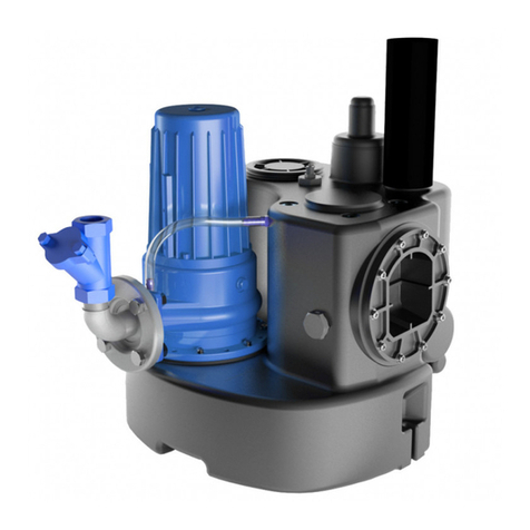
SFA
SFA SANICUBIC GR Series User manual

SFA
SFA SANIFOS 110 User manual
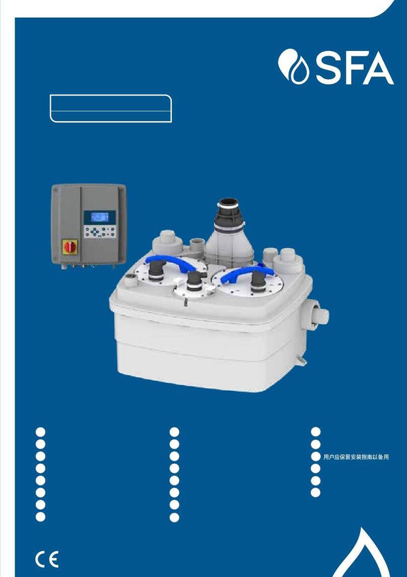
SFA
SFA SANICUBIC 2 PRO User manual

SFA
SFA SANIFOS 1600 User manual
SFA
SFA Sanifloor+ Manual

SFA
SFA SANICUBIC 1 User manual
SFA
SFA SANIACCESS3 User manual
SFA
SFA SANICUBIC 1 User manual

SFA
SFA SFA SANISPEED User manual
SFA
SFA SANIPUMP ZFS 71 Series Manual
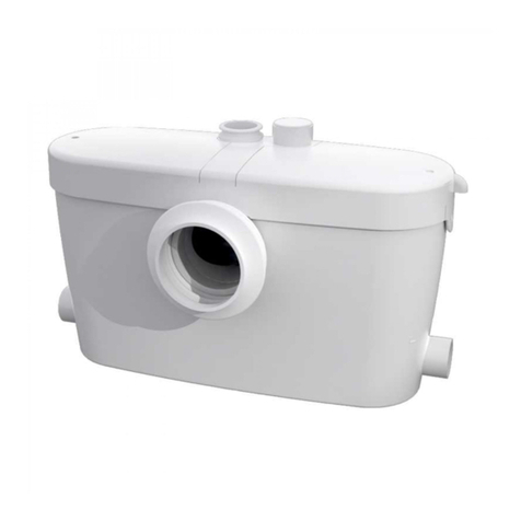
SFA
SFA SaniAccess 3 User manual
SFA
SFA SANICONDENS PRO Manual
SFA
SFA SANISUB S ZPK Series Manual
SFA
SFA SANIPUMP ZPG 71 Manual

SFA
SFA SANICUBIC 1 User manual
SFA
SFA SANIBROYEUR Silence SANI 1 User manual

SFA
SFA SANIVITE Instruction manual
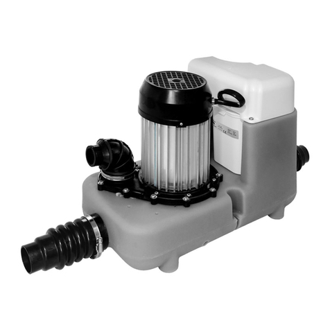
SFA
SFA SANICOM 1 Manual

SFA
SFA SANICOM 2 User manual

SFA
SFA SANICOM 1 Manual
