SGM P-1 User manual
USER
MANUAL
P-1P-1

2
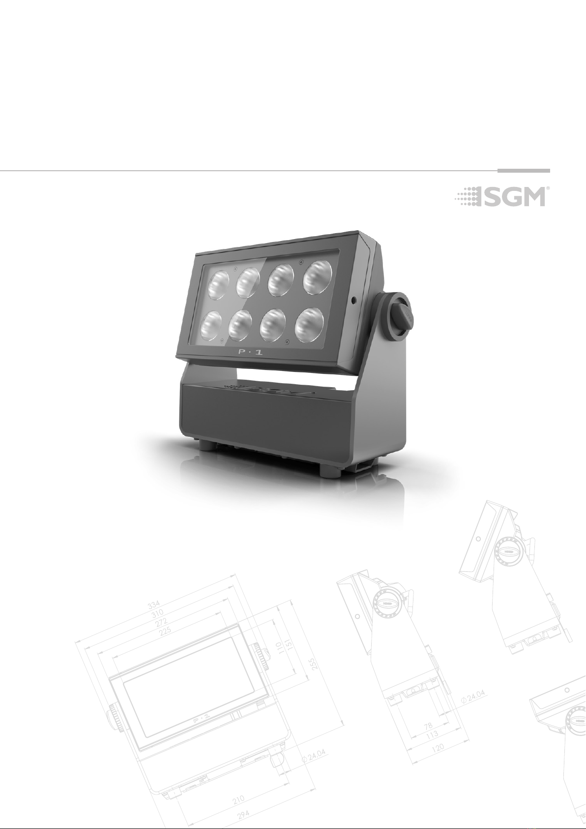
P-1 Dimensions
All dimensions in millimeters and inches. Drawing not to scale.
This manual covers installation, use, and maintenance of the SGM P-1.
P-1
USER MANUAL REV. C
© 2021 SGMTM. The information in this document is subject to change without notice. SGM and all aliated
companies disclaim liability for any injury, damage, direct or indirect loss, consequential or economic loss, or
any other loss occurred by the use of, inability to use, or reliance on the information contained in this manual.
The SGM logo, the SGM name, and all other trademarks in this document pertaining to SGM services or SGM
products are trademarks owned or licensed by SGM, its aliates and subsidiaries.
This edition applies to rmware version 2.00 or later.
English edition

3
Contents
P-1 Dimensions....................................................................................................................................................................................2
Safety information...............................................................................................................................................................................4
Overview...............................................................................................................................................................................................6
Parts identication and terminology .................................................................................................................................................6
Preparing for installation....................................................................................................................................................................7
Unpacking................................................................................................................................................................................................................7
Location / application ...............................................................................................................................................................................................7
Transportation..........................................................................................................................................................................................................7
Installing / rigging the P-1...................................................................................................................................................................7
Rigging process .......................................................................................................................................................................................................8
Ceiliing / Wall mount ................................................................................................................................................................................................9
Connecting AC power .........................................................................................................................................................................9
AC Power, battery and charging ......................................................................................................................................................10
AC Power loss function..........................................................................................................................................................................................10
Battery charging and use.......................................................................................................................................................................................10
Battery time and battery extension ........................................................................................................................................................................10
Conguring the device......................................................................................................................................................................10
Using the display panel ........................................................................................................................................................................................10
Display................................................................................................................................................................................................11
Wireless signal strength......................................................................................................................................................................................... 11
Current input type .................................................................................................................................................................................................. 11
Current DMX address ............................................................................................................................................................................................ 11
Current power source / battery level ..................................................................................................................................................................... 11
Error Indicator ....................................................................................................................................................................................................... 11
Shortcuts ............................................................................................................................................................................................................... 11
Connecting to a DMX control device...............................................................................................................................................11
Connecting a wireless transmitter.......................................................................................................................................................................... 11
Disconnecting a wireless transmitter .....................................................................................................................................................................12
Signal priority .........................................................................................................................................................................................................12
Conguring the device for DMX control..........................................................................................................................................12
About DMX ............................................................................................................................................................................................................12
DMX start address ................................................................................................................................................................................................12
Set/edit DMX address............................................................................................................................................................................................12
DMX modes ...........................................................................................................................................................................................................13
Using standalone operation .............................................................................................................................................................13
Setting a static color manually ........................................................................................................................................................13
Fixture properties..............................................................................................................................................................................13
Factory default ......................................................................................................................................................................................................13
Eects ....................................................................................................................................................................................................................13
Control menu .....................................................................................................................................................................................14
Individual xture settings ......................................................................................................................................................................................14
RDM ....................................................................................................................................................................................................16
Supported RDM functions......................................................................................................................................................................................16
RDM functions .......................................................................................................................................................................................................16
Sensors..................................................................................................................................................................................................................16
Accessories .......................................................................................................................................................................................17
Filter frames ..........................................................................................................................................................................................................17
Barndoors .............................................................................................................................................................................................................17
Maintenance /Service........................................................................................................................................................................18
Upgrading the rmware .........................................................................................................................................................................................18
Cleaning.................................................................................................................................................................................................................18
Troubleshooting ................................................................................................................................................................................18
Fixtures and accessories..................................................................................................................................................................19
Ordering information ..............................................................................................................................................................................................19
P-1 Accessories .....................................................................................................................................................................................................19
Support hotline..................................................................................................................................................................................19
Approvals and certications ............................................................................................................................................................19

4
Safety information
• Always power o/unplug the luminaire before removing covers or dismantling the product.
• Ensure that the mains power is cut o when wiring the device to the AC mains supply.
• Ensure that the device is electrically connected to earth (ground).
• Do not apply power if the device or mains cable is in any way damaged.
• Do not immerse the luminaire in water or liquid.
DANGER! Risk of electric shock. Do not open the device.
• Install in a location that prevents accidental contact with the device.
• Install only in a well-ventilated space.
• Install at least 0.3 m (12 in.) away from objects to be illuminated.
• Install only in accordance with applicable building codes.
• Ensure a minimum clearance of 0.3 m (12 in.) around the cooling fans.
• Do not paint, cover, or modify the device, and do not lter or mask the light.
• Keep all ammable materials well away from the device.
• Allow the device to cool for 15 minutes after operation before touching it.
Important note:
In order to preserve battery lifespan make sure the unit is fully charged before storage.
If stored for long periods of time, the batteries will need to be recharged every 3 months.
CAUTION: Exterior surface temperature after 5 min. operation = 38 °C (100 °F). Steady state = 68 °C (154 °F).
WARNING! Take measures to prevent burns and re.
• Do not look directly at the light source from close range.
• Take precautions when working at height to prevent injury due to falls.
• For Permanent Outdoor Installations (POI), ensure that the xture is securely fastened to a load-bearing surface with suitable
corrosion-resistant hardware.
• For a temporary installation with clamps, ensure that the quarter-turn fasteners are turned fully and secured with a suitable
safety cable.
• For elevated installations, secure the xture with suitable safety cables, and always comply with relevant load dimensioning,
safety standards, and requirements.
• The standard safety wire cable must be approved for a safe working load (SWL) of 10 times the weight of the xture, and
it must have a minimum gauge of 4 mm.
WARNING! Take measures to prevent personal injury.
WARNING!
Read the following safety precautions carefully before unpacking, installing,
powering, or operating the device.
SGM luminaires are intended for professional use only. They are not suitable for household use.
Les luminaires SGM sont impropre à l’usage domestique. Uniquement à usage professionnel.
This product must be installed in accordance with the applicable installation code by a person familiar with
the construction and operation of the product and the hazards involved.
Ce produit doit être installé selon le code d’installation pertinent, par une personne qui connaît bien
le produit et son fonctionnement ainsi que les risques inhérent.

5
Misusing the battery may cause the battery to get hot, rupture, or ignite, and cause serious injury. Make sure to follow
the safety informations listed below:
• Do not put the battery in re, attempt to heat it, or use it in a high temperature environment.
• Do not install the battery backwards with reversed polarity.
• Do not connect the positive terminal to the negative terminal of the battery with any metal object (such as a wire).
• Do not carry or store the battery together with necklaces, hairpins, or other metal objects.
• Do not pierce the battery with nails, strike the battery with a hammer, step on the battery, or otherwise subject it to strong
impacts or shocks.
• Do not expose the battery to water or salt water, or allow the battery to get wet.
• Do not disassemble or modify the battery. The battery contains safety and protection devices, which, if damaged, may
cause the battery to generate heat, rupture or ignite.
• Do not place the battery on or near res, stoves, or other high-temperature locations. Do not place the battery in direct
sunlight. Doing so may cause the battery to generate heat, rupture, or ignite. Using the battery in this manner may also
result in a loss of performance and a shortened life expectancy.
• Do not place the battery in microwave ovens, high-pressure containers, or on induction cookware.
• Immediately discontinue use of the battery if, while using, charging, or storing, the battery emits an unusual smell, feels hot,
changes color or shape, or appears abnormal in any other way.
• Only charge the battery mounted in the xture with the built-in charger. Do not use a third party charger.
• Do not charge unattended.
• Only charge the battery if the surrounding temperature is in the range of +7 to +35°C (45° to 95°F). Charging the battery
outside of this temperature range may cause the battery to heat up or break. It may also harm the performance of the bat-
tery or reduce the battery’s life expectancy.
• Do not replace the battery in the xture with other types of rechargeable batteries.
• Do not replace the battery in the xture with non-rechargeable batteries, such as dry-cell batteries etc.
• When the battery is worn out, insulate the terminals with adhesive tape or similar materials before disposal.
• Follow applicable laws and regulations for transport, shipping, and disposal of batteries. For details on recycling lithium,
lithium-phosphate, and lithium-ion batteries, please contact a government recycling agency or your waste-disposal service.
This warning applies to all SGM battery-driven products, due to the inside LI-ION battery.
WARNING! LI-ION Battery.
6
The P-1 is a battery-driven RGBW LED wash light with a small footprint and high output, designed for multiple applications, including
applications where wireless operation is essential.
P-1 features:
• A wash light, a strobe light, and pixel light, weighing only 5.7 kg/12.9 lbs.
• Multi-environmental luminaire due to its IP65-rating that can operate in many environments and in temperatures from
-20 °C to 50 °C.
• 8 high-power RGBW LEDs divided into two vertical, individually controllable LED segments.
• Fully adjustable color temperature correction (CTC) from 2,000 K to 10,000 K.
• Dierent beam angles available by using optional set of four magnetic easy-t holographic lter frames (19°, 45°, 63°x12°
elliptical, 12°x63° elliptical).
• Built-in wireless DMX and programmable standalone programs.
• Fully RDM compliant.
• Very low power consumption.
• Rubber feet meant for delicate surfaces, and prevents xture from sliding.
The xture also oers running for up to 12 hours in standard operation mode, the P-1 can easily be congured to provide an even
output over longer periods of time. The combination of wireless DMX and being battery powered, makes the P-1 extremely versatile
and able to serve a vast variety of creative purposes.
Overview
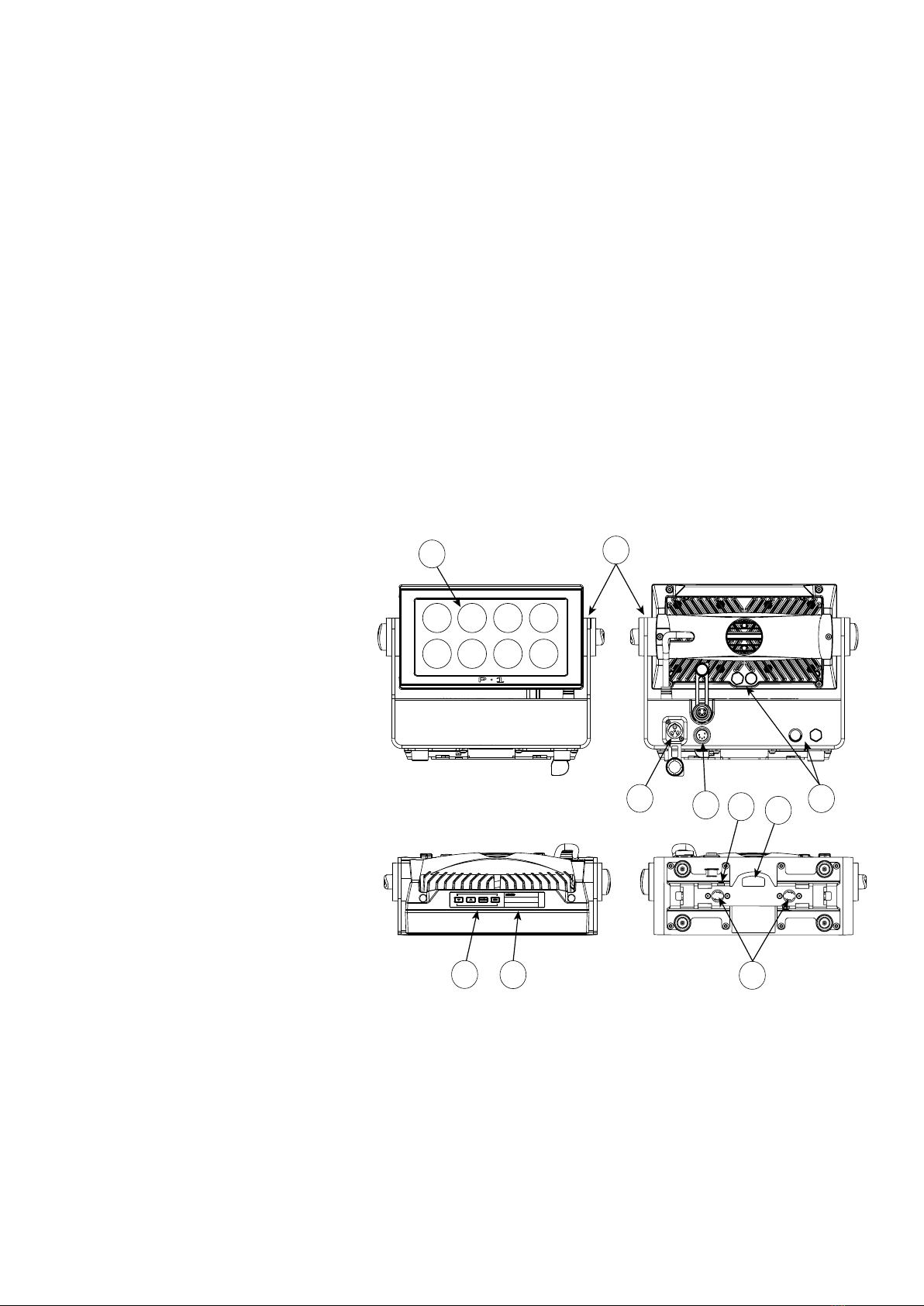
I
C
J
H
G
A: 8 x RGBW LEDs
B: Tilt lock
C: Power in
D: DMX in and out
E: Kensington lock socket
F: Safety wire attachment point
G: Dehumidifiers and GORE-TEX membranes
H: Control panel
I: OLED Display
J: Holes for Omega bracket
A
DF
E
B
Parts identication and terminology
Figure 1: Parts identication and terminology
7
Unpacking
Unpack the device and inspect it to ensure that it has not been damaged during transport.
The P-1 is shipped with:
• One IP66 power input connector, 2 m (78 in)
• One Omega bracket with 1/4-turn fasteners
• Filters (optional)
• Ceiling / wall mount (optional)
• Barndoor (optional)
Location / application
The xture is IP65-rated and designed for both indoor and outdoor events. This means that it is protected from:
• Dust, to the degree that dust cannot enter the device in sucient quantities as to interfere with its operation.
• Lower pressure jets of water from any direction.
When selecting a location for the device, ensure that:
• It is situated away from public thoroughfares and protected from contact with people.
• It is not immersed in water or exposed to high-pressure water jets.
• It has adequate ventilation.
Transportation
Always use the supplied packaging or suitable ight case for transportation and storage.
Never carry the xture by connected cables or wires.
Preparing for installation
The P-1 may be installed in any orientation. Always use an omega bracket to rig the xture and lock the bracket with the 1/4-turn
fasteners.
Please note:
The 1/4-turn fasteners are only locked when turned fully clockwise.
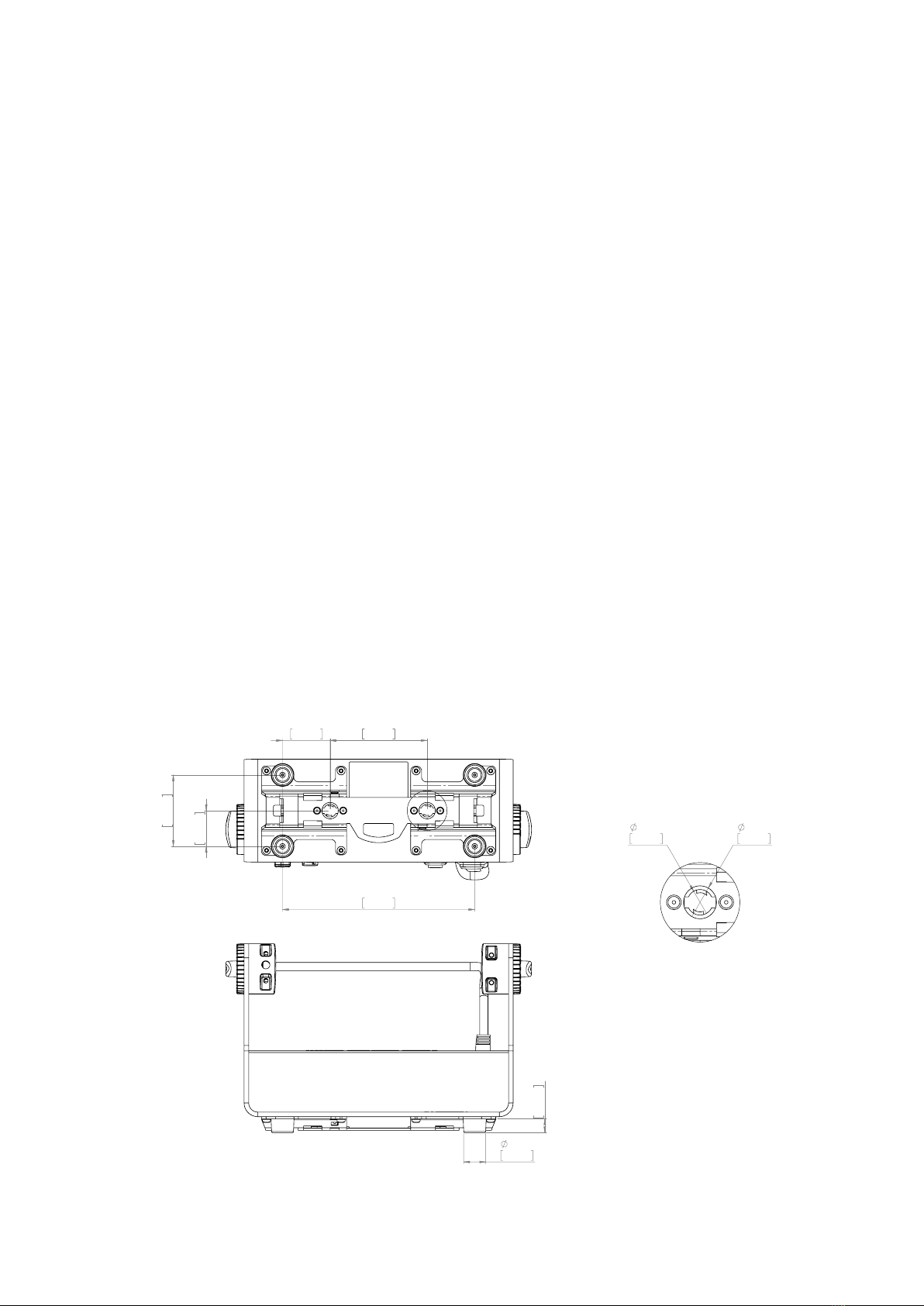
Installing / rigging the P-1
Figure 2: Dimensions for P-1 base locking points
24mm
0,946in
15mm
0,591in
106mm
4,173in
78mm
3,071in
210mm
8,268in
52mm
2,047in
39mm
1,535in
A
18mm
0,709in
14mm
0,551in
DETAIL A
SCALE 1 : 1
8
Rigging process
Start the rigging process by clearing the working area below, and make sure the work is performed from a stable platform.
1. Check that the clamp is undamaged and can bear at least 10 times the weight of the xture. Check that the structure can
bear at least 10 times the weight of all installed xtures, lamps, cables etc.
2. Bolt the clamp securely to the omega bracket with a M12 ½ bolt (min. grade 8.8) and a lock nut.
3. Align the omega bracket with the two 1/4 turn sockets in the base. Insert the fasteners into the base bracket, and turn both
levers a full1/4-turn clock wise to lock.
4. Working from a stable platform, hang the xture on a truss or other structure. Tighten the clamp.
5. Install a safety wire that can bear at least 10 times the weight of the xture. The safety wire attachment point is designed to
t a carabiner.
6. Verify that there are no combustible materials, cables, or surfaces to be illuminated within 0.3 m (12 in) of the xture.
7. Check that there is no risk of the head/yoke colliding with other xtures or structures.
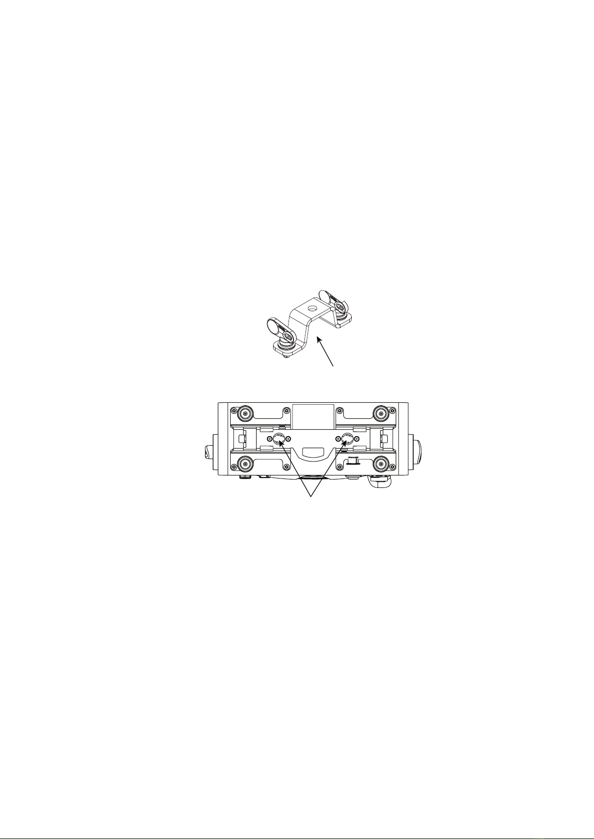
Holes for omega bracket
Omega bracket
Figure 3: Base with omega bracket

9
133mm
68mm
200mm
98mm
14,70mm
100mm
30mm
11,50mm
18,50mm
37mm
17mm
13mm
6mm
Lock
Unlock
Slide locks
Holes for
mounting
Holes for
mounting
Lock
screw
133mm
68mm
200mm
98mm
14,70mm
100mm
30mm
11,50mm
18,50mm
37mm
17mm
13mm
6mm
Lock
Unlock
Slide locks
Holes for
mounting
Holes for
mounting
Lock
screw
WARNING! Always secure an elevated P-1 with a safety wire.
Fasten a safety wire (not shown) between the load-bearing support structure and the safety wire attachment point on the device.
The safety cable (not included in the package) must:
• Bear at least 10 times the weight of the device (SWL).
• Have a minimum gauge of 4 mm.
• Have a maximum length (free fall) = 30 cm (12 in.).
CAUTION!
• Always use a safety wire of a grade AISI 316 steel.
• Make sure the slack of the safety wire is at a minimum.
• Never use the yoke for secondary attachment.
Ceiliing / Wall mount
The P-1 can be installed with an optional ceiling / wall mount. The ceiling / wall mount is design to t the base bracket on the P-1.
To install the ceiling / wall mount:
1. Loosen the lock screw on the ceiling / wall mount.
2. Install the ceiling / wall mount to the surface.
3. Position the xture over the four slide locks and slide to the locked position.
4. Fasten the lock screw.
Safety wire attachment point
Figure 4: Safety wire attachment point
Connecting AC power
The P-1 can operate on any 100-240 V, 50/60 Hz AC mains power supply.
Connect the xture to AC power using the supplied 8 mm cable (see gure 6) with a power connector or similar, with a maximum of
20 A, to ensure the correct ingress protection (IP rating). The P-1 can also run on battery power, up to 12 hours with the possibility to
extend the battery time up to 24 hours.
The fixture must be grounded/earthed and able to be isolated from AC power. The AC power supply must incorporate a fuse or
circuit breaker for fault protection.
For a temporary outdoor installation, the mains cable must be fitted with a grounded connector intended for exterior use.
For permanent installation, have a qualified electrician wire the mains cable directly to a suitable branch circuit. The ingress
protection (IP) rating of the TRUE1 connector and junction’s must be suitable for the location.
After connecting the P-1 to power, run the on-board test by selecting TEST → AUTOMATED TEST in the menu to ensure that the
xture and each LED are functioning correctly. Please see “Control menu” on page 14.
CAUTION!
Do not open the fixture to replace the supplied power cable.
Do not connect the fixture to an electrical dimmer system, as doing so may cause damage.
PLEASE NOTE:
The protective caps must be securely mounted on any unused DMX or power connector, in order to maintain the IP65-rating.
The fixture must be grounded/
earthed and be able to be isolated
from AC power. The AC power
supply must incorporate a fuse or
curcuit breaker for fault protection.
Color
Black
White
green/yellow
Conductor
live
neutral
ground (earth)
Symbol
or
L
N
Wire
Figure 6: Connecting AC Power/P-1 power cable 8 mm
Figure 5: P-1 Ceilling / Wall mount

10
AC Power loss function
By default the P-1 is set by default to continue on battery power when AC power is disconnected.
This can be congured in the settings of the P-1 menu, by selecting one of the following options:
• Battery backup - The xture continues on battery power if AC power is disconnected.
• Emergency light - The xture continues on battery power, with static white light at full output if AC power is disconnected.
• Power o - The xture turns o if AC power is disconnected.
Normal operation will resume when AC power is re-established to the P-1.
Battery charging and use
The batteries are charging when the P-1 is connected to AC power and:
• When the P-1 is o
• When the P-1 is on, but idle / not in use
The batteries do not charge while the xture is in active use, e.g. when the light source is on.
Charging from a discharged state to full voltage and: 70% of full capacity, 3.5 hours*, 100% of full capacity, 6.5 hours*.
After >1000 full cycles the expected battery capacity will be 85%* of the initial capacity. (Full cycle = 0% to 100% to 0%).
If the batteries are not fully charged/discharged, the number of cycles are higher.
PLEASE NOTE
Only use the P-1 connected to AC power when ambient temperatures are between 0°C and 45°C.
Running on battery power, the P-1 can be used when the ambient temperatures are between -20°C and 50°C.
Only charge the P-1 connected to AC power when ambient temperatures are between 7°C and 45°C.
Battery time and battery extension
When using the P-1 running on battery power the estimated battery capacity is up to 12 hours. The P-1 can be congured to extend
the battery time, for up to 24 hours by dimming the output accordingly. Go to MENU → SETTINGS → BATTERY EXTENSION.
The battery extension time set in the menu, only applies to a xture with fully charged batteries.
The battery time is reduced when using the P-1 in cold environments.
* Under the manufacturer’s test conditions.
AC Power, battery and charging
Conguring the device
The P-1 can be set up by using the control panel and OLED multi-line display at the top of the xture’s head or through RDM.
The OLED display is the human interface of the xture, as it displays the current status and menu of the xture. The display panel
can be used to congure individual xture settings, check the xture’s wireless status, conrm the rmware version, and read error
messages. The complete list of the menu and all commands available are listed in “Control menu” on page 14.
When the xture is powered on, it displays the currently selected operating mode and the DMX start address. Navigate through the
menus and options using the arrow buttons, and select items using the ENTER button.
Using the display panel
• Press the ‘ENTER’ button to access the menu or make a selection.
• Press the arrow buttons to scroll up and down in the menus.
• Press the ‘ESC’ button to take a step back in the menu.
• To turn o the P-1, press and hold the ‘ESC’ button until the xture turns o, or go to MENU → POWER OFF.
• To turn on the P-1, press any button and the xture will power on.
DMX
101
(113)
ESC ENTER
Figure 7: OLED display and control panel

11
The P-1 is controllable using a DMX control device, and it can be connected using either a DMX cable or via the xture’s
built-in LumenRadio CRMX wireless receiver system.
If using a cabled DMX system, connect the DMX IN cable to the input connector and DMX OUT cable to the output. Both connectors
are located on the rear of the xture’s base (chassis mounted male 5-pin XLR connectors). Terminate the DMX out cable of the last
xture in the data link.
For outdoor events, use at least IP65-rated XLR connectors.
Connecting a wireless transmitter
The P-1 is designed to look for wireless transmitters in ‘connect’ state, when this option is not yet enabled.
To connect the P-1 to a wireless transmitter:
• Log o the currently paired wireless transmitter - see “Disconnecting a wireless transmitter” on page 12”.
• Press the connect button on the wireless transmitter.
• Conrm that the xture has paired with the wireless transmitter.
Connecting to a DMX control device
Display
Wireless signal strength
Displays the signal strength of the wireless CRMX connection. The wireless signal strength symbol will be ashing if the paired trans-
mitter is out of range. If no transmitter is paired the symbol will be o.
Current input type
• When ‘DMX’ is displayed: The xture responds to data received through cabled DMX.
• When ‘CRMX’ is displayed: The xture responds to data received through wireless DMX.
Current DMX address
Displays the current DMX address. The DMX address is altered directly from this view. The next available DMX address is displayed
to the right. The DMX address will ash on no data input.
Current power source / battery level
Displays the current power source, indicated by a power cable symbol or a battery symbol.
Displays the current battery level.
Error Indicator
If any errors are detected, the message ‘ERR’ will be ashing in the display for easy detection.
To read the error message, select ENTER → INFO → ERRORS in the menu.
Shortcuts
• ESC + ENTER: Press ENTER to conrm factory defaults.
• ESC + UP: Press ENTER to start LED test.
• ESC + DOWN: Press ENTER to unpair CRMX.
• UP + DOWN arrows simultaneously = ip the display upside-down.
Figure 8: Display view
(113)
DMX
DMX
101
10
(113)
1
DMX
ERR
(113)
Next available
DMX address
Current
Battery level
Wireless
signal strength
Current
input type
Running on
AC power
Current
DMX address
If any errors are detected ‘ERR’ will be ashing
in the display for easy detection.
101
DMX
(113)

12
Disconnecting a wireless transmitter
To disconnect the xture from the currently paired wireless transmitter, go to SETTINGS → WIRELESS DMX → LOG OFF in the
menu.
Signal priority
The P-1 can be paired to an active wireless transmitter while is it connected to a DMX cable. The xture will prioritize cabled DMX
over wireless DMX.
The active input type is displayed under the wireless signal strength indicator. The signal strength can also be checked via RDM data
by using a external RDM device (e.g. the SGM A-4).
About DMX
The P-1 can be controlled using signals sent by a DMX controller on a number of DMX channels. DMX is the USITT DMX512-A
standard, based on the RS-485 standard. The signal is sent as DMX data from a console or a controller, to the xture(s) via a shielded
twisted pair cable designed for RS-485 devices.
PLEASE NOTE:
• Standard microphone cable is not suitable for transmitting DMX.
• Up to 32 fixtures can be linked to the same DMX chain. Additional fixtures will overload the link.
DMX start address
The P-1 can be operated in different DMX modes. For any of the modes, the first channel used to receive data from a DMX controller
is known as the DMX start address. For independent control, each P-1 must be assigned its own address. If two fixtures of the
same type have the same DMX address, they will behave identically. Address sharing can be useful for diagnostic purposes and
symmetrical control.
For independent control, each P-1 must be assign its own address have a DMX start address set. For example, if the first P-1 is set
to 3ch DMX mode with a DMX address of 10, it uses the channels 10, 11 and 12. Then the following P-1 in the DMX chain should be
set to a DMX address of 13. As the first fixture uses the prior 3 DMX channels, including channel 12, the next available channel is 13
(10+3=13 >> 13).
If two or more fixtures of the same type have the same DMX address, they will mimic each other’s behaviour. Incorrect settings will
result in unpredictable responses from the lighting controller. Address sharing can be useful for diagnostic purposes and symmetrical
control.
NOTE!
When using power link connection, make sure the maximum power capacity is not exceeded in order to avoid short-
circuit and damaging of the fixture.
Set/edit DMX address
The DMX address is shown on the OLED display in the control panel.
To change the address setting, press the up and down arrows. When the desired address is displayed, press ENTER to save the
setting.
For your convenience, the next available DMX address is displayed to the right.
See instructions on how to use the display panel in “Conguring the device” on page 10.
The P-1 also oers the option to set the DMX address through RDM.
Conguring the device for DMX control
13
DMX modes
The P-1 operates in dierent DMX modes. All detailed DMX charts are available at www.sgmlight.com under the respective products,
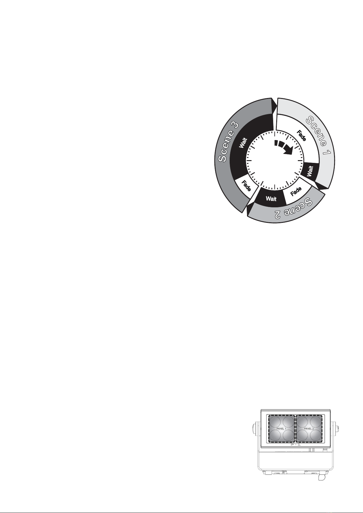
Standalone operation can be used when the xture is not connected to a control device. It can be programmed with a series of up
to 24 scenes, playing continuously in a loop. Up to three stand-alone programs can be dened and run from the menus, and one of
the programs can be set to run by default whenever the xture is powered on.
Each of the three available stand-alone programs contains 24 user-denable
scenes with its own RGB and shutter settings.
Each scene has a denable fade-in time for the transition from one color to the
next, and a wait (static) time of up to 120 minutes and 59 seconds.
To record a stand-alone program, press ENTER → MANUAL → EDITOR.
The standalone mode of the xture’s startup is enabled by pressing:
ENTER → SETTINGS → STARTUP MODE → SELECT STARTUP MODE →
STANDALONE.
To select the xture’s startup program, go to:
ENTER → SETTINGS → STARTUP MODE → STARTUP PROGRAM.
The chosen program will run its length cyclically whenever the xture is
powered on.
To run an internal program, go to:
ENTER → MANUAL → RUN PROGRAM.
To stop an active internal program, go to:
ENTER → MANUAL → STOP PROGRAM.
Using standalone operation
Figure 8: Standalone operation
Setting a static color manually
The P-1 can be congured to display a predened static color or color preset.
To set up a static color based on RGBW mixing, select ENTER → MANUAL → QUICK COLOR.
Note that once the MANUAL → QUICK COLOR settings are changed, the xture will, by default, be set to automatically start in quick
color mode whenever it is powered on. This can be reset through the menu SETTINGS → STARTUP MODE → SELECT STARTUP
MODE.
Since rmware version 2.22, the P-1 includes a number of color presets accessible via display. To set up a color preset, select:
ENTER → MANUAL → COLOR PRESETS
The current quick color program or selected color presset can always be stopped by selecting:
ENTER → MANUAL → STOP PROGRAM
See “Control menu” on page 14 for detailed information.
Factory default
When restoring factory defaults in the P-1, the following will be set:
• DMX address = 1
• DMX mode = Default mode (6 channel)
• Startup mode = DMX
• Flip screen = O
• Power loss function = Battery backup
• RDM device label set to = Fixture type name
• Internal program reset
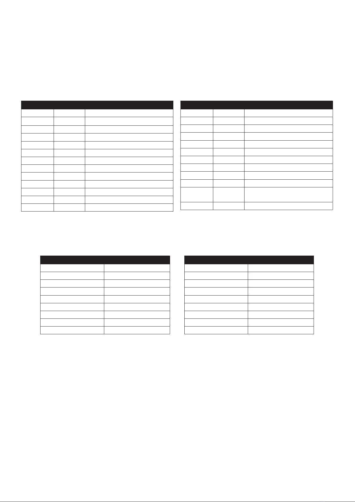
Eects
Colors and LED Panels
The P-1 features 8 high-power 12.5W RGBW LEDs, divided in two individually controllable
panels (left and right). Each panel represents a cluster of four lenses.
The xture can operate in RGB calibrated mode which ensures that colors are compatible
Fixture properties
Figure 9: P-1 Pixel segments

14
Control menu
Level 1 Level 2 Level 3 Level 4 Function
Mode Select mode - - Select DMX mode.
Manual Quick color Red 0-255 Static quick color - red mix (0-255). Sets xture to quick
color startup mode.
Green 0-255 Static quick color - green mix (0-255). Sets xture to quick
color startup mode.
Blue 0-255 Static quick color - blue mix (0-255). Sets xture to quick
color startup mode.
White 0-255 Static quick color - white mix (0-255). Sets xture to quick
color startup mode.
Full color calib. On or o Select between color calibrated or RAW color mode.
Color preset Intensity 0-255 Dimmer.
Color White 3200 K Color preset #
White 5600 K
White 10000 K
Congo
Red
Green
Blue
Orange
Light green
Pink
Light blue
Purple
Neon green
Magenta
Cyan
Yellow
CTC
Run program 1, 2 or 3 - Runs internal sequence 1, 2 or 3.
Stop program - - Stops current running internal sequence or Quick Color.
Editor Program - Edits scenes.
across the range of SGM xtures. However, the P-1 also oers the ability to operate in RAW mode with full control of each color.
Color temperature correction
The P-1 oers seamless CTC (color temperature correction) control from 2000° Kelvin - 10000° Kelvin. The color temperature can
also be modied via color presets when in manual operation (see above).
Beam angle
The P-1 is equipped with a xed 10° beam angle. The beam angle can be manipulated in various ways by using one of the optional
magnetic holographic lters (19°, 45°, 63°/12° elliptical), and 4/8 way barndoors.
Individual xture settings
Flipping the display
If the xture is installed hanging upside down, it may be useful to ip the display so that it is easier to read.
To ip the display, press ENTER and select SETTINGS → FLIP DISPLAY, or press the up and down buttons on the control panel at
the same time.
Setting the OLED display saver
By default the OLED display dims down after a short period when the control panel is in the root menu and not in use. The display can
also be set to turn o completely, ideal when a pitch-black environment is required. Pressing any key will always turn on the display
or restore it to normal brightness.
To congure the display settings, press ENTER → SETTINGS.
NOTE: To avoid the risk of display deterioration caused by long term use, it is recommended to select the setting → DISPLAY OFF.

15
Level 1 Level 2 Level 3 Level 4 Function
Info Product type - - Displays product type.
Firmware version - - Displays installed rmware version.
Serial number - - Displays SGM serial#.
DRM ID - - Displays RDM ID. (Unique RDM ID for identication).
DMX view Up to 492 DMX addresses - Displays received DMX levels.
Sensors Mainboard - Displays xture temperatures.
Led left -
Led right -
Humidity - Displays humidity percentage.
AC connected - Displays whether power is connected or not.
Battery PCT - Displays battery level.
Charging - Displays whether the battery is charging or not.
Battery VDC - Displays battery voltage.
Wireless signal - Displays wireless signal strength.
Wireless paired - Displays wireless connection status.
On time red 1 - Display LED total power on time. (R, G, B, W).
On time green 1 -
On time blue 1 -
On time white 1 -
On time red 2 -
On time green 2 -
On time blue 2 -
On time white 2 -
Power on time - - Displays xture total power on time.
LED on time - - Displays LED total power on time. (R, G, B, W).
Errors - - Displays error codes.
Settings Wireless DMX Log o -Sends Log o command to the CRMX System.
Enable/disable - Enable/disable wireless DMX functionality.
Bridge - Display strength of the wireless connection.
Status - Displays wireless connection status.
Startup mode Select startup mode - Default operating mode when xture is powered on:
1. DMX (factory default)
2. Stand-alone
3. Quick Color
Startup program Select startup
program
Stand-alone program 1, 2 or 3.
Only used if the startup mode is set to “stand-alone”.
Program 1 is default.
DMX loss DMX hold - Select what happens if DMX signal is lost.
All on -
Blackout -
Quick color -
AC power loss
function
Battery backup - Select what happens if AC power connection is lost.
Emergency light -
Power o -
Battery extension Set battery extension time O or 1-24h Congures battery extension function.
LED frequency Set LED frequency - Sets LED frequency.
Flip display - - Flips control panel display.
Display o - - Toggles automatic display sleep.
Factory default - - Reset the xture to factory default settings.
Service pin - - -
Service menu - - -
Test Self test Start/stop self test - Activates automated self test.
Display test - - Test the xture display.
Color test Start/stop color test - Test the LED segments of the xture.
Power o - - - Turns the xture o.
16
Supported RDM functions
The P-1 features support for various RDM functions, as per the ANSI E1.20 standard.
RDM (Remote Device Management) is a protocol enhancement to USITT DMX512 that allows bi-directional communication between
the xtures and the controller over a standard DMX line. This protocol will allow conguration, status monitoring, and management.
A RDM enabled controller is required to control the supported parameters. See the tables below for supported RDM functions.
RDM functions
RDM
Name Sensor Type
Mainboard Temp. Temperature
LED Left Temperature
LED Right Temperature
Humidity Other
AC power connected Contacts
Battery PCT (percentage) Other
Battery charging Contacts
Battery voltage Voltage
Wireless signal strength Other
Name Sensor Type
Wireless paired Other
Red LED Hours Pixel 1 Time
Green LED Hours Pixel 1 Time
Blue LED Hours Pixel 1 Time
White LED Hours Pixel 1 Time
Red LED Hours Pixel 2 Time
Green LED Hours Pixel 2 Time
Blue LED Hours Pixel 2 Time
White LED Hours Pixel 2 Time
PID Actions Name
0x00F0 GET / SET DMX Start Address
0x00E0 GET / SET DMX Personality / Mode
0x00E1 GET DMX Personality Description
0x1000 GET / SET Identify
0x1001 SET Reset Device
0x0200 GET Sensor Denition
0x0201 GET / SET Sensor Value
0x0082 GET / SET Device Label
0x0081 GET Manufacturer Label
0x8060 GET Serial Number
0x0080 GET Device Model Description
0x0400 GET / SET Device Hours
0x0051 GET Parameter Description
PID Actions Name
0x0501 GET / SET Display Level, 0=OFF, 1 and above=ON
0x0500 GET / SET Display Invert
0x8626 SET CRMX Log O
0x8631 GET / SET Battery Extension Hours
0x0090 SET Factory Defaults
0x0120 GET Slot Info
0x0121 GET Slot Description
0x0122 GET Default Slot Value
0x8637 GET / SET Bridge ENABLE=1 DISABLE=2
0x8620 GET / SET Led freq (197647Hz) / value
0x8634 GET / SET Quick color feature 0=HOLD 1=WHITE
2=OFF 3=Q COLOR
0x8636 GET Active Error
Please note: The RDM controller communicates with the xtures to show only the available options for each RDM function. The table is subject to change without notice.
Sensors
RDM enables various sensor readouts for remote device monitoring. See the table below for sensors and sensor types.
Please note: The RDM controller communicates with the xtures to show only the available sensors for this xture. The table is subject to change without notice.
17
Accessories
Barndoors
The P-1 features optional 4-way and 8-way barndoors. The barndoors are designed and intended to be mounted on the xture with-
out the use of any tools.
To install the barndoors:
1. Pull the two lock pins to the unlocked position and place the barndoor on the front of the P-1 head.
2. Release the lock pins and check the lock pins are correctly in place.
3. Attach a safety wire to the barndoor and secure it to the yoke on the P-1.
The barndoor can be mounted simultaneously with a lter frame.
The P-1 can be used with various accessories such as cables, barndoors, and lter frames.
To get to know all the available P-1 accessories, visit www.sgmlight.com or contact your local SGM dealer.
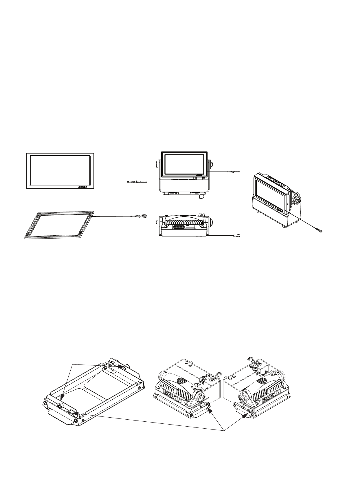
Filter frames
The P-1 features various optional, magnetic holographic lter frames:
• Medium angle (19°)
• Wide angle (45°)
• Elliptical wide angle horizontal (63°x12°)
• Elliptical wide angle vertical (12°x63°)
The lter frames install easily using magnets built-in to the frames and xtures. To install them, position the lter frame in front of the
light, and snap it into place.
The frames are tted with a safety wire to secure the frame to the yoke on the P-1.
A lter frame can be mounted simultaneously with a barndoor.
For further information and other possibilities visit www.sgmlight.com or contact your local SGM dealer.
Lock pins
Safety wire attachment points
Filter frame front view
Filter frame back view P-1 with lter frame
Figure 11: P-1 Barndoors
Figure 10: P-1 Filter frames

18
Upgrading the rmware
The rmware installed in the xture can be identied in dierent ways:
• When powering on the xture, the display shows the current installed rmware version
• Going to the MENU → INFO → FIRMWARE VERSION
• Through RDM
We recommend that the xture’s rmware is always up-to-date. The latest rmware version is available for download under the
respective product at www.sgmlight.com.
To update your P-1 with the latest rmware use an SGM USB 5-Pin-XLR uploader cable (available from your nearest SGM dealer)
and a Windows-based computer with the SGM Firmware Tool software installed (also available for download at www.sgmlight.com).
Additionally, the Firmware Tool software oers a simple DMX controller featuring 512 DMX channels for test purposes.
Cleaning
SGM luminaires with IP65-rating do not need cleaning inside the xture. However, cleaning the front lens may be needed to achieve
the maximum light output after exposure to dust, sand, or dirt. The exterior housing can also be cleaned to get a better look. To main-
tain adequate cooling, fans must be cleaned periodically.
Whenever necessary, clean the P-1 using a soft cloth dampened with a solution of water and a mild detergent. Do not use products
that contain solvents, abrasives, or caustic agents for cleaning, as they can cause damage to hardware, cables, and connectors.
The level of cleaning required will vary greatly depending on the operating environment and installation. Therefore, it is recommended
to do frequent check-ups the rst few weeks of operation to see how often cleaning is necessary.
Maintenance /Service
Figure 12: SGM Firmware tool
Troubleshooting
Problem Potential cause(s) Remedies
Fixture does not respond or
appears to be completely dead.
No power to the xture. Conrm that the power is switched on, conrm that the
cables are plugged in, and the TRUE1 connector is
inserted and turned to its locked position.
The batteries are discharged. Charge the batteries by connecting AC power.
The xture has been turned o. Press any button on the control panel to turn on the xture.
Fixture suddenly turned o. Power was turned o. Check the power supply, switches and breakers.
Fixture suddenly stopped
responding.
The wireless transmitter or connections, was disconnected/
tampered with.
Inspect the wireless transmitter and connections.
DMX cables were disconnected. Inspect DMX cables.
Fixture operates irregularly /
abnormal.
DMX cable polarization is inverted (pin 2 + 3). Install a polarity-inverter or replace cables.
DMX link is not terminated. Install a XLR 120ohm DMX termination at the end of
the DMX link.
Corrupted DMX cable. Replace or repair defective cables and/or connections.
The xture operates an internal program. Go to MENU → MANUAL → STOP PROGRAM
A corrupted xture generates noise/disruptions on the DMX link. Track and isolate the corrupted xture.
Color is uneven. The minimum values are out of calibration. Contact your local SGM dealer or [email protected]

19
Fixtures and accessories
The P-1 can be used with a variety of accessories.
Contact your local SGM dealer to get the latest pricing and news about available accessories.
Please note: the listed below are subject to change without notice.
Ordering information
P-1, Std, BL (incl. 3 pcs Batt)............................................................................................................................................. P/N: 80031501
P-1, Std, WH (incl. 3 pcs Batt)............................................................................................................................................ P/N: 80031511
P-1, Std, CU (incl. 3 pcs Batt)............................................................................................................................................ P/N: 80031521
P-1, Std, BL (excl. 3 pcs Batt)............................................................................................................................................ P/N: 80031502
P-1, Std, WH (excl. 3 pcs Batt).......................................................................................................................................... P/N: 80031512
P-1, Std, CU (excl. 3 pcs Batt)........................................................................................................................................... P/N: 80031522
P-1 Accessories
Power cable with IP connector........................................................................................................................................ P/N: 07860275
Omega bracket with quarter turn bolts, BL / WH.............................................................................................. P/N: 83060602 / 83061202
Battery, Nominal: 21,6V - Nominal: 3350 mAh (1 pcs)....................................................................................................... P/N: 83061709
Battery, Nominal: 21,6V - Nominal: 3350 mAh (2 pcs)....................................................................................................... P/N: 83061710
SGM USB uploader cable..................................................................................................................................................P/N: 83062011
P-1 Ceiling/Wall mount, BL /WH......................................................................................................................P/N: 83060614 / 83061214
Filter Frame - Medium Angle, BL / WH.............................................................................................................P/N: 83061140 / 83061240
Filter Frame - Wide Angle, BL / WH..................................................................................................................P/N: 83061141 / 83061241
Filter Frame - Elliptical Horz wide angle, BL / WH.............................................................................................P/N: 83061142 / 83061242
Filter frame - Elliptical Vert wide angle, BL / WH...............................................................................................P/N: 83061147 / 83061247
Barndoor 4-way, P-1 series, BL / WH...............................................................................................................P/N: 83061138 / 83061238
Barndoor 8-way, P-1 series, BL / WH.............................................................................................................P/N: 83061139 / 83061239
Flightcase for 4 pcs P-1..................................................................................................................................................... P/N: 82051009
Flightcase for 4 pcs P-1 incl. charger................................................................................................................................. P/N: 82051010
Flightcase Charger Cable Assembly Kit (4 pcs)................................................................................................................ P/N: 83062044
Vacuum test kit.................................................................................................................................................................P/N: 83061136
28 mm spigot adapter for omega bracket..........................................................................................................................P/N: 83060639
Support hotline
SGM oers 24/7 technical support hotline.
Worldwide: +45 3840 3840
US: +1 407-242-6217
Certied to CSA No. 166
Conforms to 73
Conforms to 2014/35/EU: Low Voltage Directive
Conforms to 2014/30/EU: EMC Directive
Conforms to 2011/65/EU: RoHS2 Directive
Approvals and certications
The information in this document is subject to chance without notice. For the latest information, visit www.sgmlight.com.

Other manuals for P-1
2
Table of contents
Other SGM Lighting Equipment manuals


SGM
SGM Giotto WASH 1200 User manual

SGM
SGM Giotto spot 400 User manual

SGM
SGM Pilot 2000 Operator's manual

SGM
SGM Q?7 User manual

SGM
SGM Q-8 User manual

SGM
SGM G-4 RGBAM WASH User manual

SGM
SGM PALCO 3 User manual

SGM
SGM Giotto spot 1200 User manual

SGM
SGM IDEA SCANNER 250 User manual

SGM
SGM Hazer 400 User manual


Popular Lighting Equipment manuals by other brands


Clevertronics
Clevertronics L10 CleverFit Exit LCFLED Series ASSEMBLY, INSTALLATION & MAINTENANCE INSTRUCTIONS

Lagler
Lagler 900.63.01.100 Operating Instructions / Safety Instructions

SloanLED
SloanLED PosterBOX Mini installation guide

avide
avide CLAUDE ABLDL-BLC manual

American DJ
American DJ FLASH PANEL 16 User instructions

B&G
B&G HERCULES Basic operation guide