SGM G-7 BEAST User manual

USERMANUAL
Product Version 1 | Manual Revision E | Released 2023-09-19
This manual covers installation, use, and maintenance of the SGM G-7 Beast. A digital version is available at www.
sgmlight.com or upon request via suppor[email protected]. The information in this document is subject to change
without notice. SGM and all affiliated companies disclaim liability for any injury, damage, direct or indirect loss, conse-
quential or economic loss, or any other loss occasioned by the use of, inability to use, or reliance on the information
contained in this manual. The SGM logo, the SGM name, and all other trademarks in this document pertaining to
SGM services or SGM products are trademarks owned or licensed by SGM, its affiliates, and subsidiaries. This edition
applies to firmware version 2.23 or later.
English edition © 2023 SGM Light A/S®.
G7 BEAST

2Product Version 1.0 | Revision E | Released 2023-09-19
G7 BEAST DIMENSIONS
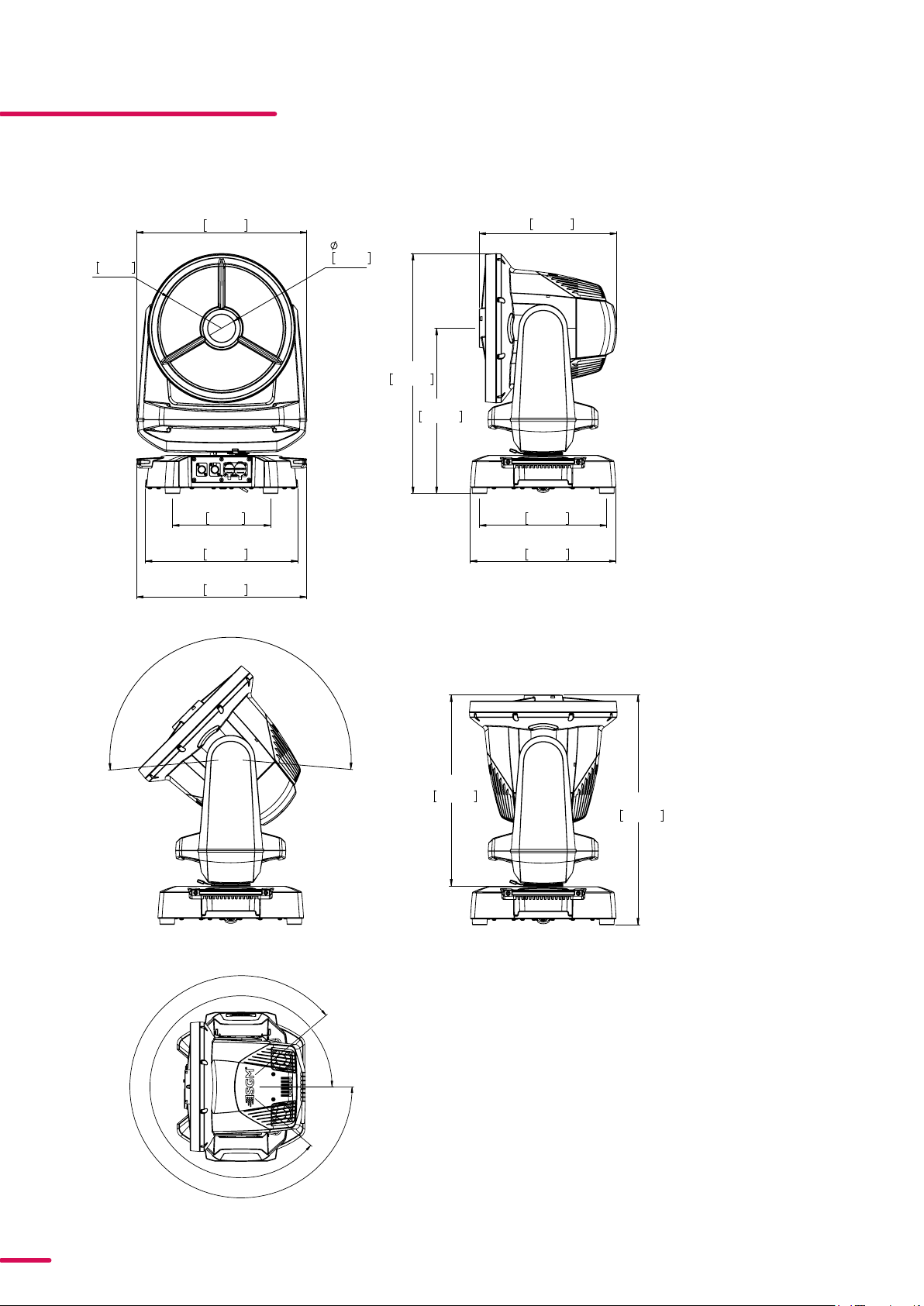
G7 BEAST STANDARD VERSION
323mm
12,72in
370mm
14,56in
416mm
16,37in
604mm
23,77in
349mm
13,75in
249mm
9,80in
432mm
17,01in
387mm
15,25in
R156mm
6,14in
70mm
2,75in
433mm
17,04in
185°
578mm
22,77in
480mm
18,91in
310°
310°
All dimensions in millimetres and inches. Drawing not to scale
323mm
12,72in
370mm
14,56in
416mm
16,37in
604mm
23,77in
349mm
13,75in
310°
310°
249mm
9,80in
432mm
17,01in
387mm
15,25in
R156mm
6,14in
70mm
2,75in
433mm
17,04in
185°
578mm
22,77in
480mm
18,91in

3Product Version 1.0 | Revision E | Released 2023-09-19
G7 BEAST POI VERSION
323mm
12,72in
370mm
14,56in
416mm
16,37in
604mm
23,77in
349mm
13,75in
249mm
9,80in
432mm
17,01in
387mm
15,25in
12,28in
70mm
2,75in
433mm
17,04in
312mm
70mm
1,46in
All dimensions in millimetres and inches. Drawing not to scale

4Product Version 1.0 | Revision E | Released 2023-09-19
CONTENT
2 G-7 BEAST DIMENSIONS
2 G-7 Beast Standard version
3 G-7 Beast POI version
7 SAFETY INFORMATION
8 BEFORE INSTALLING THIS PRODUCT
9 INSTALLATION STANDARD FIXTURE
9 Parts identication and terminology
10 Unpacking
10 Application considerations
10 Transport handling
10 Rigging
11 Rigging process using SGM Omega bracket
12 Power requirements
13 CONNECTING POWER
13 Connecting data
13 Wireless
13 Signal priority
14 INSTALLATION POI FIXTURE
14 Identication and terminology
15 Unpacking
15 Application considerations
15 Connecting temporary Power
15 Connecting temporary signal
16 Wireless Data Connection
16 Disconnecting a wireless transmitter in POI
16 LED Indicator
17 Settings and Fixture Defaults
18 Mounting
19 MECHANICAL TOLERANCES AND RECOMMENDED USE IN LOW AMBIENT
19 TEMPERATURES
20 Permanently Connecting Power & Data
21 USER INTERFACE
21 Wireless signal INDICATOR(A)
21 Fixture Name (B)
21 Next DMX Address (C)

5Product Version 1.0 | Revision E | Released 2023-09-19
CONTENT
21 DMX Start Address (D)
21 DMX Mode (E)
21 Using the keyboard (F)
21 Display settings
22 CONNECTING TO A DMX CONTROL DEVICE
22 Connecting to a DMX control device
22 Connecting a wireless transmitter
22 Disconnecting a wireless transmitter
22 Signal priority
23 About DMX
23 DMX Start address
23 Setting the DMX address
23 DMX modes
23 CONFIGURING THE DEVICE FOR DMX CONTROL
24 G-7 BeaSt Connection diagram
25 USING STAND-ALONE OPERATION
25 Manual control/ Internal sequence editor
25 Editor
26 CONTROL MENU
28 FACTORY DEFAULT
29 RDM
29 Supported RDM functions
29 RDM functions
29 Sensors
30 TROUBLESHOOTING
31 ERRORS
32 FIXTURE PROPERTIES
32 Motorized collimation
33 High-precision pan and tilt
33 Dual high-speed strobe eect
33 Color wheels position
35 OPENING THE FIXTURE
38 POLYTETRAFLUOROETHYLENE MEMBRANE
39 Module and lens warranty

6Product Version 1.0 | Revision E | Released 2023-09-19
40 MAINTENANCE
40 SGM Vacuum Test kit
41 Cleaning
41 Maintenance Schedule G-7
41 rmware updates
42 Maintenance Notes
42 Cleaning
42 Ordering information
42 G-7 BeaSt accessories
42 G-7 BeaSt Consumables
43 APPROVALS AND CERTIFICATIONS
43 SUPPORT HOTLINE
44 USER NOTES
CONTENT

7Product Version 1.0 | Revision E | Released 2023-09-19
SAFETY INFORMATION
SGM luminaires are intended for professional use only. They are not suitable for househovld use.
Les luminaires SGM sont impropre à l’usage domestique. Uniquement à usage professionnel.
This product must bew installed in accordance with the applicable installation code by a person
familiar with the construction and operation of the product and the hazards involved.
Ce produit doit être installé selon le code d’installation pertinent, par une personne qui connaît
bien le produit et son fonctionnement ainsi que les risques inhérent.
DANGER! RISK OF ELECTRIC SHOCK DO NOT OPEN THE DEVICE!
• Always power off/unplug the fixture before removing covers or dismantling the product.
• Ensure that the mains power is cut off when wiring the device to the AC mains supply.
• Ensure that the device is electrically connected to earth (ground).
• Do not apply power if the device or mains cable is in any way damaged.
• Do not immerse the fixture in water or liquid.
WARNING! TAKE MEASURES TO PREVENT BURNS AND FIRE!
• Install in a location that prevents accidental contact with the device.
• Install only in a well-ventilated space.
• Install at least 0.3 m (12 in.) away from objects to be illuminated.
• Install only in accordance with applicable building codes.
• Ensure a minimum clearance of 0.1 m (4 in.) around the cooling fans
• Do not paint, cover, or modify the device, and do not filter or mask the light.
• Keep all flammable materials well away from the device.
Allow the device to cool for 15 minutes after operation before touching it
CAUTION: Exterior surface temperature after 5 min. operation = 47 °C (117 °F). Steady state =
56 °C (133 °F).
WARNING! TAKE MEASURES TO PREVENT PERSONAL INJURY. DO NOT
LOOK DIRECTLY AT THE LIGHT SOURCE FROM CLOSE RANGE.
• Take precautions when working at height to prevent injury due to falls.
• For Permanent Outdoor Installations (POI), ensure that the fixture is securely fastened to
a load-bearing surface with suitable corrosion-resistant hardware.
• For a temporary installation with clamps, ensure that the quarter-turn fasteners are
turned fully and secured with a suitable safety cable. The standard safety wire cable must
be approved for a safe working load (SWL) of 10 times the weight of the fixture, made of a
grade AISI 316 steel, and it must have a minimum gauge of 3 mm.
• For elevated installations, secure the fixture with suitable safety cables, and always
comply with relevant load dimensioning, safety standards, and requirements.
WARNING! READ THE FOLLOWING SAFETY PRECAUTIONS CAREFULLY BE-
FORE UNPACKING, INSTALLING, POWERING OR OPERATING THE DEVICE.

8Product Version 1.0 | Revision E | Released 2023-09-19
BEFORE INSTALLING THIS PRODUCT
Please visit the SGM official website at www.sgmlight.com for the latest version of this user
manual/ safety information leaflet. Due to continuous improvements, the instructions may
change without notice. SGM always recommends the latest available firmware version from
www.sgmlight.com.
EXTERNAL CLEANING AND VISUAL INSPECTION OF THE FIXTURE
All users of the SGM fixtures should regularly clean those parts of the fixture directly exposed to
the elements, such as the external housing and front lenses. Additionally, all owners of the SGM
fixtures must periodically check the external housing of the fixture for structural breaks, deteri-
oration, cracked lenses, or loose screws. To ensure proper operation, but also to prevent the risk
of potential accidents, do not use the fixture if the lens, housing, or power cables are damaged.
If parts of the fixture appear to be missing, cease use immediately and contact SGM support.
WIRING AND CONDUIT/ CONTAINMENT
SGM fixtures supplied with power and data cable leads are not intended for installation in
permanently installed conduit or containment. When installing the fixtures in a permanent
installation, ensure cable leads are installed as a service loop to an appropriately rated junction
box using suitable cable strain reliefs/glands. All installed fixtures must be securely mounted,
and service loop appropriately protected for installation location. All electrical wiring and
connections should be completed by a qualified electrician.
SAFETY PRECAUTIONS
When using electrical equipment, basic safety precautions should always be followed including
the following:
• Do not mount near gas or electric heaters.
• Permanently installed equipment should be mounted in locations and at heights where
it will not be readily subjected to tampering by unauthorized personnel.
• The use of accessory equipment not recommended by the manufacturer may cause an
unsafe condition.
• Do not use this equipment for other than intended use.
• Refer service to qualified personnel or authorized service centers.
• Do not look directly into the beam for long periods of time, when the fixture is on.
• The fixture shall, under no circumstance, be covered with insulating material of any kind.
READ AND FOLLOW ALL SAFETY INSTRUCTIONS.

9Product Version 1.0 | Revision E | Released 2023-09-19
INSTALLATION STANDARD FIXTURE
The G-7 BeaSt/ G-7 BeaSt POI is a fast, lightweight and mid-sized Beam Strobe moving head with high-output and
low power consumption, designed for multiple applications, including when wireless operation is essential.
The G-7 BeaSt features:
An IP66 rated moving head with two separated white LED engines: a 6,500 K Beam and a 8,000 K Strobe Blinder*.
2 colour wheel with 18 colours, including CTO and open.
Motorized collimation from -1° to 30°.
Built-in wireless DMX.
Full RDM compatibility.
1 aerial gobo wheel with 6 rotatable gobos, including Frost + open.
Low power consumption.
Superior thermal management for high reliability.
*The light sources of the fixture are expected to run until about 20,000 hours LM-70/ TM-21.
PARTS IDENTIFICATION AND TERMINOLOGY
Figure 1: G-7 BeaSt parts and terminology
I
K
J
A
B
C
F
D
H
E
G
A: Front lens
B: DMX in and out
C: Power in and out
D: Tilt lock/unlock
E: Display and control panel (POI n/a)
F: Yoke handles
G: Pan lock/unlock
H: Base handle (x2)
I: Holes for omega bracket (x8)
J: Rubber feet (x4)
K: Safety wire attachment point

10 Product Version 1.0 | Revision E | Released 2023-09-19
UNPACKING
Unpack the device and inspect it to ensure that it has not been damaged during transport.
The G-7 BeaSt is shipped with:
• 2 m (78 in.) power cable with IP connector.
• Two omega brackets with 1/4-turn fasteners.
• Safety information leaflet.
APPLICATION CONSIDERATIONS
The fixture is IP66-rated and designed for both indoor and outdoor events. This means that it is protected from:
• Dust, to the degree that dust cannot enter the device in sufficient quantities, as to interfere with its opera-
tion.
• High pressure water jets from any direction.
When selecting a location for the device, ensure that:
• It is situated away from public thoroughfares and protected from contact with people.
• It is not immersed in water.
• It has adequate ventilation.
When using the fixture with a DMX controller, ensure that:
• According to RS485 standard, the DMX Out of the last fixture should be terminated with a 120 ohm resistor
between pin 2 and 3.
• If the resistor is not installed, make sure that the DMX Out is properly sealed by mounting the protection cap,
in accordance with the ingress protection (IP) requirements.
• A maximum of 32 fixtures can be connected to the same DMX link.
TRANSPORT HANDLING
• Always use the supplied packaging or suitable flight case for transportation and storage.
• Release the tilt lock when transporting the fixture. Leaving the tilt lock blocked may cause damage to the
fixture.
• Never carry the fixture by connected cables or wires, use the handles.
PLEASE NOTE.: THE 14TURN FASTENERS ARE ONLY LOCKED WHEN TURNED FULLY CLOCKWISE.
Depending on the structure, please use appropriate and secure methods for mounting the Omega bracket.
All SGM luminaries have locking points at the base for instal-
lation and rigging. The distance between the points from
centre to centre is always 106 mm (Fig. 2). The base of the
standard G-7 BeaSt includes 1/4-turn fastener cam locks to
mount the omega brackets. For further details of the bracket
dimensions contact SGM support.
The G-7 BeaSt may be installed in any orientation, with or
without base, on the ceiling or on a wall surface.
Always use the supplied omega brackets and lock with
1/4-turn fasteners (fig 3).
106 mm
[ 4,2in ]
Ø 18 mm
[ 0,7in ]
Figure 2: SGM Locking points
RIGGING

11 Product Version 1.0 | Revision E | Released 2023-09-19
Figure 3: G-7 BeaSt base with Omega brackets
RIGGING PROCESS USING SGM OMEGA BRACKET
Start the rigging process by blocking the lower working area, and make sure the work is performed from a stable
platform.
1. Check that the clamp/ bracket is undamaged and can bear at least 10 times the weight of the fixture. Check
that the structure can bear at least 10 times the weight of all installed fixtures, lamps, cables etc.
2. Bolt the clamp/ bracket securely to the omega bracket with a M12/ ½ bolt (min. grade 8.8 C5M) and a lock
nut.
3. Align an Omega bracket with two 1/4-turns in the G-7 BeaSt base. Insert the fasteners into the G-7 BeaSt base
and turn both levers a 1/4-turn clockwise to lock, make sure that the levers are completely locked. Install the
second Omega bracket.
4.Working from a stable platform, hang the fixture on a truss, or any other structure, and tighten the clamps.
Note the orientation of the base.
5. Install a safety wire that can bear at least 10 times the weight of the fixture. The safety wire attachment point
is designed to fit a carabiner.
Check if the tilt and pan lock is released (fig. 4). If not, push the slide button shown in the figure 4 to the right to
release the tilt lock.
6. Verify that there are no combustible materials or surfaces to be illuminated within 300 mm (12 in.) of the
fixture.
7. Check that there is no possibility of head or yoke colliding with other fixtures.
Tilt lock - slide button
Pan lock - slide lever
A
B
C
A: Omega Bracket
B: 1/4-turn locking points (vertical view)
C: Omega Brackets attached to the
1/4-turn locking points (horizontal view)

12 Product Version 1.0 | Revision E | Released 2023-09-19
WARNING! ALWAYS SECURE AN ELEVATED G-7 BEAST WITH A SAFETY WIRE
Fasten a safety wire (not shown) between the
load-bearing support structure and the safety wire
attachment point on the device (fig. 5).
The safety cable (not included in the package) must:
• Bear at least 10 times the weight of the device
(SWL).
• Have a minimum gauge of 4 mm.
• Have a maximum length (free fall) = 300 mm (12
in.).
Figure 5: Safety Wire attachment point
The G-7 BeaSt can operate on any 100–240 V, 50/ 60Hz AC mains power
supply. The maximum power consumption is 640 W.
Connect the fixture to AC power by using the supplied 2 m (78 in.) power
cable (fig.6) with IP connector or similar with a maximum of 20 A, to ensure
the correct ingress protection (IP rating).
The fixture must be grounded/ earthed and able to be isolated from AC
power. The AC power supply must incorporate a fuse or circuit breaker for
fault protection.
POWER REQUIREMENTS
The fixture must be grounded/
earthed and be able to be isolated
from AC power. The AC power
supply must incorporate a fuse or
curcuit breaker for fault protection.
Color
Black
White
green/yellow
Conductor
live
neutral
ground (earth)
Symbol
or
L
N
Wire
Figure 6: Power cable
Figure 4: G-7 BeaSt tilt lock
CAUTION!
A AISI 316
M
N
Tilt lock - slide button
Pan lock - slide lever

13 Product Version 1.0 | Revision E | Released 2023-09-19
CONNECTING POWER
The power cable color coding is given in figure 7:
• Connect the black wire to live.
• Connect the white wire to neutral.
• Connect the green/ yellow wire to ground (earth).
For a temporary outdoor installation, the mains cable must be
fitted with a grounded connector intended for exterior use.
After connecting the G-7 BeaSt to power, run the on-board test by selecting TEST → AUTOMATED TEST in the menu,
to ensure that the fixture and each LED are functioning correctly.
PLEASE NOTE!THE PROTECTIVE CAPS MUST BE SECURELY MOUNTED ON ANY UNUSED DMX CONNECTORS IN
ORDER TO MAINTAIN THE IP RATING.
CAUTION!
D , -
CONNECTING DATA
The G-7 BeaSt is controlled by using a DMX control device, and it can be connected either by a DMX cable or via the
fixture’s built-in CRMX wireless receiver system.
If using a cabled DMX system, connect the DMX IN cable to the input connector (male 5-pin XLR plug), and the DMX
OUT to the output connector (female 5-pin XLR plug), both connectors on the rear of the fixture’s base. For outdoor
events, use IP66 or higher rated XLR connectors.
PLEASE NOTE! IF USING A WIRELESS DMX SYSTEM, REMEMBER TO USE THE PROTECTIVE CAPS IN ANY UNUSED
DMX CONNECTOR IN ORDER TO MAINTAIN THE FIXTURE’S IP RATING.
WIRELESS
The G-7 BeaSt is designed to look for wireless transmitters in ‘connect’ status.
To connect the G-7 BeaSt to a wireless transmitter:
• Log off the currently paired wireless transmitter (by default, the fixture is linked to the SGM factory transmit-
ter).
• See “Disconnecting a wireless transmitter” below.
• While in the WIRELESS DMX menu, make sure the fixture’s wireless is enabled.
• Press the connect button on the wireless transmitter.
• Confirm that the fixture has paired with the wireless transmitter
To disconnect the fixture from the currently paired wireless transmitter, go to:
SETTINGS → WIRELESS DMX → LOG OFF
SIGNAL PRIORITY
The G-7 BeaSt can be paired to an active wireless transmitter simultaneously as being connected to cabled DMX.
The fixture will prioritize cabled DMX over wireless DMX.
The active input type is displayed under the wireless signal strength indicator. The signal strength can also be
checked via RDM data by using an external RDM device.
The fixture must be grounded/
earthed and be able to be isolated
from AC power. The AC power
supply must incorporate a fuse or
curcuit breaker for fault protection.
Color
Black
White
green/yellow
Conductor
live
neutral
ground (earth)
Symbol
or
L
N
Wire
Figure 7: Connecting AC Power

Product Version 1.0 | Revision A | Released 2023-09-19
14
INSTALLATION POI FIXTURE
IDENTIFICATION AND TERMINOLOGY
Illustrations might vary from received products. This is subject to change without notice.
I
K
J
A
B
C
F
D
H
E
G
A: Front lens
B: DMX in and out
C: Power in and out
D: Tilt Lock lock/unlock
E: Led Indicator
F: Yoke handles
G: Pan lock/unlock
H: Base handle (x2)
I: Holes for Omega brackets (x8)
J: Rubber feet (x4)
K: Safety wire attachment point

15 Product Version 1.0 | Revision E | Released 2023-09-19
PLEASE NOTE! POI VERSIONS OF THE FIXTURE SHOULD BE PRESET WITH ANY CUSTOM PROGRAMMING OR
GOBOS BEFORE INSTALLATION. ALTHOUGH MOST FUNCTIONS ARE POSSIBLE TO BE SET VIA RDM ONCE MOUNT
ED IN POSITION, IT IS EASIER TO DO CONFIGURATION AND ANY TROUBLESHOOTING BEFORE MOUNTING IS
COMPLETE.
UNPACKING
Unpack the device and inspect it to ensure that it has not been damaged during transport.
The G-7 BeaSt is shipped with:
• Two M10 screws.
• Safety information leaflet.
APPLICATION CONSIDERATIONS
The fixture is IP66-rated and designed for both indoor and outdoor events. This means that it is protected from:
• Dust, to the degree that dust cannot enter the device in sufficient quantities, as to interfere with its opera-
tion.
• High pressure water jets from any direction.
When selecting a location for the device, ensure that:
• It is situated away from public thoroughfares and protected from contact with people.
• It is not immersed in water.
• It has adequate ventilation.
When using the fixture with a DMX controller, ensure that:
• According to RS485 standard, the DMX Out of the last fixture should be terminated with a 120 ohm resistor
between pin 2 and 3.
• If the resistor is not installed, make sure that the DMX Out is properly sealed by mounting the protection cap,
in accordance with the ingress protection (IP) requirements.
• A maximum of 32 fixtures can be connected to the same DMX link.
CONNECTING TEMPORARY POWER
Connect to AC power using the supplied 8mm cable (the larger of the two permanently wired cables). The fixture
must be grounded/earthed. The AC power supply must incorporate a fuse or circuit breaker for fault protection. For
temporary programming, a plug or terminals can be used.
• The power cable color coding is shown to the right:
• Connect the black wire to live
• Connect the white wire to neutral
• Connect the green/yellow wire to ground (earth)
CONNECTING TEMPORARY SIGNAL
SGM fixtures use the DMX 512 standard for communication.
STEP 1: Download and install the SGM RDM Addressing tool. < https://sgmlight.com/products/rdm-addressing-tool >
STEP 2: Connect the bare end data cable to the USB up-loader cable for POI fixtures as shown below
STEP 3: Connect the USB up-loader cable for POI fixtures to a computer with a USB Type-A port. When addressing
through USB powered DMX/ RDM devices, ensure the DMX link is terminated, and keep all cables as short as
possible.
STEP 4: Launch the SGM RDM Addressing Tool.
The fixture must be grounded/
earthed and be able to be isolated
from AC power. The AC power
supply must incorporate a fuse or
curcuit breaker for fault protection.
Color
Black
White
green/yellow
Conductor
live
neutral
ground (earth)
Symbol
or
L
N
Wire
Figure 8 : Connecting AC Power

16 Product Version 1.0 | Revision E | Released 2023-09-19
Figure 9: Connecting AC Power
Figure 10 Connecting data to USB up-loader
cable for POI fixtures
PLEASE NOTE: AT A MINIMUM, ALL FIXTURES WILL NEED TO BE GIVEN A DMX ADDRESS AND DMX PERSONALI
TY IN ORDER TO PATCH AND PROGRAM ON A CONTROLLER. REFER TO MANUALS FOR MORE DETAILS.
WIRELESS DATA CONNECTION
In POI versions with wireless, it is necessary to pair the fixture with a new transmitter (by default, the fixture is linked
to the SGM factory transmitter).
In order to do so, make sure the fixture is powered on before taking the following steps:
1. Take the spanner that comes with the fixture, place
the magnet close to the LED indicator and wait for 3
seconds. The LED indicator will blink orange for 1-2
seconds before switching to static green again. The
fixture can now be paired with a new transmitter.
2. Go to the wireless transmitter and press “connect”
or “link”. Now the external third-party transmitter and
the internal SGM receiver should be linked together.
Repeat the process to link the fixture to another
transmitter.
LED INDICATOR
The LED indicator is located on the yoke arm, and shows the current status of the fixture.
The LED indicator can have different colors and three possible stages: static, flashing or off.
• Solid Orange: Fixture is starting up.
• Blinking Orange - Green: Fixture is resetting its functions.
• Blinking Green: Reset is completed, no errors and no wireless or wired DMX connection.
• Solid Green: Wireless and/or wired DMX connected.
• Blinking Green - Orange - Red: Fixture is resetting and error(s) has occurred during reset.
• Blinking Green - Red: Reset is completed, but error(s) occurred during reset.
• Solid Red (3 seconds): Hall sensor is activated. When activated more than 3 seconds, wireless DMX connec-
tion is logged off.
• Off: fixture is off or LED indicator is set to auto dimming (set via RDM).
DISCONNECTING A WIRELESS TRANSMITTER IN POI
To disconnect the G-7 BeaSt POI from the currently paired wireless transmitter, simply hold the magnet for 3
seconds over the LED indicator. The LED indicator blinks orange for 1-2 seconds, switching later to green again. The
fixture is now logged off.
Figure 11: POI Spanner

17 Product Version 1.0 | Revision E | Released 2023-09-19
SETTINGS AND FIXTURE DEFAULTS
The Addressing Tool is a windows based program designed to allow the user to configure the fixture through the
RDM protocol. All settings on a standard fixture are available on a POI fixture. But on POI, these settings are
changed through the Addressing Tool.
STEP 1: Click Full Discovery and look for the green light to illuminate on the fixture. If the green light does not
appear, cycle power or refer to troubleshooting.
STEP 2: Select the standard settings tab and enter a DMX address and a personality/mode of operation. Look for the
LED indicator to blink to confirm setting change. DMX modes for POI are the same as the G-7 Spot standard. Visit
www.sgmlight.com to see all DMX charts available under the respective product, or upon request via support@
sgmlight.com.
STEP 3: If necessary for the application, click advanced settings to set the fan mode, dimming curve, calibration or to
reset to factory defaults.
STEP 4: Disconnect POI Uploader cable.
Repeat as required for multiple fixtures.
PLEASE NOTE!!
REMOTE DEVICE MANAGEMENT RDM REQUIRES A CORRECT DMX CABLED INSTALLATION AND TERMINATION.
WHEN SETTING ADDRESSES THROUGH RDM AND USING USB DONGLES, DISABLE THE USB SELECTIVE SUS
PEND TO ENSURE A PROPER VOLTAGE TO THE DMX LINK. IF ANY LAG OR TROUBLE OCCURS WHEN ADDRESS
ING, DECREASE THE CABLE LENGTH RANGE TO <12 M AND ADDRESS ONLY ONE FIXTURE AT A TIME.

18 Product Version 1.0 | Revision E | Released 2023-09-19
MOUNTING
All SGM POI fixtures have M10 size attachment points
to mount the supplied brackets or directly to a
structure. The M-10 screws are included in the pack-
age in the same amount as the number of M-10 nuts
in the base.
The G-7 Beast POI base has eight M-10 nuts that can
be used for installation and rigging. The POI Omega
Bracket (not included) or a customized bracket is
needed to install the fixture. Consider the dimensions
below of the G-7 Spot POI base for customized
mounting bracket purposes.
Figure 13: G-7 BeaSt base with dimensions12
Figure 12: G-7 Beast base with Omega brackets
BRACKETS
Figure 14: Omega bracket Figure 15: Omega bracket attachment
249mm
9,803in
106mm
4,173in
323mm
12,717in
106mm
4,173in
74,95mm
2,951in
71,50mm
2,815in
33,55mm
1,321in
3,45mm
0,136in
A
The SGM POI Omega bracket suited for M-10 holes
can be ordered as an accessory. Contact your local
SGM dealer for further information on correct
POI-rated mounting.

19 Product Version 1.0 | Revision E | Released 2023-09-19
MECHANICAL TOLERANCES AND RECOMMENDED USE IN LOW AMBIENT
TEMPERATURES
Ambient temperature range for storage, start-up, and operation of G-7 Beast and G-7 Beast POI moving heads is
described at www.sgmlight.com. All lighting fixtures have mechanical tolerances which can introduce unexpected
results when in extreme temperatures. To minimize these undesirable effects in extreme cold from firmware 1.31 on,
the G-7 Spot (both in POI and non-POI versions) includes a “Heat Up mode” feature accessible via the “Function”
DMX channel (DMX chart available at www.sgmlight.com). This functionality preconditions the mechanical systems
of the unit during low ambient temperature periods, without creating a visual impact in the illuminated area. When
the user activates the “Heat Up mode” the fixture warms up by operating the light source at 30% output as well as
adjusting other settings. The CMY flags, CTO and iris functions are also used to block as much light as possible. Pan /
tilt movement or gobo wheels are not affected and will still respond to DMX parameters.
In temperatures below -20º C (-4º F) degrees, main features such as pan and tilt function correctly, while the preci-
sion mechanical features such as gobo indexing may not perform at their maximum accuracy even when using the
“Heat Up mode”. To use the precision mechanical features at their best, when in ambient temperatures below -20º C
(-4º F), a full-output warm-up procedure is advised. See below for more details.
POI Recommended Operation
The “Heat Up mode” is recommended for permanent activation when in ambient temperatures below 0º C (32º F)
degrees. Heat Up mode is automatic when enabled. Once internal operating temperature is reached, normal
operation resumes. Heat Up mode is functional to around -20°C in typical use.
When in permanent outdoor installations, the start-up temperature equals stand-by mode, since SGM’s DryTech™
system requires constant power. Features based on precision mechanical systems such as gobo selection, gobo
indexing / rotating, CMY flags, prism rotation, and iris may work slightly different at lower temperatures than usual.
Very low ambient temperatures or freezing winds can eventually cause the features to not respond to the same
level of accuracy as under normal circumstances. This behavior will not cause damage to the fixture or affect the
long-term performance of the product at higher temperatures. Proper function of the features based on precision
mechanical systems below -20°C is possible, but this requires additional programming.

20 Product Version 1.0 | Revision E | Released 2023-09-19
PERMANENTLY CONNECTING POWER & DATA
Max. 32 units/DMX line
DMX 512 / Cat5e
Compatible Cable
1 2
XX
SGM
SGM SG
Shield
Wire Color
White
Red
Conductor
Black
Yellow
Ground
DMX IN: Data -
DMX IN: Data +
DMX OUT: Data -
DMX OUT: Data +
SGM POI DMX Cable
Shield / GND
Standard Junction Box
(by Others)
Black / Live
White / Nuetral
Green & Yellow / Ground
Shield / Ground
White / DMX in / Data -
Red / DMX in / Data +
Yellow / DMX Out / Data +
Black / DMX out / Data -
Voltage Barrier
Power
Shield / GND
End Junction Box
(by Others)
Black / Live
White / Nuetral
Green & Yellow / Ground
Shield / Ground
White / DMX in / Data -
Red / DMX in / Data +
Yellow / DMX Out / Data +
Black / DMX out / Data -
Voltage Barrier
120 Ohm Resistor
installed between
Data + & -
DMX Data -
DMX Data +
DMX 512 / Cat5e
Compatible Cable
in Conduit (by others)
To Luminaire To Luminaire
Power Cable
in Conduit
(by others)
Power Cable
in Conduit
(by others)
Data Cable
in Conduit
(by others)
DMX Data -
DMX Data +
Data Cable
in Conduit
(by others)
Splice Link / Connection
Fixture Power Lead Fixture Data Lead
Fixture Data Lead Fixture Power Lead
Fixture Power Lead Fixture Data Lead
DMX 512 / Cat5e
Compatible Cable
in Conduit (by others)
Junction Box
Power Power
Figure 16: Connecting DMX and AC Power in G-7 BeaSt POI
DMX-in and DMX-out are in the same cable. See more in figure about the SGM POI DMX cable.
For permanent installations, have a qualified electrician to wire the mains cable directly to a suitable branch circuit.
The junction’s ingress protection (IP) rating must be suitable for the location.
For a temporary installation, the mains cable may be fitted with a grounded connector intended for exterior use.
PLEASE NOTE!
• • Cat5e compliant cable is suitable for the transmission of DMX 512 with RDM.
• • Up to 32 fixtures can be connected to the same DMX link. Additional fixtures will overload the link.
• • The last fixture must always be fitted with a DMX termination plug to the fixture’s DMX out.
• • SGM fixtures provide a passive DMX Thru signal as DMX out, instead of an active output signal.
This manual suits for next models
7
Table of contents
Other SGM Lighting Equipment manuals

SGM
SGM IDEA SCANNER 250 User manual

SGM
SGM P-1 User manual

SGM
SGM X Line IDEA WASH 575 User manual

SGM
SGM Q-SERIES User manual

SGM
SGM Q?7 User manual

SGM
SGM Powerlight 1212D User manual

SGM
SGM Regia 2048 User manual

SGM
SGM P-2 WASH LIGHT User manual

SGM
SGM IDEA BEAM 300 User manual

SGM
SGM Q-SERIES User manual
Popular Lighting Equipment manuals by other brands

Inspire
Inspire Claire BT0532 Assembly, Use, Maintenance Manual

RSA Lighting
RSA Lighting MINI ACCURUS ACM500MH Specification sheet

Muller licht
Muller licht 57018 manual

Robus
Robus R8MUSTLED-01 instruction manual

VINYL WORKS CANADA
VINYL WORKS CANADA CS manual

Code 3
Code 3 CD9215 Series Installation and operation instructions