SGM P-3 User manual

USERMANUAL
P-3
Product Version 1.0 | Document Revision A | Released 2023-10-19
PRELIMINARY

2Product Version 1.0 | Revision A | Released 2023-10-19
P3 VISION DIMENSIONS
All dimensions in millimetres and inches. Drawing not to scale
This manual covers installation, use, and maintenance of the P-3 SGM Series. A digital version is available at
to change without notice. SGM and all affiliated companies disclaim liability for any injury, damage, direct
or indirect loss, consequential or economic loss, or any other loss occasioned by the use of, inability to use, or
reliance on the information contained in this manual. The SGM logo, the SGM name, and all other trade-
marks in this document pertaining to SGM services or SGM products are trademarks owned or licensed by
SGM, its affiliates, and subsidiaries. This edition applies to firmware version 1.17 or later.
English edition © 2023 SGM Light A/S®.
11,417in
290mm
9,915in
251,85mm
6,063in
154mm
11,024in
280mm
4,882in
124mm
6,618in
168,1mm
9,892in
251,25mm
180°
11,417in
290mm
9,915in
251,85mm
6,063in
154mm
11,024in
280mm
4,882in
124mm
6,618in
168,1mm
9,892in
251,25mm
180°

3Product Version 1.0 | Revision A | Released 2023-10-19
P3 WASH DIMENSIONS
All dimensions in millimeters and inches. Drawing not to scale
11,417in
290mm
9,915in
251,85mm
6,063in
154mm
11,024in
280mm
6,618in
168,1mm
9,892in
251,25mm
180°
11,417in
290mm
9,915in
251,85mm
6,063in
154mm
11,024in
280mm
6,618in
168,1mm
9,892in
251,25mm
180°

4Product Version 1.0 | Revision A | Released 2023-10-19
2 P-3 VISION DIMENSIONS
3 P-3 WASH DIMENSIONS
6 SAFETY INFORMATION
7 BEFORE INSTALLING THIS PRODUCT
8 OVERVIEW
8 Fixture Types
8 Cabling on Wash and Vision
8 Control Options
9 INSTALLATION P-3
9 Identication and terminology of P-3 Vision
10 Identication and terminology of P-3 Wash
11 Unpacking
11 Application considerations
11 Handling and Transportation
12 RIGGING
13 Omega bracket
14 Safety Wire
14 Tilt Lock
15 Arraying
16 POWER AND DATA
16 P-3 Vision and Wash Power
16 P-3 Vision and Wash Data
17 DMX
17 Ethercon
17 Connecting a wireless transmitter
1 7
Signal priority
18 USER INTERFACE
18 Using the display panel
18 Shortcuts
19 DISPLAY
19 Operational mode (A)
19 Fixture Universe (B)
19 DMX Address (C)
19 External data protocol (D)
19 External data indicator (E)
19 Next available address (F)
19 Information panel (G)
19 Warning Indicator
20 CONFIGURATION
20 About DMX
20 DMX Start address
20 Setting Universe and address
CONTENT

5Product Version 1.0 | Revision A | Released 2023-10-19
21 MANUAL OPERATION
21 USING STANDALONE OPERATION
22 CONFIGURATION WITH DMX/RDM ADDRESSING TOOL
23 FIXTURE PROPERTIES AND DEFAULT SETTINGS
23 Individual Fixture Settings
23 LED Engine
23 Beam Angle
24 RDM
24 Supported RDM functions
24 Sensors
25 CONTROLLING P-3 VISION
25 Operation from a single controller
26 Operation from two controllers using Hybrid Mode
29 ACCESSORIES
29 Arraying bracket
29 Filter frame
30 MAINTENANCE
30 Firmware Updates
31 Cleaning
31 SGM Vacuum Test kit
32 TROUBLESHOOTING
33 FIXTURES AND ACCESSORIES
33 Ordering information
34 SUPPORT HOTLINE
34 APPROVALS AND CERTIFICATIONS
35 USER NOTES
CONTENT

6Product Version 1.0 | Revision A | Released 2023-10-19
SAFETY INFORMATION
SGM fixtures are intended for professional use only. They are not suitable for household use.
Les fixtures SGM sont impropre à l’usage domestique. Uniquement à usage professionnel.
This product must be installed in accordance with the applicable installation code by a person
familiar with the construction and operation of the product and the hazards involved.
Ce produit doit être installé selon le code d’installation pertinent, par une personne qui connaît
bien le produit et son fonctionnement ainsi que les risques inhérent.
DANGER! RISK OF ELECTRIC SHOCK DO NOT OPEN THE DEVICE!
• Do not open the device; there are no user-serviceable parts inside.
• Disconnect power before installing or servicing to avoid electrical shock.
• Ensure that the device is electrically connected to earth (ground).
• Do not apply power if the device or mains cable is in any way damaged.
• Do not immerse the fixture in water or liquid.
WARNING! TAKE MEASURES TO PREVENT BURNS AND FIRE!
• Install in a location that prevents accidental contact with the device.
• Install only in a well-ventilated space.
• Install only in accordance with applicable building codes.
• Do not paint, cover, or modify the device, and do not filter or mask the light.
• Keep all flammable materials well away from the device.
ALLOW THE DEVICE TO COOL FOR 15 MINUTES AFTER OPERATION BEFORE TOUCHING IT
CAUTION: EXTERIOR SURFACE TEMPERATURE AFTER 5 MIN. OPERATION = 42°C 108°F.
STEADY STATE = 48°C 118°F.
WARNING! TAKE MEASURES TO PREVENT PERSONAL INJURY. DO NOT
LOOK DIRECTLY AT THE LIGHT SOURCE FROM CLOSE RANGE.
• Take precautions when working at height to prevent injury due to falls.
• For Permanent Outdoor Installations (POI), ensure that the fixture is securely fastened to
a load-bearing surface with suitable corrosion-resistant hardware.
• For elevated installations, secure the fixture with suitable safety cables, and always com-
ply with relevant load dimensioning, safety standards, and requirements.
WARNING! READ THE FOLLOWING SAFETY PRECAUTIONS CAREFULLY BE-
FORE UNPACKING, INSTALLING, POWERING OR OPERATING THE DEVICE.
Please visit www.sgmlight.com for the latest version of this user manual / safety information
leaflet. Due to continuous improvements, the instructions may change without notice. SGM al-
ways recommends the latest available firmware version from www.sgmlight.com.

7Product Version 1.0 | Revision A | Released 2023-10-19
BEFORE INSTALLING THIS PRODUCT
VISUAL INSPECTION
All users of the SGM fixtures should regularly clean those parts of the fixture directly exposed to
the elements, such as the external housing and front lenses. Additionally, all owners of the SGM
fixtures must periodically check the external housing of the fixture for structural breaks, deteri-
oration, cracked lenses, or loose screws. To ensure proper operation, but also to prevent the risk
of potential accidents, do not use the fixture if the lens, housing, or power cables are damaged.
If parts of the fixture appear to be missing, cease use immediately and contact SGM support.
WIRING
When installing fixtures in a permanent installation, ensure power and data cable leads are in-
stalled as a service loop to an appropriately rated junction box using suitable cable strain reliefs/
glands. All installed fixtures must be securely mounted, and service loop appropriately protect-
ed for installation location. All electrical wiring and connections should be completed by a qual-
ified electrician.
Separation of field installed power limited circuit (dimming/control) wiring from the branch
circuit wiring in the outlet box are to be made in accordance with local and/or national electrical
installation codes.
SAFETY PRECAUTIONS
When using electrical equipment, basic safety precautions should always be followed including
the following:
• Do not mount near gas or electric heaters.
• Permanently installed equipment should be mounted in locations and at heights where
it will not readily be subjected to tampering by unauthorized personnel.
• The use of accessory equipment not recommended by the manufacturer may cause an
unsafe condition.
• Do not use this equipment for other than intended use.
• Refer service to qualified personnel or authorized service centres.
• Do not look directly into the beam for long periods of time, when the fixture is on.
• The fixture shall, under no circumstance, be covered with insulating material of any kind.
READ AND FOLLOW ALL SAFETY INSTRUCTIONS.
8Product Version 1.0 | Revision A | Released 2023-10-19
OVERVIEW
The P-3 series of fixtures are designed to provide even and powerful washes over various flat surfaces such as stages
and building facades. The range features multiple beam angles, LED engines and control protocols. P-3 is an exterior,
IP66 rated product intended for permanent or temporary mounting.
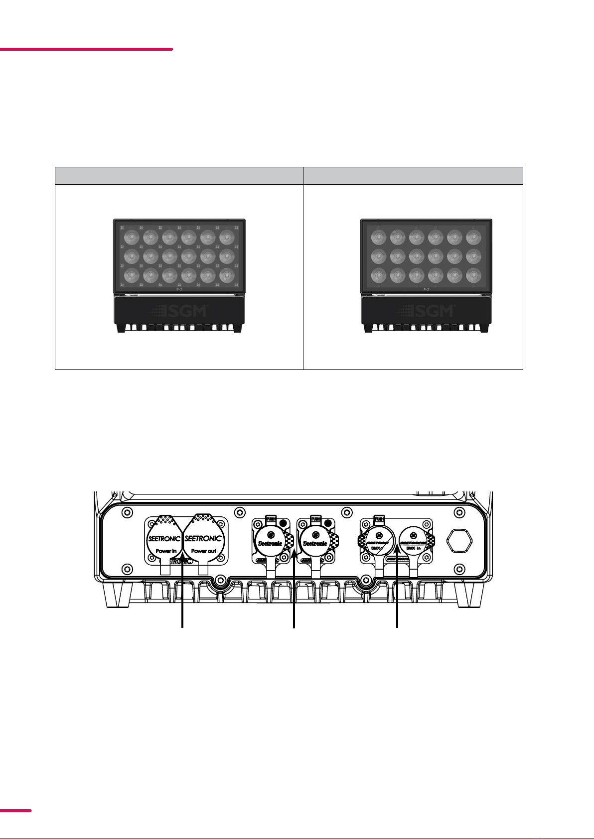
FIXTURE TYPES
CABLING ON WASH AND VISION
CONTROL OPTIONS
P-3 VISION P-3 WASH
Power In/Out Ethernet In/Out DMX In/Out
• DMX
• sACN
• Art-Net
• Wireless DMX (CRMX)
9Product Version 1.0 | Revision A | Released 2023-10-19
INSTALLATION P3
Illustrations might vary from received products. This is subject to change without notice.
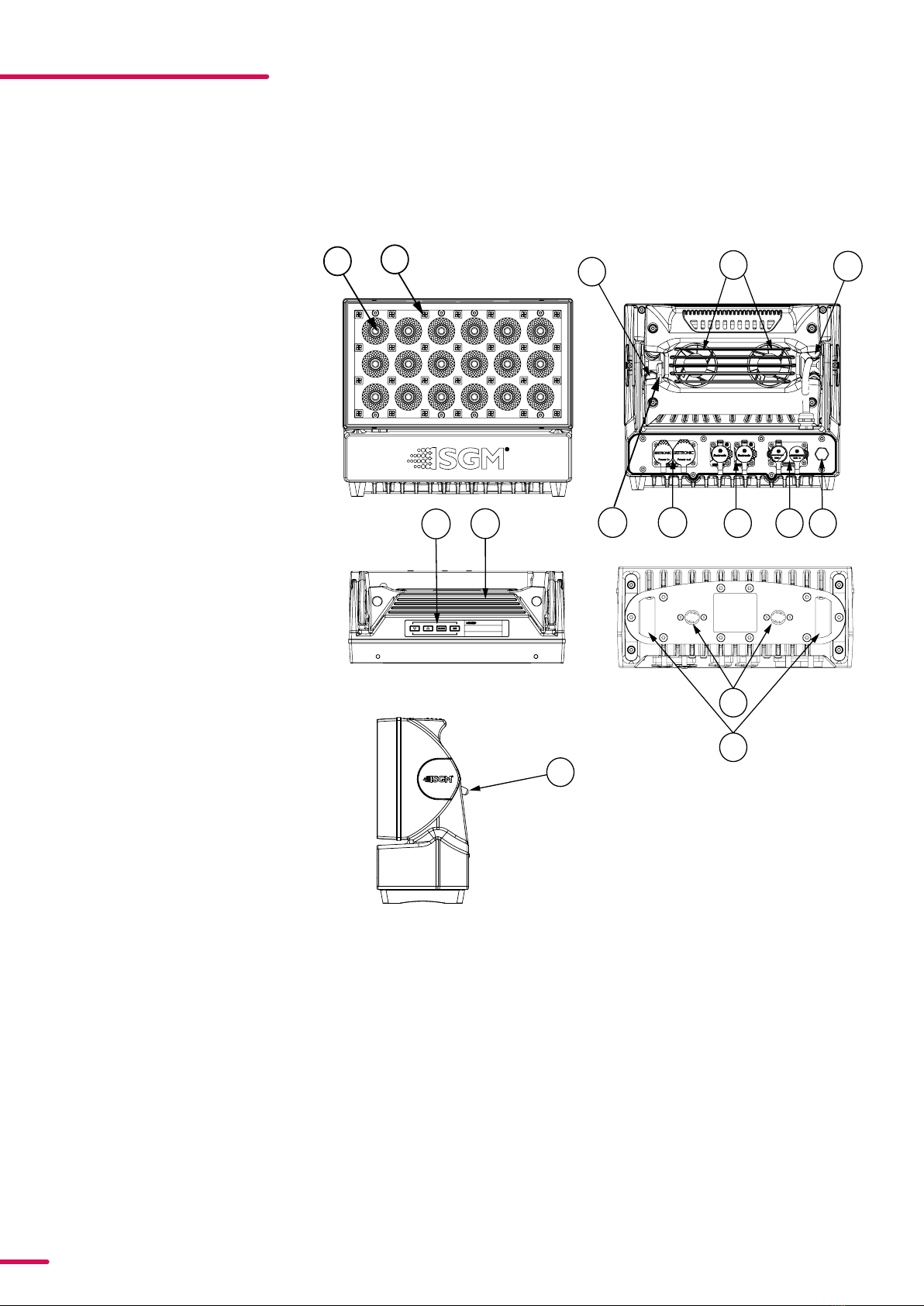
IDENTIFICATION AND TERMINOLOGY OF P3 VISION
AB
A: 24 x RGBW LEDs
B: 28 x RGB pixels
C: GORE-TEX membrane
D: Cooling fans
E: Dehumidifier
F: Control Panel
G: Handle
H: Tilt Lock
I: Power In/Out
J: Ethernet In/Out
K: DMX In/Out
L: Holes for Omega bracket
M: Safety wire attachment point
D
C
JC
K
L
M
I
F
E
G
H
H
10 Product Version 1.0 | Revision A | Released 2023-10-19
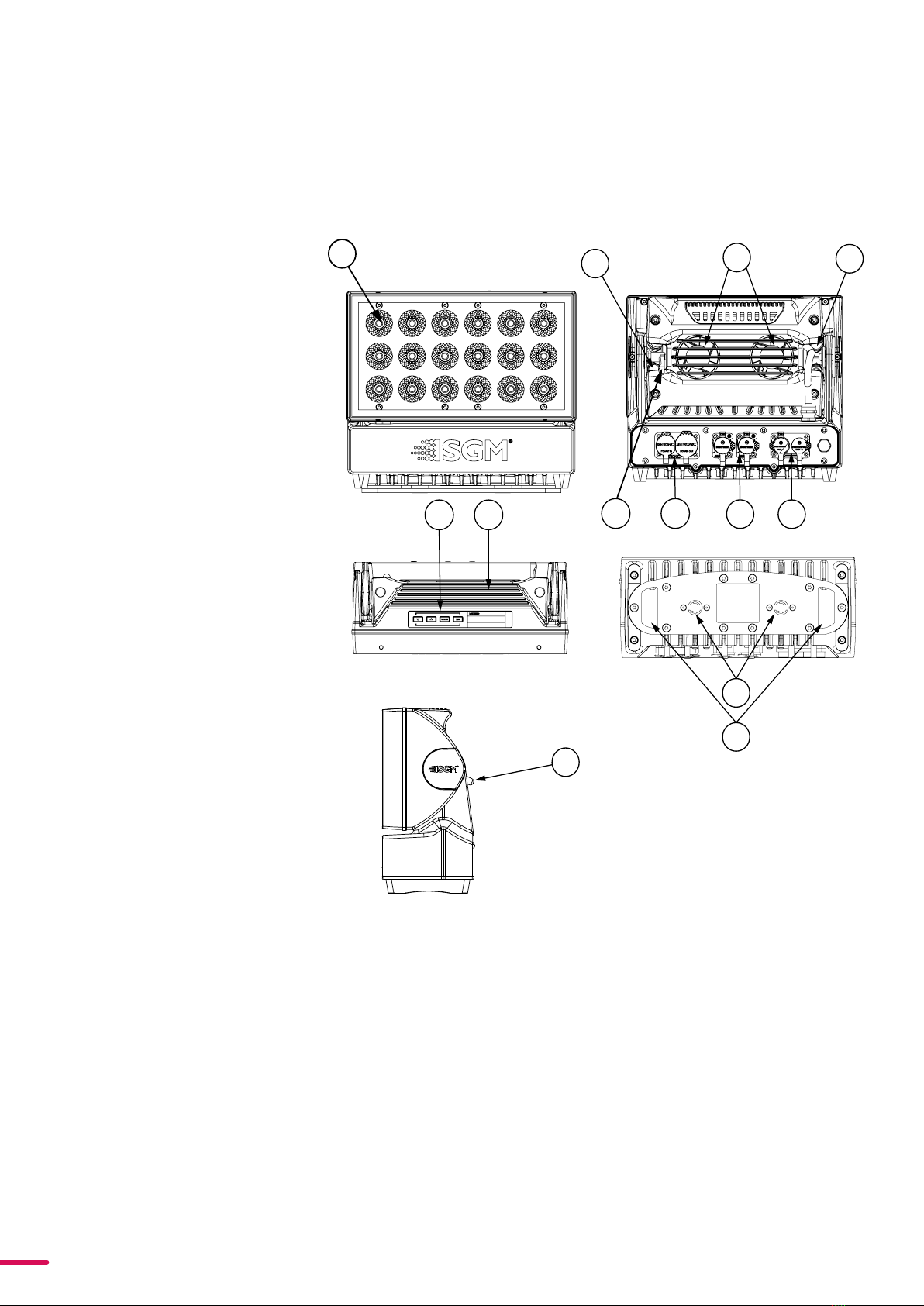
IDENTIFICATION AND TERMINOLOGY OF P3 WASH
AB
A: 24 x RGBW LEDs
B: GORE-TEX membrane
C: Cooling fans
D: Dehumidifier
E: Control Panel
F: Handle
G: Tilt Lock
H: Power In/Out
I: Ethernet In/Out
J: DMX In/Out
K: Holes for Omega bracket / M-10 screws (x2)
L: Safety wire attachment point
K
L
FI
G
G
HJ
E
CD

11 Product Version 1.0 | Revision A | Released 2023-10-19
UNPACKING
Before permanent mounting, ensure the fixture is not visibly damaged and that all parts and components are pres-
ent. Testing the fixture for proper function is also recommended. During testing, configuration and addressing can
be done. The P-3 is an addressable product and is most efficiently configured before installation. This is especially true
in installations where the fixtures will be in inaccessible areas.
Configuration can be done either via the display or by using SGM Configuration software. This PC based software is
available for download from the SGM website. Once all fixtures, parts and software are available, configuration and
installation can begin.
APPLICATION CONSIDERATIONS
When selecting a location for the device, ensure that:
• It is situated away from public thoroughfares and protected from contact with people.
• It is not immersed in water.
• It has adequate ventilation
The standard fixture is IP66-rated and is designed for both indoor and outdoor events. This means that it is protected
from:
• Dust, to the degree that dust cannot enter the fixture in sufficient quantities as to interfere with its operation.
• Lower pressure water jets from any direction.
When using standard fixtures outdoors or in wet locations, ensure that:
• The DMX connection out of the last fixture in a chain is properly sealed, in accordance with the ingress protec-
tion (IP) requirements.
• The DMX out of the last fixture is terminated with a 120 Ohm resistor between pin 2 and 3 (as per RS485 stand-
ards).
HANDLING AND TRANSPORTATION
Always use the supplied packaging or suitable flight case for transportation and storage. Never carry the fixture by
connected cables or wires.

12 Product Version 1.0 | Revision A | Released 2023-10-19
RIGGING
The P-3 can be installed in any orientation, in any free-air cooled application. There are numerous mounting options
via 3 adjustable brackets.
Start the standard rigging process by blocking the lower working area, and make sure the work is performed from a
stable platform.
3,150in
80mm
4,882in
124mm
4,173in
106mm
10,079in
256mm
11,417in
290mm
2,441in
62mm
A
Figure 1 : Dimensions for base locking points
All SGM fixtures have locking points in the base for installation and rigging. In both standard and POI fixtures, the
distance between the points from center to center is always 106 mm. Standard versions include 1/4 turn fasteners to
mount SGM omega brackets. POI versions come with M-10 captive nuts for M-10 screws.
Always use the supplied omega bracket to rig a standard fixture. Lock the bracket with the 1/4-turn fasteners.
PLEASE NOTE! 14TURN FASTENERS ARE ONLY LOCKED WHEN TURNED FULLY CLOCKWISE. DEPENDING ON
THE STRUCTURE, PLEASE USE APPROPRIATE AND SECURE METHODS FOR MOUNTING THE OMEGA BRACKETS.
13 Product Version 1.0 | Revision A | Released 2023-10-19
Step 1. Check that the clamp/bracket is undam-
aged. Supporting structure should be capable of
bearing at least 10 times the weight of all installed
fixtures, lamps, cables etc.
Step 2. Bolt a clamp or bracket securely to the ome-
ga bracket with a M12 bolt (min. grade 8.8) and a
lock nut. For longer term installations, choose out-
door-rated hardware.
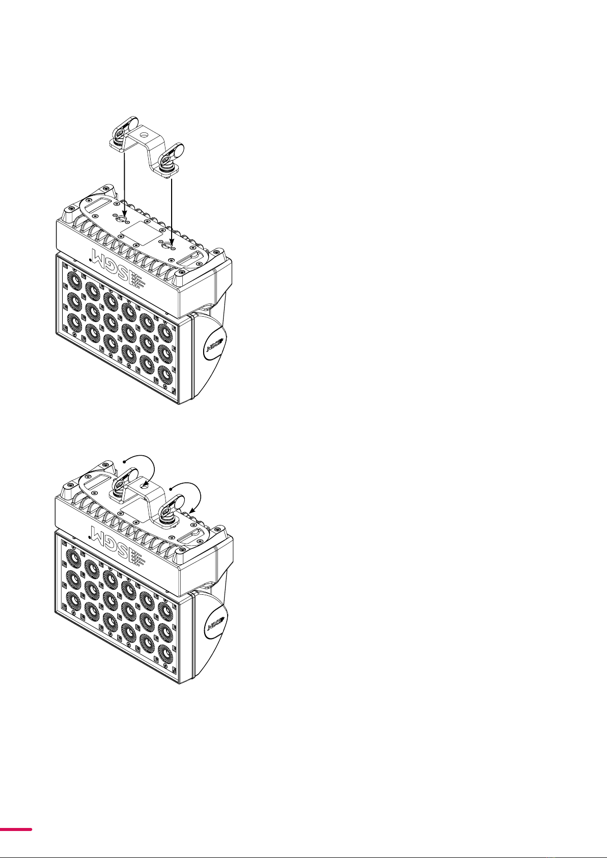
Step 3. Align the omega bracket with the fixture
base. For standard Omega Bracket, insert the fas-
teners into the fixture base bracket, and turn both
levers a full 1/4 turn clockwise to lock. (When using
the POI Omega Bracket, insert the included M-10
screws through the bracket holes and tighten
them with a M-10 key until they are fully attached
to the base.
Step 4. Hang the fixture on a truss or other struc-
ture. Tighten the clamp/bracket.
Step 5. Verify that there are no combustible materi-
als, cables, or surfaces to be illuminated within 0.3
m (12 in.) of the fixture.
Step 6. Check that there is no risk of the head/yoke
colliding with other fixtures or structures.
Figure 3 : Installing the P-3
Figure 2: Installing the P-3
OMEGA BRACKET
14 Product Version 1.0 | Revision A | Released 2023-10-19
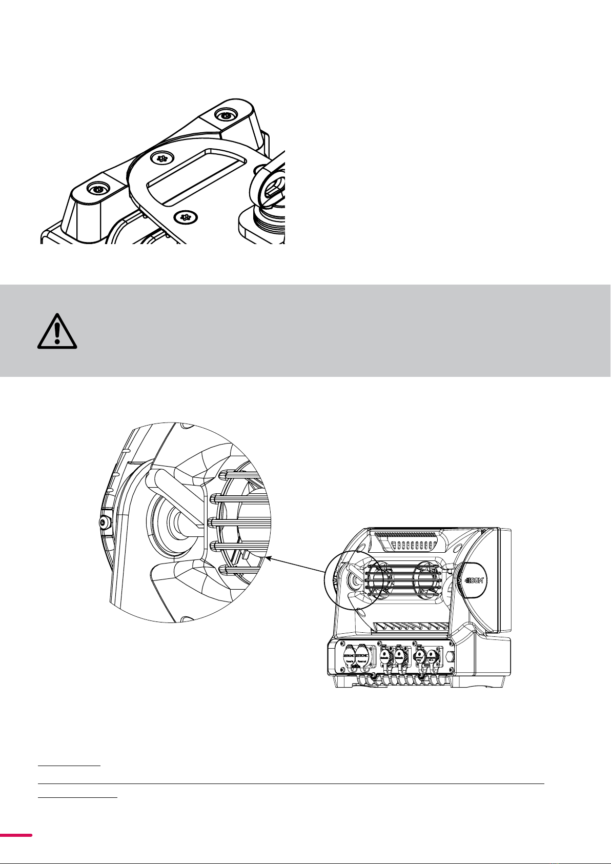
Fasten a safety wire (not shown) between the load-bear-
ing support structure and the safety wire attachment
point on the device.
The safety cable (not included in the package) must:
• Bear at least 10 times the weight of the device
(SWL).
• Have a minimum gauge of 4 mm.
• Have a maximum length (free fall) = 30 cm (12 in.).
SAFETY WIRE
SAFETY WIRE
Figure 4 : Safety wire attachment point
Pushing the lever on the left hand side of the fixture will tighten the tilt. it may take several rotations to fully lock the
fixture head in place.
CAUTION!
ALWAYS LEAVE A FIXTURE TO COOL OFF FOR 15 MINUTES AFTER OPERATION BEFORE
HANDLING.
SAFETY WIRE
TILT LOCK
WARNING! ALWAYS SECURE AN ELEVATED FIXTURE WITH A SAFETY WIRE.
ALWAYS USE A SAFETY WIRE OF A GRADE AISI 316 STEEL. MAKE SURE THE
SLACK OF THE SAFETY WIRE IS AT A MINIMUM. NEVER USE THE YOKE/
HANDLE FOR SECONDARY ATTACHMENT.
Figure 5: Tilt Lock

15 Product Version 1.0 | Revision A | Released 2023-10-19
ARRAYING
PLEASE NOTE! APPLICABLE TO P3 VISION AND WASH VARIANTS ONLY.
The P-3 Vision and Wash are designed to work with an arraying bracket which locks the fixtures together in x and y
axis. This bracket aligns the fixtures only, they are not designed to be self-supporting.
PLEASE NOTE: NEVER RIG FIXTURES FROM THE ARRAYING BRACKET WITHOUT A SUPPORTING STRUCTURE.
Step 2:
Attach fixtures to the arraying brackets using
the quarter turn fasteners one line at a time. This
is so that all fixtures can be configured and veri-
fied via the control screen and keypad.
Step 3:
Cable each line of fixtures and verify boot and
configuration settings are correct.
Repeat steps 2 and 3 for grid style and other x &
y axis shapes.
Step 1:
Create a substructure which is spaced appropri-
ately to have the arraying brackets connected
together in the shape desired.
All connecting hardware must be sized and rat-
ed to safely hold the weight of the fixture and
the arraying bracket together.
Figure 6: Installation with arraying brackets

16 Product Version 1.0 | Revision A | Released 2023-10-19
Color
Black
White
green/yellow
Conductor
live
neutral
ground (earth)
Symbol
or
L
N
Wire
(L2)
Figure 8: Connecting AC Power/P-1 power cable 8 mm
P3 VISION AND WASH POWER
P3 VISION AND WASH DATA
The power cable color coding is given in figure 8:
• Connect the black wire to live
• Connect the white wire to neutral
• Connect the green/yellow wire to ground (earth)
The power cable must be fitted with a grounded connector intended for exterior use.
PLEASE NOTE! PROTECTIVE CAPS MUST BE SECURELY MOUNTED ON ANY UNUSED CONNECTORS, IN ORDER TO
MAINTAIN INGRESS PROTECTION IP RATING.
CAUTION! DO NOT CONNECT THE FIXTURE TO AN ELECTRICAL DIMMER SYSTEM, AS DOING
SO MAY CAUSE DAMAGE
The fixture is controllable using a DMX, sACN or Art-Net control device, and can be connected using either a DMX
cable, Ethercon style cable, or via the fixture’s built-in CRMX wireless receiver system.
POWER AND DATA
The P-3 series has cable and connectors for power and signal located on the back.
The power input required is 100–277 V, 50/ 60 Hz AC mains power supply, and draws a maximum of 360 Watts (P-3
Vision) or 330W (P-3 Wash) . Both are connected to power via “Powercon” type connectors. Power plug is as per local
code.
Power In/Out Ethernet In/Out DMX In/Out
Figure 7: Power and Data connectors

17 Product Version 1.0 | Revision A | Released 2023-10-19
CONNECTING A WIRELESS TRANSMITTER
The fixture is designed to look for wireless transmitters in ‘connect’ state when this option is not yet enabled. The fix-
ture comes tested for wireless functionality from the factory, therefore the beginning of the pairing process is discon-
nect from the factory wireless DMX transceiver.
To connect the fixture to a wireless transmitter:
1. Log off the currently paired wireless transmitter. Go to SETTINGS → WIRELESS DMX → LOG OFF in the menu.
Fixture confirms logged off.
2. Initialize connection on the wireless transmitter.
3. Confirm that the fixture has paired with the wireless transmitter.
SIGNAL PRIORITY
The fixture can be paired to an active wireless transmitter while also being connected to a cabled DMX or ethernet
signal. By default, the fixture will prioritize cabled DMX signal. If there is not cabled DMX signal, it will use the ethernet
signal. If it is also not receiving any ethernet signal, it will switch to wireless DMX.
Through the Settings menu in the display or RDM, this can be changed so that the fixture will prioritize wireless DMX
over Cabled DMX and ethernet.
The active input type is displayed in the top right corner of the display. The wireless signal strength can be checked
from the System menu in the display or via RDM by using an external RDM device.
DMX
When using a cabled DMX system, connect the DMX-In cable to the input connector and DMX-Out cable to the out-
put. Both are located on the rear of the fixture’s base (chassis mounted male and female 5-pin XLR plugs).
For outdoor installations, use only IP65-rated XLR connectors suitable for outdoor use. Terminate the DMX out cable
of the last fixture in the data link with a 120-ohm DMX termination.
PLEASE NOTE! SGM FIXTURES PROVIDE A PASSIVE DMX THRU SIGNAL AS DMX OUT, INSTEAD OF AN ACTIVE
OUTPUT SIGNAL.
ETHERCON
Using sACN or Art-Net is done through the ethernet connectors. These are compatible with all Ethercon or RJ45 style
connectors. The 2 ethernet ports can serve in either a daisy chain topology or can be fed directly with the ethernet
lines, providing a double input for ethernet protocols. For outdoor installations, use only IP65-rated XLR connectors
suitable for outdoor use. In a setup where the ethernet ports are in a daisy chain, the fixture will still pass through the
ethernet signal in the event the fixture loses power.

18 Product Version 1.0 | Revision A | Released 2023-10-19
USER INTERFACE
The fixture can be set up by using the control panel and OLED multi-line display on fixture’s head or through RDM.
The OLED display shows the current status and menu of the fixture. It is used to configure individual fixture settings
and read error messages. The complete list of the menu and all commands available are listed in “Control menu”.
Before turning on the fixture, make sure the power cable is properly connected. When the fixture is powered on it will
boot and reset before displaying the selected operating mode and DMX start address. Navigate through the menus
and options using the arrow buttons, and select items using the ENTER button.
USING THE DISPLAY PANEL
• Press the ‘ENTER’ button to access the menu or make a selection.
• Press the arrow buttons to scroll up and down in the menus.
• Press the ‘ESC’ button to take a step back in the menu.
Lorem ipsum dolor sit
6CH CTC MODE 101 (107)
DMX
ESC ENTER
Figure 9: OLED display and control panel
SHORTCUTS
• ESC + ENTER: Press ENTER to confirm factory defaults.
• ESC + UP: Press ENTER to start LED test.
• UP + DOWN arrows simultaneously = flip the display upside-down.
• ENTER + DOWN (hold down for 10 sec): Keypad unlock

19 Product Version 1.0 | Revision A | Released 2023-10-19
DISPLAY
OPERATIONAL MODE A
Displays the current mode (quick color, stand-alone, or
DMX mode). The fixture is set by default to be controlled
in DMX mode.
FIXTURE UNIVERSE B
Displays the current fixture universe. The universe is al-
tered directly from this view.
DMX ADDRESS C
Displays the current DMX address. The DMX address is al-
tered directly from this view.
Figure 10: Display
EXTERNAL DATA PROTOCOL D
Shows the external data protocol.
• When ‘DMX’ is displayed: the fixture responds to data received through cabled DMX.
• When ‘CRMX’ is displayed: the fixture responds to data received through wireless DMX.
• When ‘ART’ is displayed: the fixture responds to data received through Art-Net.
• When ‘sACN‘ is displayed: the fixture responds to data received through sACN.
When ‘-H‘ is shown after one of the above protocols this is an indication that Hybrid Mode is enabled.
EXTERNAL DATA INDICATOR E
The DMX signal indicator will flash when the DMX signal is received.
NEXT AVAILABLE ADDRESS F
The next available DMX address will show immediately, depending on the fixture’s DMX footprint.
INFORMATION PANEL G
The information panel is accessed by pressing ESC. It functions
as a way to quickly get an overview of errors, notifications and
important settings. Errors will always be shown first, followed
by a divider line. All other information such as custom PWM
frequency, Vision universe and address, ... will be shown below
the divider line. The current page and the total amount of pag-
es of information is shown in the top right corner of the display.
WARNING INDICATOR
If any errors are detected, the exclamation point will alternate
with the current display for easy detection.
To read the error message,do to the information panel by
pressing ESC.
A
G
B C D
F
E
Figure 11: Information panel
Figure 12: Warning indicator

20 Product Version 1.0 | Revision A | Released 2023-10-19
P-3 Vision and Wash are configured using either the user interface or SGM software; the SGM software, the SGM RDM
Addressing Tool. This software is Windows® PC based and connects to the fixtures via DMX512/RDM using the SGM
USB uploader cable.
ABOUT DMX
The fixture can be controlled using signals sent by a DMX controller on a number of DMX channels.
DMX is the USITT DMX512-A standard, based on the RS-485 standard. The signal is sent as DMX data from a console
(or a controller) to the fixtures via a shielded twisted pair cable designed for RS-485 devices.
The cables can be daisy chained between the fixtures, and up to 32 fixtures can be connected on the same DMX link.
Up to 300 m. (~1000ft.) of cable is achievable with high quality DMX cables. All DMX links must be terminated by con-
necting a DMX termination plug to the last fixture´s 5 pin DMX out connector.
PLEASE NOTE! STANDARD MICROPHONE CABLE IS NOT SUITABLE FOR TRANSMITTING DMX. UP TO 32 FIXTURES
CAN BE LINKED TO THE SAME DMX CHAIN. ADDITIONAL FIXTURES WILL OVERLOAD THE LINK.
DMX START ADDRESS
The fixture can be operated in different DMX modes. For any of the modes, the first channel used to receive data from
a DMX control device is known as the DMX start address.
For independent control, each fixture must be assigned its own DMX start address. For example, if the first RGBW
fixture is set to 6ch CTC DMX mode with a start DMX address of 101, the following RGBW fixture in the DMX chain
should then be set to a DMX address of 107. As the first fixture uses all the first 6 DMX channels, including channel 101,
the next available channel is 107 (101+6=107 >> 107).
If two or more fixtures have the same DMX start address, they will behave identically. Incorrect settings will result in
unpredictable responses from the lighting controller. Address sharing can be useful for diagnostic purposes and sym-
metrical control.
SETTING UNIVERSE AND ADDRESS
The fixture universe and address are shown on the
OLED display in the control panel. To change the
universe and address, start by pressing the up or
down button once. Use the up and down button to
first change the universe. When the desired uni-
verse is shown press ENTER to start changing the
address by using the up and down buttons. Once
the correct address is shown press ENTER to store
the universe and address. Note that if the fixture is
controlled through cabled/wireless DMX, the universe setting has no effect. The universe is only used if the fixture is
controlled via Art-Net or sACN using the ethernet port. For your convenience, the next available DMX address is dis-
played in the bottom right corner of the display. See "User Interface" on page 18 for instructions on using the display
panel. The fixture also offers the option to set the universe and address through RDM.
CONFIGURATION
AddressUniverse
Next available
Address
SETTING DMX MODE
From firmware version 3 onwards, a legacy and standard set of DMX modes are available. To select the DMX mode of
choice, a menu layer is implemented. To access the modes:
1. Press [ENTER]
2. “MODE” is displayed, Press [ENTER]
3. “Select Mode” and current DMX mode is displayed.
4.Press [Up] or [Down] to enter DMX Operation
Mode.
5. Press [ENTER]
6. Press [Up] or [Down] to select “Standard” or “Lega-
cy” DMX modes.
7. Press [ENTER]
8. Press [ESC]
9. Press [Up] or [Down] to navigate to list of DMX
modes.
10. Press [ENTER]
11.Navigate to DMX mode of choice by pressing [UP]
or [DOWN]
12. Press [ENTER]
PLEASE NOTE: DMX CHARTS FOR ALL MODES ARE AVAILABLE FOR DOWNLOAD AT WWW.SGMLIGHT.COM OR
BY EMAILING SUPPORT AT SUPPORTSGMLIGHT.COM
Figure 13: Setting universe and address
Table of contents
Other SGM Lighting Equipment manuals


Popular Lighting Equipment manuals by other brands

Vision & Control
Vision & Control A-DIF-60x90-IR850-SL Instructions for use

Gradus Group
Gradus Group Impact FF-OSB60 instructions

GARANT
GARANT 081448 200 user guide

Daintree
Daintree GE current Evolve EFC1 Series installation guide

Pentair
Pentair SOLEO CL Installation and user guide

unios
unios Linear Series quick start guide


