ShadeLab SHAN User manual

Assembly manual


INDEX
1 - INTRODUCTION ..............................................................p. 4
1.1 - Symbols used in the manual ....................................................... p. 4
1.2 - Personnel requirements .............................................................. p. 4
1.3 - Equipment necessary .................................................................p. 5
1.4 - Prior to assembly ........................................................................ p. 5
2 - SAFETY .......................................................................p. 6
2.1 - General safety information.......................................................... p. 6
2.2 - Working environment ................................................................. p. 6
3 - ASSEMBLY TECHNICAL TABLES ..........................................p. 7
3.1 - Table of minimum dimensions ....................................................p. 7
3.2 - Motor power table ...................................................................... p. 7
3.3 - Table of cutting dimensions ........................................................ p. 8
3.4 - Table of arms-central support brackets ...................................... p. 9
4 - SHAN COMPONENTS AND DIAGRAMS ..................................p. 11
4.1 - Tilting diagrams .......................................................................... p. 11
4.2 - Awning components ................................................................... p. 12
4.3 - Material necessary for assembly ................................................ p.
13
5 - AWNING ASSEMBLY ........................................................p. 14
6 - REGULATING THE AWNING ................................................p. 21
6.1 - Troubleshooting .......................................................................... p. 23
7 - REMOVING AND PACKING THE AWNING ................................p. 25
7.1 - Removing .................................................................................... p. 25
7.2 - Packing ....................................................................................... p. 25

4 | | ASSEMBLY
1 - INTRODUCTION
This “assembly manual” for SHAN awnings has been produced by SHADELAB to sup-
ply the indications necessary for the operations of assembling the components that
make up the product.
Assembly must be carried out by personnel with suitable technical and professional
qualifications, in accordance with the respective national laws or regulations (see Par.
1.2 “Personnel requirements”).
It is forbidden to eliminate, rewrite or alter the pages in the manual and their content.
This manual must be kept intact in all its parts, in an easily accessible place.
SHADELAB reserves the right to update the production and the respective manuals,
without being obliged to update the previous production and manuals.
SHADELAB reserves all rights to this manual: no total or partial reproduction is al-
lowed without authorisation in writing.
1.1 - Symbols used in the manual
Shown below are the WARNING symbols used in this manual:
IMPORTANT
Indications and advice to be observed to ensure a correct use of the awning. Failure to
follow these indications may endanger the integrity and/or resistance of the product.
ATTENTION
DANGER FOR THE OPERATOR! Instructions and indications to be assessed and fol-
lowed with care. Failure to follow these indications may endanger personal safety.
1.2 - Personnel requirements
The personnel appointed to perform this operation must possess a technical knowl-
edge of the product, acquired by assembling similar products for at least one year or
after having followed a suitable technical training course.

| ASSEMBLY | 5
1.3 - Equipment necessary
To ensure the correct assembly of the mechanical part, of the textile part, and conse-
quently the optimum operation of the finished product, it is necessary to be in pos-
session of the following equipment:
»fabric rolling frame;
»awning assembly frame with arms and vertically movable positioning bar;
»electric and pneumatic screwdriver;
»complete set of tools.
1.4 - Before starting assembly
IMPORTANT
Some components must be cut to suit the dimensions of the awning that is to be ob-
tained (see Par. 3.3 “Table of cutting dimensions”).

6 | | ASSEMBLY
2 - SAFETY
2.1 - General safety information
Follow these safety precautions:
ATTENTION
Wear the garments and personal protection equipment contemplated by the safety
regulations in force for the workplace (protective helmet, gloves, etc.).
ATTENTION
It is forbidden to use the awning to support yourself: risk of serious personal injury and
of damage to the awning.
IMPORTANT
Do not lay objects on the awning.
IMPORTANT
This manual is an integral part of the product. Before assembly, carefully read all the
instructions given in this manual.
IMPORTANT
SHADELAB guarantees the EC marking only for products supplied by the company itself.
If any parts have to be replaced with other components not guaranteed by SHADELAB,
the product guarantee will automatically become void and SHADELAB shall not answer
for any malfunctions of the product.
ATTENTION
Some awning components are constantly subject to strong pressure (arms) and, if the
instructions in this manual are not carefully followed, these components may cause
serious harm to persons and animals and damage to objects.
ATTENTION
NEVER reuse the arm lock after removing it.
2.2 - Working environment
At the moment of assembly, good natural and/or artificial lighting must be created in
the place where the work is being done.

| ASSEMBLY | 7
3 - ASSEMBLY TECHNICAL TABLES
3.1 - Table of minimum dimensions
Shan minimum dimensions
Arm projection [cm] Minimum width [cm]
150 199
175 224
200 249
225 274
250 299
275 324
300 349
325 374
350 399
375 424
400 449
Tab.1
3.2 - Motor power table
Width [cm]
200 300 400 500 600 700
Projections [cm]
150 15/17 N/m
175
25 N/m
200
225
250
30 N/m
275
300
325 35/40 N/m
350
375 50 N/m
400 60 N/m
Tab.2
IMPORTANT
For this awning model use motors with an electronic limit switch.

8 | | ASSEMBLY
3.3 - Table of cutting dimensions
Cutting dimensions
Component Type of control Size/measurement ratio
in [mm]
Cover
NICE MOTOR L -40
NICE MOTOR WITH EMERGENCY MANOEUVRE L -40
SOMFY MOTOR L -40
SOMFY MOTOR WITH EMERGENCY MANOEUVRE L -40
BECKER MOTOR L -40
BECKER MOTOR WITH EMERGENCY MANOEUVRE L -40
Cassette
NICE MOTOR L -40
NICE MOTOR WITH EMERGENCY MANOEUVRE L -40
SOMFY MOTOR L -40
SOMFY MOTOR WITH EMERGENCY MANOEUVRE L -40
BECKER MOTOR L -40
BECKER MOTOR WITH EMERGENCY MANOEUVRE L -40
Terminal bar
NICE MOTOR L -40
NICE MOTOR WITH EMERGENCY MANOEUVRE L -40
SOMFY MOTOR L -40
SOMFY MOTOR WITH EMERGENCY MANOEUVRE L -40
BECKER MOTOR L -40
BECKER MOTOR WITH EMERGENCY MANOEUVRE L -40
Saddle
NICE MOTOR L -40
NICE MOTOR WITH EMERGENCY MANOEUVRE L -40
SOMFY MOTOR L -40
SOMFY MOTOR WITH EMERGENCY MANOEUVRE L -40
BECKER MOTOR L -40
BECKER MOTOR WITH EMERGENCY MANOEUVRE L -40
Roller tube
NICE MOTOR L -130
NICE MOTOR WITH EMERGENCY MANOEUVRE L -130
SOMFY MOTOR L -129
SOMFY MOTOR WITH EMERGENCY MANOEUVRE L -134
BECKER MOTOR L -129
BECKER MOTOR WITH EMERGENCY MANOEUVRE L -136
Fabric
NICE MOTOR L -150
NICE MOTOR WITH EMERGENCY MANOEUVRE L -150
SOMFY MOTOR L -149
SOMFY MOTOR WITH EMERGENCY MANOEUVRE L -154
BECKER MOTOR L -149
BECKER MOTOR WITH EMERGENCY MANOEUVRE L -156
Tab.3

| ASSEMBLY | 9
3.4 - Table of arms-central support brackets
Projections [cm]
Width [cm]
2 arms
251-300 301-350 351-400 401-450 451-500 501-550 (*) 551-600 (*)
A
max
n°
brackets
A
max
n°
brackets
A
max
n°
brackets
A
max
n°
brackets
A
max
n°
brackets
A
max
n°
brackets
A
max
n°
brackets
150 40 2 40 2 50 2 50 3 50 3 50 3 60 5
175 30 2 40 2 50 2 50 3 50 3 50 3 60 5
200 20 2 30 2 50 2 50 3 50 3 50 3 60 5
225 10 2 30 2 50 2 50 3 50 3 50 3 60 5
250 6 2 20 2 50 2 50 3 50 3 50 3 60 5
275 - - 10 2 40 2 50 3 50 3 50 3 60 5
300 - - 6 2 20 2 50 3 50 3 50 3 60 5
325 - - - - 10 2 40 3 50 3 50 3 60 5
350(*) - - - - 6 3 30 3 50 3 50 3 60 5
375(*) - - - - - - 10 3 40 3 50 3 60 5
400(*) - - - - - - 6 3 20 3 50 3 60 5
* add a central support Tab.4
fig.1
Cassette profile edge
Dimension B = 8 ÷ 9 cm.

10 | | ASSEMBLY
Projections [cm]
Width [cm]
601-650 (*) 651-700 (*)
3 arms 4 arms
n° brackets
3 arms 4 arms
n° brackets
A
max BA
max BA
max BA
max B
150 50 182 50 170 5 50 200 50 185 5
175 50 182 40 175 5 50 200 50 185 5
200 50 182 20 180 5 50 200 30 195 5
225 50 182 10 175 5 50 200 10 205 5
250 50 182 6 170 5 50 200 10 190 5
275 50 182 6 160 5 50 200 10 180 5
300 50 182 - - 5 50 200 6 172 5
325 30 195 - - 5 30 210 - - 5
350(*) 10 209 - - 5 20 218 - - 5
375(*) 10 209 - - 5 20 218 - - 5
400(*) - - - - 5 6 228 - - 5
* add a central support Tab.5
fig.2
Cassette profile edge
Cassette profile edge
| ASSEMBLY | 11
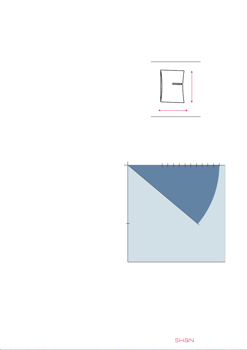
PROJECTION
HEIGHT
262
400
375
350
325
300
275
250
225
200
175
150
0°
40°
258
185
4 - SHAN COMPONENTS AND DIAGRAMS
4.1 - Tilting diagrams
Dimensions of closed awning
Wall mounting
Arm length and inclination
Wall and roof mounting
RECOMMENDED ARM: URBAN
RECOMMENDED DIMENSIONS: width 600cm - projection 400cm
0° minimum inclination
40° maximum inclination

12 | | ASSEMBLY
4.2 - Awning components
In the system supplied by SHADELAB the customer will find the following compo-
nents already preassembled:
»2 wall brackets (see ref. 1, fig. 3);
»1 LH cassette cap assembly (see ref. 2, fig. 3);
»terminal bar cap (see ref. 3, fig. 3);
»1 RH cassette cap assembly (see ref. 4, fig. 3);
»terminal bar cap (see ref. 5, fig. 3);
»2 roller tube supports (see ref. 6, fig. 3);
»2 arm supports (see ref. 7, fig. 3);
»2 arms (see ref. 8, fig. 3);
»2 terminal bar connecting kits (see ref. 9, fig. 3);
»1 box, comprising:
»terminal bar (front) (see ref. 10, fig. 3);
»cover (top) (see ref. 11, fig. 3);
»cassette (bottom) (see ref. 12, fig. 3);
»saddle (see ref. 13, fig. 3);
»1 central support with conveyor (see ref. 14, fig. 3);
»1 balloon gasket (see ref. 15, fig. 3);
»1 brush (see ref. 16, fig. 3);
»1 plate with pin (see ref. 17, fig. 3);
»1 cap with hole (see ref. 18, fig. 3);
»1 roller tube (see ref. 19, fig. 3);
fig.3
11 1
13
19
118
17
7
8
9
8
10
3
5
9
4
6
15
7
15
6
16
14
2
12

| ASSEMBLY | 13
4.3 - Material necessary for assembly
The following spanners are required to assemble the SHAN awning:
»Allen wrenches (see ref. 1, fig. 4): 3, 5, 8
»Combination spanners (see ref. 2, fig. 4): 10
»Box spanners (see ref. 3, fig. 4): 13
fig.4
1 2 3
14 | | ASSEMBLY
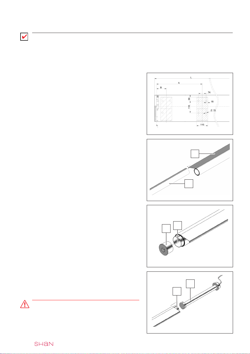
fig.5
5 - AWNING ASSEMBLY
IMPORTANT
Before starting assembly, the fitter must have cut the pieces to size (see tab. 3 para
3.3) .
Define the distance of the brackets (see fig.
5) and position them on the awning assembly
frame.
Assemble the fabric (see ref. 1 fig. 6) with
the roller tube (see ref. 2 fig. 6) and roll it up
completely.
Insert the cap with hole (see ref. 3 fig. 7) on
the side opposite the control (see ref. 4 fig.
7).
fig.6
fig.7
1
2
34
MOTOR-OPERATED AWNING:
Insert the motor (see ref. 5 fig. 8) in the roller
tube (see ref. 6 fig. 8).
ATTENTION
As these instructions are of a general nature,
follow the ones given in the motor manual.
fig.8
6
5
CASSETTE PROFILE EDGE
| ASSEMBLY | 15
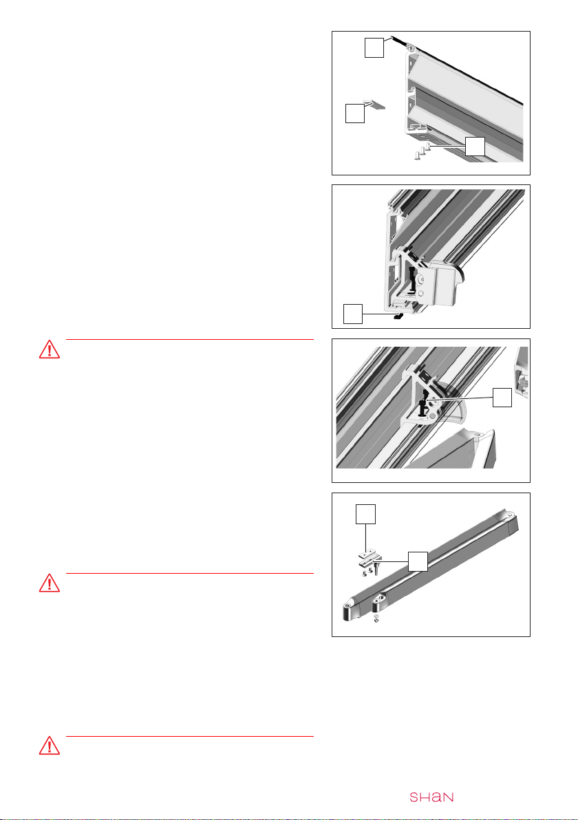
fig.9
fig.10
Insert the gasket (see ref. 7 fig. 9) into the
cassette profile.
Place the cassette profile on the brackets.
Insert the same number of plates (see ref. 8
fig. 9) as there are brackets.
Fix the profile with the screws (see ref. 9 fig.
9).
Position the arm support on the cassette pro-
file in the same position as the bracket.
Insert the same number of plates (see ref. 10
fig. 10) as there are arm/central brackets.
Fix the arm support with the screws.
9
10
ATTENTION
Where necessary, mount the central conveyor
(see ref. 11 fig. 11) (see tab. 3.4); attach the
lower conveyor to the cassette and the upper
one to the terminal bar.
Preassemble the plate (see ref. 12 fig. 12) in
the terminal bar connecting kit (see ref. 13
fig. 12), (Allen wrench 5). The screws must
not be fully tightened.
ATTENTION
The arm is provided with a safety band that
blocks the tightening mechanism. Do not
remove this band until the awning has been
completely assembled. Failure to respect the
correct assembly procedure may cause seri-
ous harm to persons and animals and damage
to objects in the vicinity.
ATTENTION
NEVER reuse the arm lock after removing it.
fig.11
fig.12
12
13
7
8
11

16 | | ASSEMBLY
Place the cam (see ref. 16 fig. 15) on the side
of the corresponding arm (LH or RH).
Place the spring (see ref. 17 fig. 15) and the
lock pin (see ref. 18 fig. 15) in the hole of the
lever.
Insert the arm with the cam mounted in the
lever.
Insert the pin of the arm in the lever (see ref.
19 fig. 15).
ATTENTION
The pin of the arm has a cam and must be
mounted in the lever of the arm support as
shown in fig. 14.
Assemble the plate with pin (see ref. 20 fig.
16) onto the roller support (see ref. 21 fig.
16) on the opposite side of the control (Allen
wrench 10).
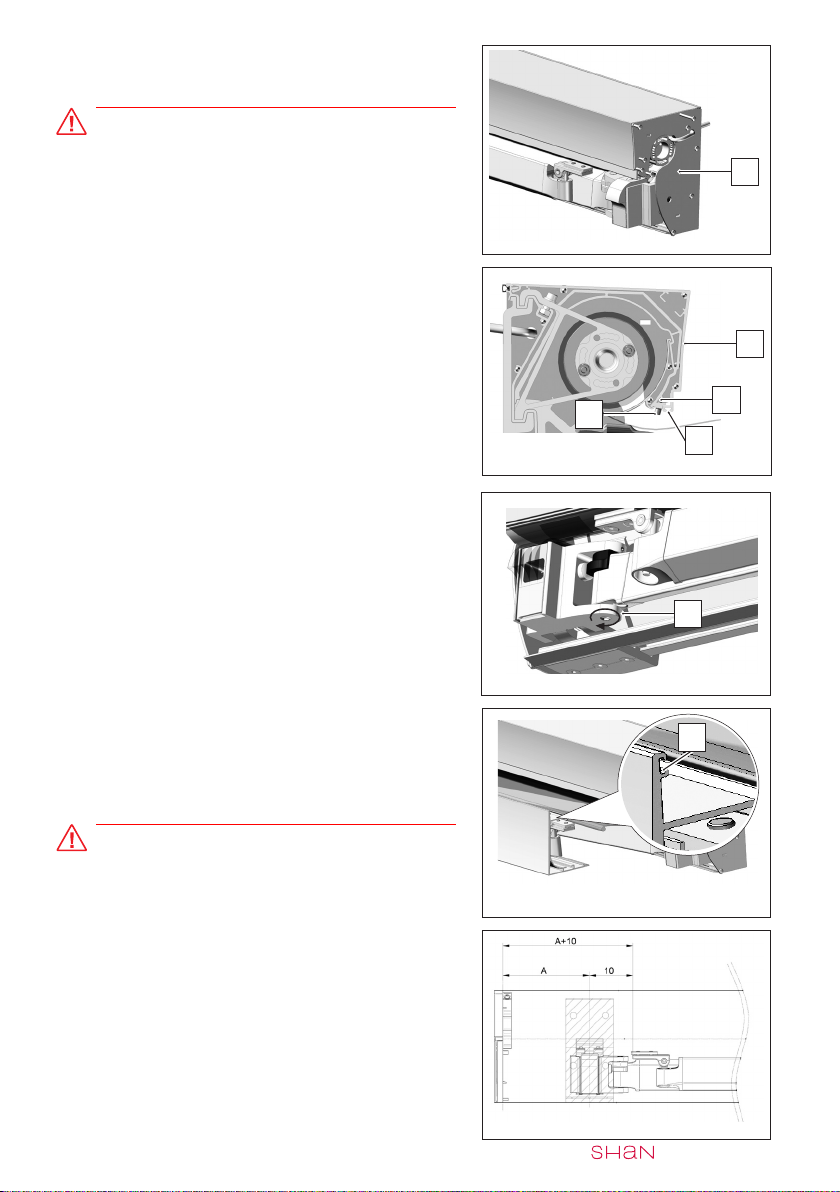
Assemble the motor plate (see ref. 22 fig. 17),
(Allen wrench 10).
fig.17
fig.16
fig.15
fig.14
21
20
16
17
19
18
22
Fit the terminal bar connecting kit (see ref. 14
fig. 13) onto the end of the arm (see ref. 15
fig. 14), (box spanner 13).
ATTENTION
Ensure that the two kits are correctly fixed to
the ends of the arms.
fig.13
14
15

| ASSEMBLY | 17
Fix the roller support (see ref. 23 fig. 18) on
the opposite side to the motor (hex wrench
5).
ATTENTION
Before inserting the second roller support,
the one on the control side, insert all the M6
nuts in the slot of the cassette profile on the
respective supports of the cover to assemble.
Assemble the roller tube complete with the
fabric previously wound with the roller sup-
port (see ref. 24 fig. 19) and the motor.
Mark the position of all the fabric stitches on
the saddle profile (see ref. 27 fig. 21).
Thoroughly clean the surface.
Remove the film from the self-lubricating strip
(see ref. 28 fig. 21).
Attach the self-lubricating strip at the mark.
Start attaching it from the outside of the pro-
file.
Place the saddle profile (see ref. 25 fig. 20)
near the fabric.
Mark the positions of all the stitches on the
profile (see ref. 26 fig. 20) of the fabric.
fig.19
fig.20
fig.18
23
24
25
26
26
28
27
fig.22
Attach the remaining part of the self-lubricat-
ing strip to the inside of the profile.
fig.21

18 | | ASSEMBLY
Position the cover support with saddle profile
on the cassette (see ref. 30 fig. 24).
(for projections in excess of 3 m, partly un-
wind the fabric to facilitate the operation).
Secure the supports to the cassette with the
screws (see ref. 31 fig. 24).
Fix one of the two end plates (see ref. 32 fig.
25) to the cassette.
Push the saddle profile against the plate to
centre it on the awning.
Secure the saddle profile to the supports with
the two dowels (see ref. 33 fig. 26).
ATTENTION
Do not overtighten the dowels; stop when the
profile is blocked.
fig.26
fig.25
Assemble the saddle profile (see ref. 29 fig.
23) with the cover supports.
The number of cover supports to assemble is
equal to the number of stitches on the fabric
(apart from the 2 outer ones).
Position the cover supports at the stitches.
fig.23
fig.27
Assemble the cover profile with the cassette
profile.
ATTENTION
Make sure that the tooth of the cover profile is
engaged as shown in the figure.
30
31
32
33
29
fig.24
| ASSEMBLY | 19
fig.30
Push the saddle profile (see ref. 35 fig. 29)
down and forwards and, keeping it pressed,
fix it to the relative supports (see ref. 36 fig.
29) with the dowels (see ref. 37 fig. 29).
Insert the brush in the slot (see ref. 38 fig. 29)
of the cover profile.
Adjust roughly to check the arms are parallel
by turning the pins of the arm (see ref. 39 fig.
30).
Assemble the terminal bar with the fabric and
the connectors premounted on the arm. In-
sert the gasket in the terminal bar slot (see
ref. 40 fig. 31).
ATTENTION
Before assembling the terminal bar, insert the
plate of the central conveyor, if fitted. fig.31
fig.29
Fix the head plates (see ref. 34 fig. 28) to the
profiles.
ATTENTION
The wire of the motor can be made to come
out at the side through the hole in the plate
(see fig. 28); to make it come out at the rear
of the cassette profile, a hole must be made
in the latter. fig.28
34
35
36
38
37
39
40
fig.32
Fix the terminal bar connecter to the terminal
bar at a distance equal to A + 10 cm (see tab.
4-5 para 3.4).

20 | | ASSEMBLY
ATTENTION
Ensure that the terminal bar is firmly fixed
to the arms to prevent their opening without
control.
After checking the screws securing the ter-
minal bar are tight, remove the bands from
the arms and open/close the awning. If nec-
essary, adjust the inclination of the arms (see
para 6).
After checking the awning closes perfectly,
fix the fabric to the terminal bar.
Insert the terminal bar caps (see ref. 42 fig.
35) and the cassette caps (see ref. 43 fig.
35). Perform two awning opening/closing
cycles.
fig.35
ATTENTION
Mount the lower central conveyor (see ref. 41
fig. 33) where necessary (see tab. 3.4).
fig.33
41
42
43
fig.34
Other manuals for SHAN
1
Table of contents
Other ShadeLab Accessories manuals


Popular Accessories manuals by other brands


Backyard
Backyard 1706811 owner's manual

Antelope
Antelope ANTELOPE.2C-BOOSTER user manual

IFM Electronic
IFM Electronic LR8009 operating instructions

Honeywell Home
Honeywell Home RDWL311A2000 Installation and operation guide

JXCT
JXCT RS485 instruction manual

IntelliControl ICS
IntelliControl ICS IM-AUDIO Quick install guide


