HB Products HBLC Series User manual
Instruction manual –HBLC-xxx –Levelsensor (005-UK) 1 / 11
WE INCREASE
UPTIME AND EFFICIENCY
IN THE REFRIGERATION INDUSTRY
Instruction manual
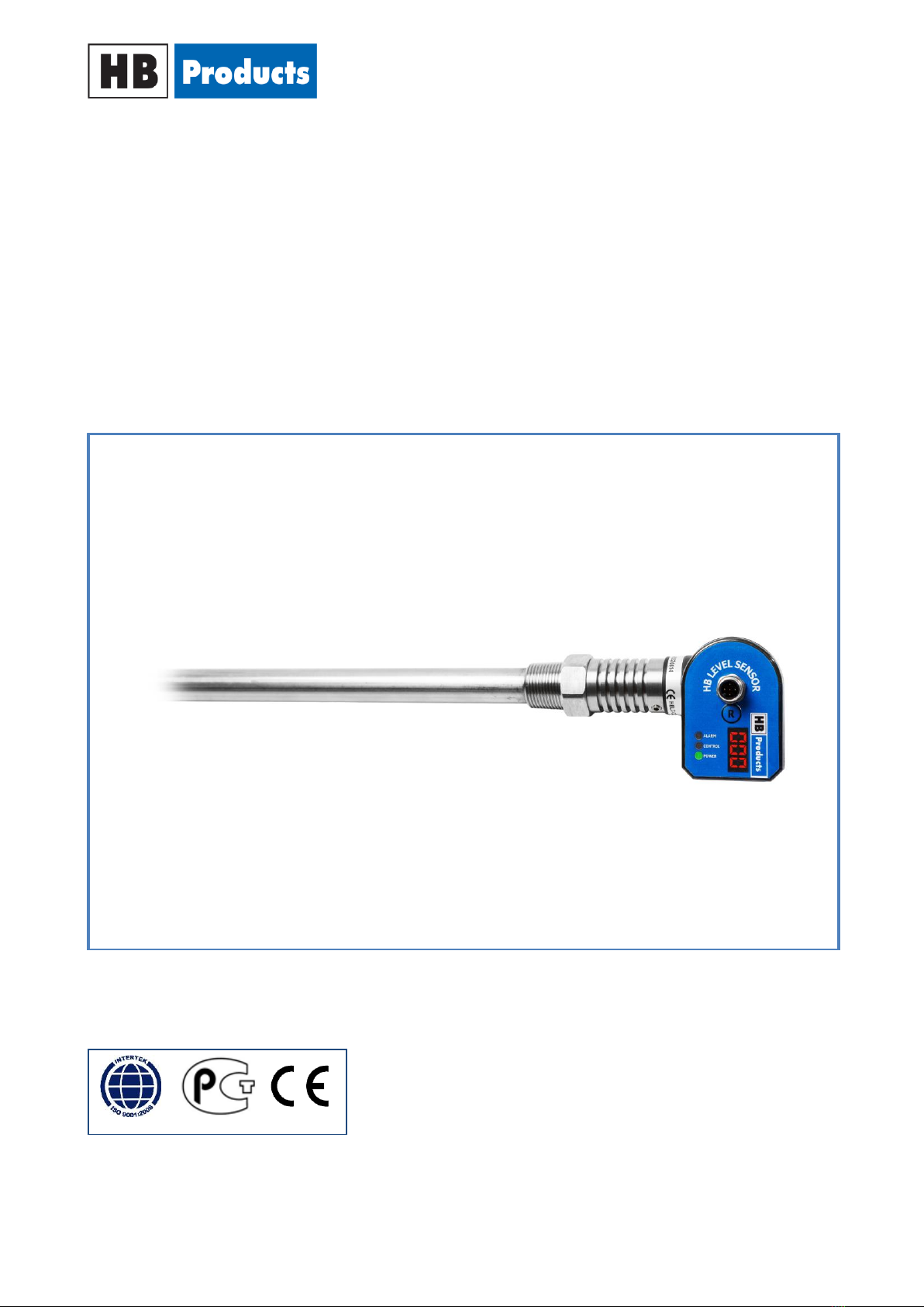
HBLC-XXX-x-x –LEVEL SENSOR
For analogue measurements of CO2 or HFC in refrigeration systems

Instruction manual –HBLC-xxx –Levelsensor (005-UK) 2 / 11
WE INCREASE
UPTIME AND EFFICIENCY
IN THE REFRIGERATION INDUSTRY
Table of contents
Safety Instructions...........................................................................3
Introduction..................................................................................... 4
Measurement Principle ...................................................................4
Design and Function ........................................................................4
Technical data..................................................................................5
Application Examples ......................................................................5
Installation Instructions...................................................................6
Power connection............................................................................6
Installation guide .............................................................................7
LED indication.................................................................................. 8
Alarm Reset & Calibration ...............................................................8
Installation of HB Configurations Tool.............................................9
PC Configuration..............................................................................9
Fault detection ................................................................................9
Sensor Repair.................................................................................10
Spare parts.....................................................................................11
Further information’s ....................................................................11
Instruction manual –HBLC-xxx –Levelsensor (005-UK) 3 / 11
WE INCREASE
UPTIME AND EFFICIENCY
IN THE REFRIGERATION INDUSTRY
Safety Instructions
CAUTION! Always read the instruction manual before commencing work! Heed all warnings to the letter!
Installation of the sensor requires technical knowledge of both refrigeration and electronics. Only qualified
personnel should work with the product. The technician must be aware of the consequences of an
improperly installed sensor, and must be committed to adhering to the applicable local legislation.
If changes are made to type-approved equipment, this type approval becomes void. The product's input
and output, as well as its accessories, may only be connected as shown in this guide. HB Products assumes
no responsibility for damages resulting from not adhering to the above.
Explanation of the symbol for safety instructions. In this guide, the symbol below is used to point out
important safety instructions for the user. It will always be found in the chapters where the information is
relevant. The safety instructions and the warnings in particular, must always be read and adhered to.
CAUTION! Refers to a possible limitation of functionality or risk in usage.
NOTE! Contains important information about the product and provides further tips.
The person responsible for operation must comply with all the legislative requirements with
regards to accident prevention, and take all necessary care to avoid damage to both people
and materials.
Intended use, conditions of use. The level sensor is designed for continuous measurement of liquid CO2 or
HFC in refrigeration systems. If the sensor is to be used for a different application and if the operation of
the product in this application is considered to be problematic, prior approval must be obtained from HB
Products.
Prevention of collateral damage Make sure that only qualified personnel work with the sensor and that all
necessary precautions are taken before attempting to make replacements or repairs, so as to avoid any
collateral damage.
Disposal instructions: The sensor is constructed so that the modules can easily be removed and sorted for
disposal.

Instruction manual –HBLC-xxx –Levelsensor (005-UK) 4 / 11
WE INCREASE
UPTIME AND EFFICIENCY
IN THE REFRIGERATION INDUSTRY
Introduction
HBLC-XXX is an intelligent sensor with a built-in
microprocessor. It is designed for continuous
level measurement of liquid CO2 or HFC
refrigerant in refrigeration systems.
The sensor emits a 4-20mA analogue signal,
which is proportional to the liquid level.
The construction of the sensor makes it suitable
for systems with pressure of up to 150 bar.
Measurement Principle
The sensor is a capacitive sensor. The capacitive measurement principle is based on the electrical
properties in the proximity of a capacitor. A capacitor is an electrical component that is capable of building
and sustaining an electrical charge.
A capacitor basically consists of two plates.
When a charge is applied to a plate, the other
plate will be charged with the opposite polarity
and retain the charge until it has been grounded.
The magnitude of the charge (the capacitance)
that can be generated depends, among other
things, on what is found between the plates.
The substance between the plates is referred to
as a dielectric.
Rather than the two plates, the sensor for level
measurement is shaped as a cylindrical rod.
When liquid covers the sensor, the measured
capacity is changed.
The conductivity of a material can vary depending
on temperature, chemical composition, and the
homogeneity of the material, and therefore it can
in some cases require a different factory
calibration.
HB Products sensors are calibrated so that they differentiate between conductive and non-conductive
liquids.
In refrigeration systems, oil, HFC and liquid CO2 are not regarded as conductive fluids, whereas refrigerants
such as ammonia and brine are regarded as conductive.
Design and Function
The sensor consists of a mechanical part and an electronic part. These are easily separated by loosening 2
grub screws or, for housings with mounting tabs, by pressing the sensor in towards the mechanical part and
turning the housing counter-clockwise until a wave washer pushes it from the mounted position. The
electronic part is designed in accordance with the IP65 waterproof rating and so as to resist vibrations.
The mechanical part is produced in AISI304/PTFE and tested to withstand high pressure.
The sensor is a very accurate analogue level transmitter for continuous measurement of liquid CO2 or HFC
on refrigerant plants. Additionally it may serve as high level switch, since the in-built switch function gives
an alarm signal at the 100% level.
Instruction manual –HBLC-xxx –Levelsensor (005-UK) 5 / 11
WE INCREASE
UPTIME AND EFFICIENCY
IN THE REFRIGERATION INDUSTRY
Technical data
Supply:
Supply: 24 V AC/DC ±10%*
Current draw: Max 50 mA
Plug: M12, 5 pins -
DIN 0627
Output:
Analogue output: 4-20 mA
Permitted load on potential
free contactless set 1A (24V DC)
Installation conditions:
Ambient temperature: -30…50°C
Refrigerant temperature: -55…+30°C
Max. operational pressure: 150 bar
Waterproof rating: IP65
Vibrations: IEC 68-2-6 (4g)
Authorisations:
EMC Emission: EN61000-3-2
EMC Immunity: EN61000-4-2
GOST R: No 0903044
Mechanical specifications:
Thread connection: ¾” NPT & BSPP
Materials - mechanical parts:AISI304/PTFE
Materials - electronic parts: Nylon 6 (PA)
Housing design: Front
Calibration & indication:
Calibration Press-button
LED indication: Green, yellow, and
red
Cable specification:
Supply cable, 5 meters: HBxC-M12/5
Cable size: 5 x 0,34 mm2
Cable glands: PG7 / M8
Plug type: Angle - 90°
Cable type: PVC-OB grey
Accessories:
Threaded 1” BSP adapter
with alu. gasket HBS/ADAP/8/2
Torque screwdriver: HBxC-Torque
for supply cable fixation (0,6Nm)
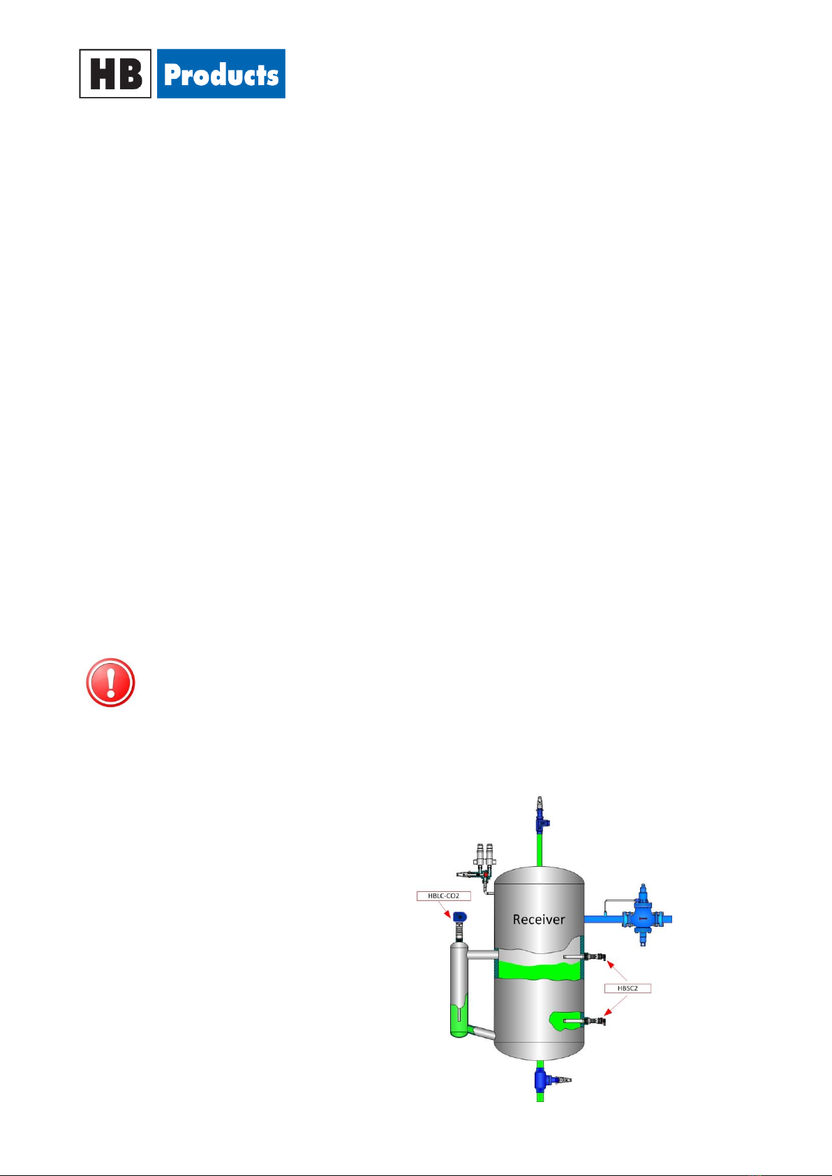
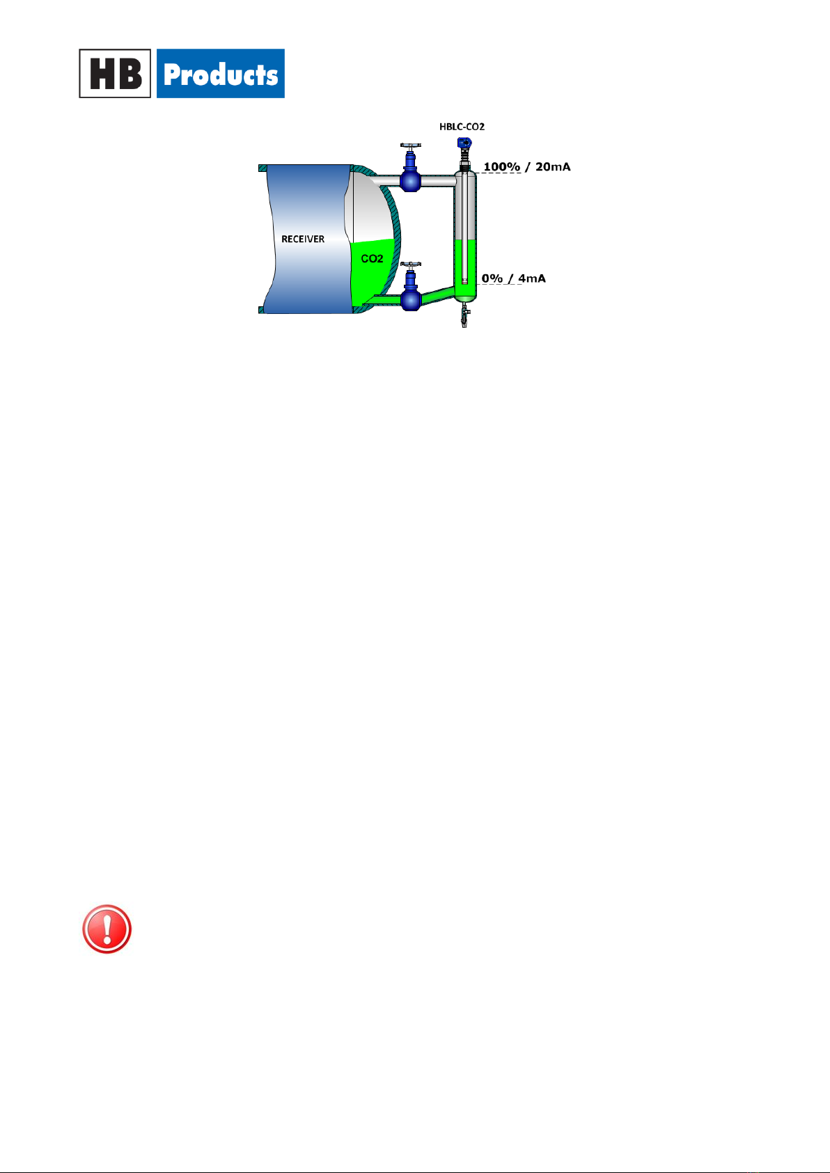
Application Examples
HBLC-xxx is designed for level measurement
of liquid CO2 or HFC in chillers, pump separators, coolers
and condensers. e.g.:
NOTE! All terminals are protected against improper termination with a supply voltage up to
40 V. If the supply voltage is greater than 40 V the electronics will be damaged.
Please note! Supply Voltage may differ from the data given in the manuals. Applicable will
always be that specified on the sensor label.
Instruction manual –HBLC-xxx –Levelsensor (005-UK) 6 / 11
WE INCREASE
UPTIME AND EFFICIENCY
IN THE REFRIGERATION INDUSTRY
Installation Instructions
The following applies to the design of the system:
1) It must be installed in a vertical position
2) The sensor should be installed in a stand pipe where the flow stream and turbulence are
minimised.
3) The sensor is installed and is supplied with a standard non-shielded cable.
If EMC is greater than described in EN 61326, a shielded cable must be used.
CAUTION! In case of welding work on the unit, please make sure that proper earthing is carried
out to avoid damaging the electronics.
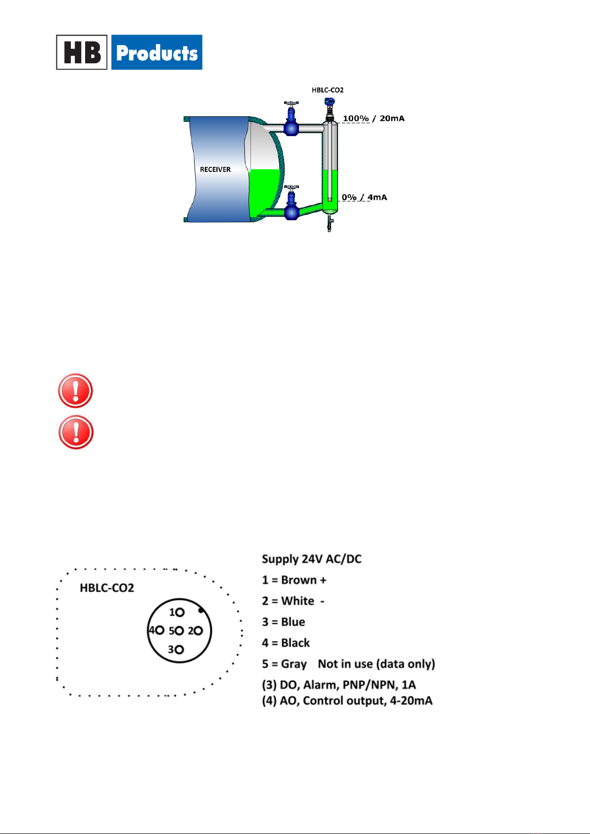
Power connection
The sensor must be wired with a 4 cord cable with a M12 connection plug
Colour codes in the below diagram are related to the cables offered by HB.
The supply voltage is limited to 24V AC/DC
NOTE! The sensor element must not touch the tank or other metal parts in its mounted
position. If so, the sensor will not give out a correct signal.
Instruction manual –HBLC-xxx –Levelsensor (005-UK) 7 / 11
WE INCREASE
UPTIME AND EFFICIENCY
IN THE REFRIGERATION INDUSTRY
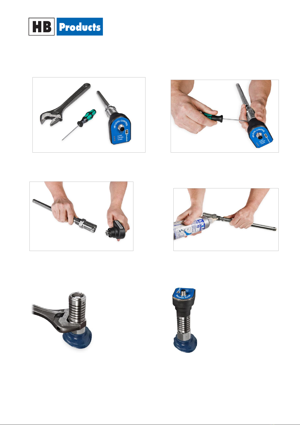
Installation guide
The sensor is installed in standpipe or directly in the container. Liquid gasket is applied to the thread.
To install the sensor, you must use a 2.5 mm Allen key,
shifting spanner, and gasket, depending on the type of
thread.
Loosen the two set screws that secure the electronic
part and the mechanical part.
Separate the electronic part from the mechanical part.
The hub of the two parts has been applied Molykote
ggrease type 111 silicone compound to minimize moisture
ppenetration. Do not wipe off the grease
Apply liquid gasket / Teflon to the conical thread.
Mount the electronic part in the container or standpipe
and tighten (80-150 Nm).
Mount the electronic part and tighten the two set
screws. Optionally apply Molykote grease 111
silicone compound before the two parts are
assembled.
Instruction manual –HBLC-xxx –Levelsensor (005-UK) 8 / 11
WE INCREASE
UPTIME AND EFFICIENCY
IN THE REFRIGERATION INDUSTRY
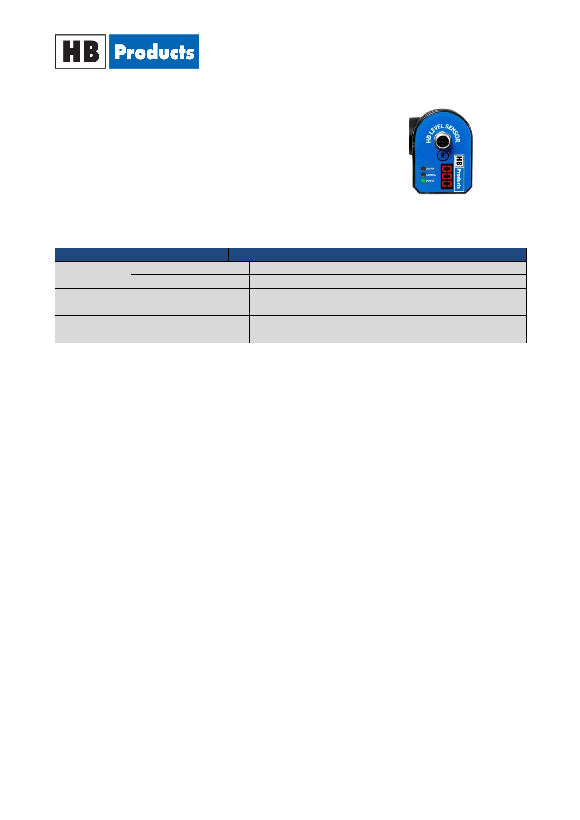
LED indication
LED indication:
1) Green LED indicates 24 V AC/DC supply (blinks during operation)
2) Yellow LED –in connection with calibration
3) Red LED indicates ALARM at 100%
LED Signal
ON/OFF/Frequency
Functionality
Green
ON
Supply
OFF
No supply
Yellow
ON
Activated during calibration
OFF
Normal operation
Red
ON
Alarm is activated after 10 seconds with 100% level
OFF
No alarm
Alarm Reset & Calibration
Alarm Reset: The alarm is reset by pressing "R" for 5 seconds.
The level transmitter comes pre-calibrated for CO2 or HFC and calibration is normally not required unless a
high measurement accuracy is required.
Calibration instructions:
0% or 100% for calibration can be carried out independent of each other. We recommend only calibrating
at 0% if a high degree of accuracy is desired.
Instruction for 0% calibration:
1) The sensors calibration function should be connected via the HB tool. See instruction for PC
connection and configurations parameters in separate manuals. Connect the supply cable
2) Disconnect the power cable
3) Empty the tank
4) Activate "R" for 5 seconds to activate calibration mode = Yellow LED is on (ON) during the 5 second
activation and turns off (OFF) when calibration mode is activated.
5) Activate "R" once = Yellow LED blinks once. Afterwards, the green LED blinks to confirm calibration.
Instruction manual –HBLC-xxx –Levelsensor (005-UK) 9 / 11
WE INCREASE
UPTIME AND EFFICIENCY
IN THE REFRIGERATION INDUSTRY
In case a smaller measurement area is desired, a recalibration can be performed.
6) Connect the PC Tool again and disconnect the calibration function in the tool.
7) Connect the power cable.
Instruction for 100% calibration:
1) The sensors calibration function should be connected via the HB tool. See instruction for PC
connection and configurations parameters in separate manuals. Connect the supply cable
2) The supply cable is connected
3) Fill the tank to 100%.
4) Activate "R" for 5 seconds to activate calibration mode = Yellow LED is on (ON) during the 5 second
activation and turns off (OFF) when calibration mode is activated.
5) Follow the instructions under "Configurations Instructions" regarding the installation of drivers in
the program.
6) Activate "R" twice = Yellow LED blinks twice. Afterwards, the green LED blinks to confirm
calibration.
7) Connect PC Tool again and disconnect the calibration function in tool.
8) Connect the power cable.
Installation of HB Configurations Tool
See separate manual.
PC Configuration
See separate manual.
Fault detection
General:
In case of fault, it is necessary to replace the electronic part only.
NOTE! Fault detection and/or changing the electronic function can be carried out without
releasing pressure from the system or disassembling the mechanical part of the sensor.
Instruction manual –HBLC-xxx –Levelsensor (005-UK) 10 / 11
WE INCREASE
UPTIME AND EFFICIENCY
IN THE REFRIGERATION INDUSTRY
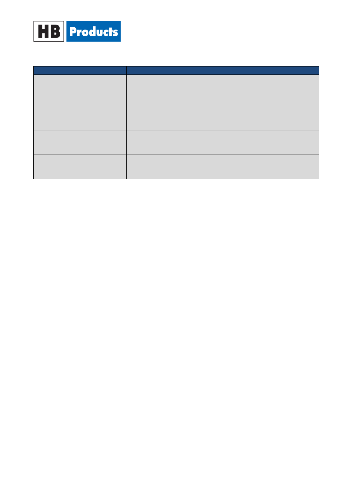
Fault detection
Fault
Reason
Correction of fault
No LED is lit / no function
No supply to the sensor or
defective cable/plug.
Check the power supply and the
supply cable.
No contact activation
There may be dirt between the
electronic housing and the
mechanical housing.
Separate the two parts and clean
the spring tip. Remember to apply
silicone grease to the spring tip so
as to avoid any problems with
moisture.
Delay in sensor activation
Can be caused by gas and
formation of foam in the system.
Check that the sensor is placed
optimally, so that gas and air are
avoided.
There is no correlation between
the output signal and the
measuring distance.
The sensor is not calibrated
correctly.
Perform calibration.
Sensor Repair
In case of faults with the sensor, it will typically be necessary to replace only the electronics.
Sensor electronics are fully encapsulated and can therefore not be repaired.
Complaint cases are handled by the HB products dealers/distributor.
Consideration must be given to the complaint procedures before returning the sensor.
Instruction manual –HBLC-xxx –Levelsensor (005-UK) 11 / 11
WE INCREASE
UPTIME AND EFFICIENCY
IN THE REFRIGERATION INDUSTRY
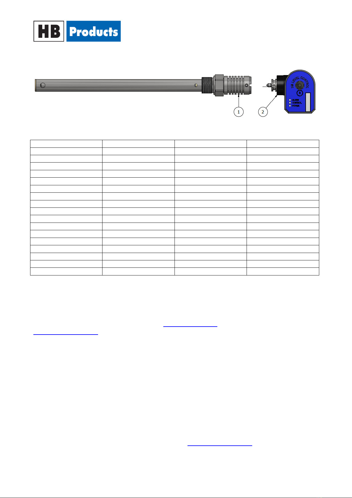
Spare parts
Position
Description
Specification
Part number
1
Mechanical parts
¾” NPT - 300 mm
HBLC-CO2-3-2-MEK
¾” NPT - 500 mm
HBLC-CO2-5-2-MEK
¾” NPT - 800 mm
HBLC-CO2-8-2-MEK
¾” NPT - 1000 mm
HBLC-CO2-10-2-MEK
¾” NPT - 1200 mm
HBLC-CO2-12-2-MEK
¾” NPT - 1400 mm
HBLC-CO2-14-2-MEK
¾” NPT - 1700 mm
HBLC-CO2-17-2-MEK
¾” NPT - 2500 mm
HBLC-CO2-25-2-MEK
¾” BSP - 300 mm
HBLC-CO2-3-6-MEK
¾” BSP - 500 mm
HBLC-CO2-5-6-MEK
¾” BSP - 800 mm
HBLC-CO2-8-6-MEK
¾” BSP - 1000 mm
HBLC-CO2-10-6-MEK
¾” BSP - 1200 mm
HBLC-CO2-12-6-MEK
¾” BSP - 1400 mm
HBLC-CO2-14-6-MEK
¾” BSP - 1700 mm
HBLC-CO2-17-6-MEK
¾” BSP - 2500 mm
HBLC-CO2-25-6-MEK
2
Electronic part
PC-programmable
HBLC-CO2-EL
Further information’s
For further information, please visit our website, www.hbproducts.dk or send an email to:
This manual suits for next models
17
Table of contents
Other HB Products Accessories manuals

HB Products
HB Products HBLT User manual

HB Products
HB Products HBCP User manual

HB Products
HB Products HBLT-WIRE User manual

HB Products
HB Products HBLC User manual

HB Products
HB Products HBLC User manual

HB Products
HB Products HBLT-A1 User manual

HB Products
HB Products HBPH-MK2 User manual

HB Products
HB Products HBOC User manual

HB Products
HB Products HBDF MK2 User manual

HB Products
HB Products HBDF-MK2 User manual


