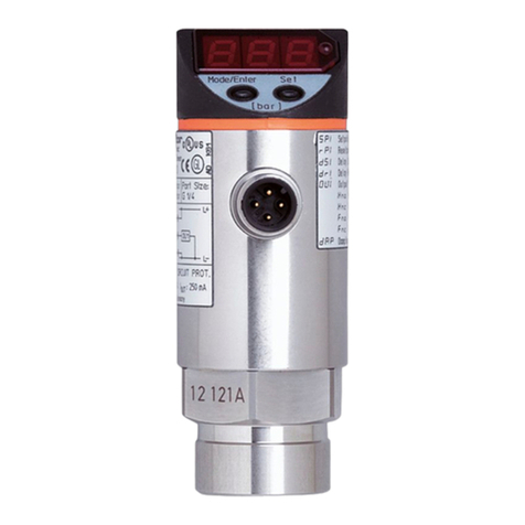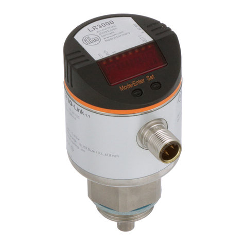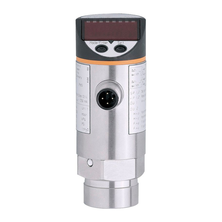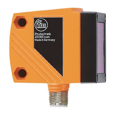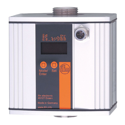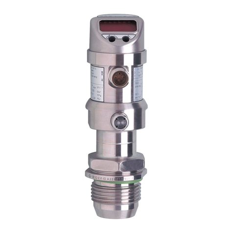
LR8009 Electronic level sensor
2
Contents
1 Preliminary note ............................................................. 4
1.1 Symbols used.......................................................... 4
2 Safety instructions............................................................ 5
3 Intended use................................................................ 6
3.1 Accessories............................................................ 6
3.2 Operation with single probe................................................ 7
3.3 Operation with coaxial probe............................................... 7
3.4 Application area ........................................................ 7
3.4.1 Restriction of the application area . . . . . . . . . . . . . . . . . . . . . . . . . . . . . . . . . . . . . . . 8
4 Function ................................................................... 9
4.1 Measuring principle...................................................... 9
4.2 Display functions........................................................ 9
4.3 Switching function....................................................... 9
4.4 Offset for indicating the real level in the tank. . . . . . . . . . . . . . . . . . . . . . . . . . . . . . . . . . . 10
4.5 Probes for different tank heights............................................ 10
4.6 Safe state............................................................. 10
4.7 Binary mode........................................................... 11
5 Installation.................................................................. 12
5.1 Device with single probe.................................................. 12
5.2 Device with coaxial probe................................................. 14
5.3 Installation of the probe................................................... 14
5.3.1 Installation of the rod................................................. 14
5.3.2 Installation of the coaxial pipe.......................................... 15
5.4 Shortening of the probe................................................... 15
5.4.1 Shortening of the rod and determination of its length L . . . . . . . . . . . . . . . . . . . . . . . 15
5.4.2 Shortening of the coaxial pipe.......................................... 15
5.4.3 Determination of the probe length L when coaxial probes are used . . . . . . . . . . . . . 16
5.5 Installation of the device with single probe . . . . . . . . . . . . . . . . . . . . . . . . . . . . . . . . . . . . 16
5.5.1 Installation in closed metal tanks (without flange plate) . . . . . . . . . . . . . . . . . . . . . . . 16
5.5.2 Installation in closed metal tanks (with flange plate) . . . . . . . . . . . . . . . . . . . . . . . . . 17
5.5.3 Installation in open tanks.............................................. 18
5.5.4 Installation in plastic tanks............................................. 18
5.6 Installation of the device with coaxial probe in the tank . . . . . . . . . . . . . . . . . . . . . . . . . . . 18
5.7 Alignment of the sensor housing............................................ 19
6 Electrical connection.......................................................... 20
7 Operating elements and display elements. . . . . . . . . . . . . . . . . . . . . . . . . . . . . . . . . . . . . . . . . . 21
8 Menu...................................................................... 22
8.1 Menu structure / switching mode (bin = OFF) . . . . . . . . . . . . . . . . . . . . . . . . . . . . . . . . . . 22
8.2 Menu structure / switching mode (bin = on). . . . . . . . . . . . . . . . . . . . . . . . . . . . . . . . . . . . 23
8.3 Explanation of the menu.................................................. 23
9 Parameter setting............................................................ 25
9.1 IO-Link ............................................................... 25
9.2 Parameter setting in general............................................... 25
9.3 Basic settings (on delivery)................................................ 27
9.3.1 Entering the probe length ............................................. 27
9.3.2 Setting to the medium................................................ 28
9.3.3 Entering the type of probe used . . . . . . . . . . . . . . . . . . . . . . . . . . . . . . . . . . . . . . . . 28
9.4 Setting ranges.......................................................... 28
9.5 Configuring the display................................................... 29
9.6 Offset setting........................................................... 29
9.7 Setting the output signals................................................. 29
9.7.1 Setting the output function............................................. 29
9.7.2 Setting the switching limits (hysteresis function) . . . . . . . . . . . . . . . . . . . . . . . . . . . . 29
9.7.3 Setting the switching limits (window function) . . . . . . . . . . . . . . . . . . . . . . . . . . . . . . 29
9.7.4 Setting the switch-off delay............................................ 30
9.7.5 Setting the switching logic for the outputs . . . . . . . . . . . . . . . . . . . . . . . . . . . . . . . . . 30


