SCM-PD-PLUS-Instructions
12V+ In Switched
1 2 3
ON
L ig h t 1
I N S T A L L J U M P E R
1 2 3 4 5 6
Light Position Setup (SW3)
1. (ON) Color Caster Installed
2. (ON) Color Caster Installed
3. (ON) Single Color Light Installed
4. (ON) Single Color Light Installed
5. (OFF) No Light Installed
6. (OFF) No Light Installed
ON
5 6 Mode Setup (SW2)
1. (ON) NetworkEnable
2. (OFF) Chase mode Enable
3. (OFF) Color Range
Power Switch Bypass
10V-30VDC
Indicator LED(-)
GND(-)
PD-PLUS
BOX
Push Button Switch
Optional Shadow-NET(H)
FUSE or
Circuit
Breaker
6 P o s i ti o n D i p S w i tc h :
S e t t o O N w h e n L i g h t i s
p r e s e n t
Located at connection to
power source
L ig h t 3
Push Button
Shadow-NET(L)
PWR(+)
L ig h t 2
GND
L ig h t 4
3 2
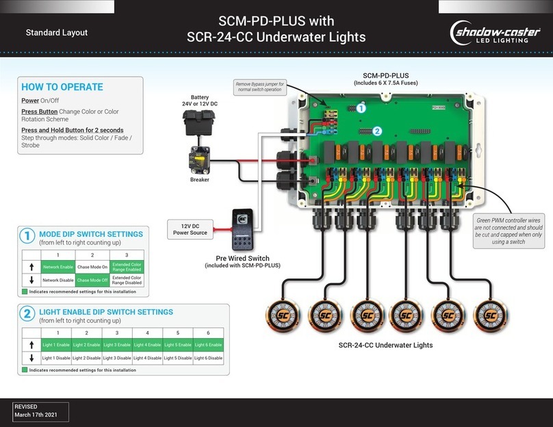
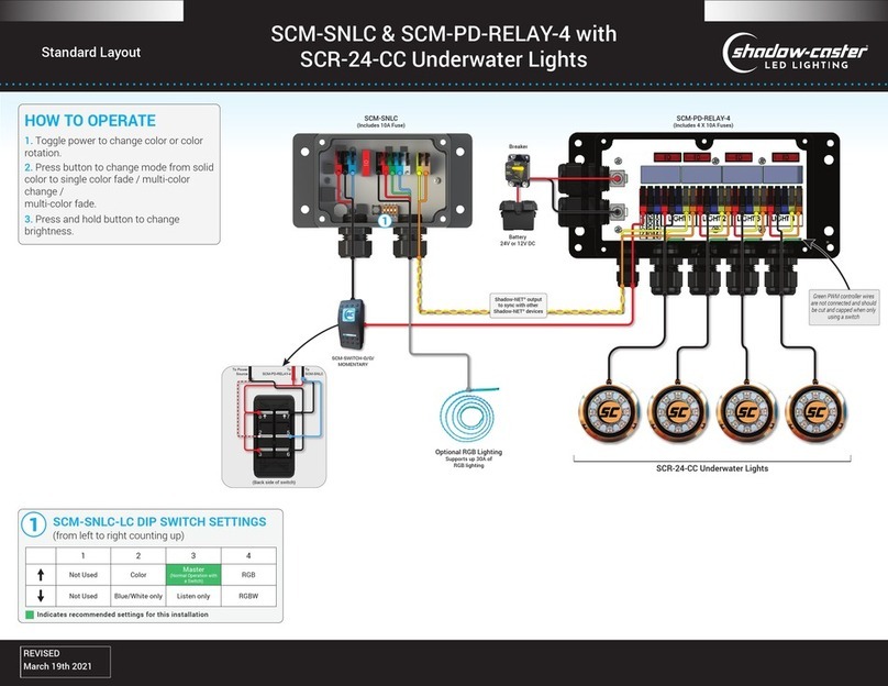
Diagram 2: Optional wiring Configuration for SCM-PD-PLUS shown with Color
Caster Lights on locations 1 and 2, Single Color Lights on locations 3 and 4. Note that
the jumper on the upper left corner of the board is installed for this power configuration.
2. Find a suitable mounting location:This box should be mounted in a dry
location, such as high in the bilge area, below the deck or inside the console. It is
preferred to not have the cable glands or the power wire connector facing up
where moisture will drain into the box.
3. Mount the Box:The box can be mounted with the included #8 stainless steel
pan head mounting screws.
4. Connect the Lights: Loosen the cable glands and route the cable through.
Strip the outer cable pack approximately 1.5 inches, and the ends of the wire back
approximately .25 of an inch. The connectors are color coded. Insert each wire
into the respective location and snap the connector down. Note that the green wire
from the Color-Casters is left unconnected. The blue connector is for the blue
wire on Shadow-Caster single color lights. Note that the lights should typically be
connected consecutively for implementation of chase modes. (I.e. light moves
from one light to the next in a linear pattern).
5. Connect Input Power:Route power into the box directly from a breaker, or
main fuse panel. See Diagram 1. The breaker and incoming wire should be sized
appropriately to the number and current draw of the lights being connected.
Pwr(+) and Gnd(-) are clearly marked on the printed circuit board. The power
connector will accept from 2awg to 20awg wire. For installations where it is
desired to switch the power directly, see Diagram 2. Installation of the blue
jumper on the upper left hand corner of the board will be necessary for this
configuration. See Picture 1.
