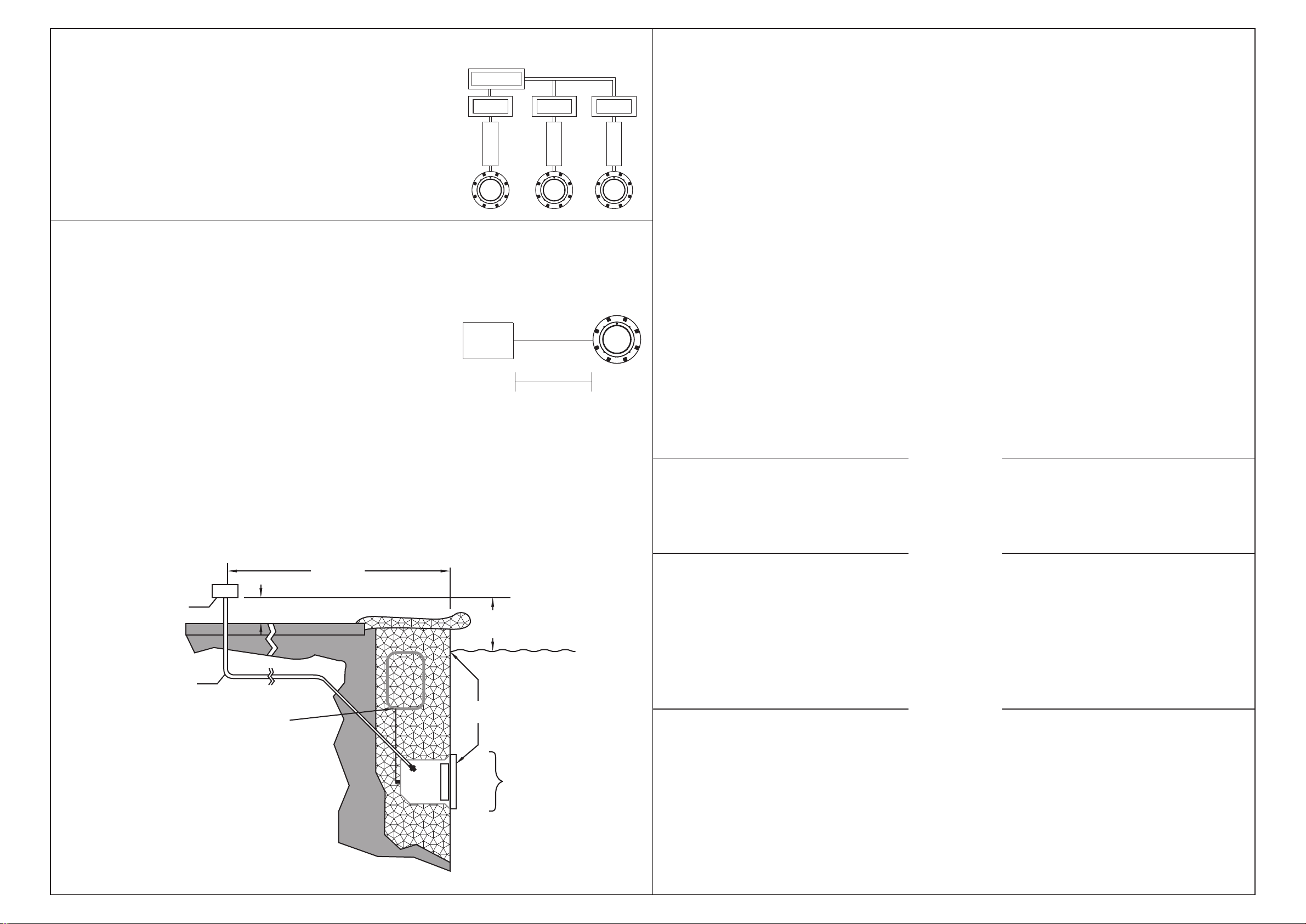
manuals.online logo
Brands
  1. Home
  2. •
  3. Brands
  4. •
  5. emaux
  6. •
  7. Underwater Lighting
  8. •
  9. emaux EL-S100S User manual

emaux EL-S100S User manual

EL-S100
UNDERWATER LIGHT OPERATING MANUAL
Keep this manual for future reference
REPLACEMENT PARTS
Model:EL-S100S / EL-S100P / EL-S100L
名 称
版 本 编 号
规 格
比 例
颜 色
产品负责人
更改日期
更改内容
版本 制图/设计
A
意万仕(中山)泳池设备有限公司
EMAUX ZhongShan)Swimming P o o l E q u i p m e n t Co., L t d(
审核 批准
80g印尼蓝
普通印刷
2018.05
1 : 1
420X297(mm)
EMLI18051002
PANTONE Process Black C
材 料
工 艺
日 期
EMAUX EL-S100 水灯 英文说明书
新文件
www.emauxgroup.com
EMLI18051002
4-4 4-1
G) Fill pool until the underwater light is completely submerged in water before operating the light for more than
60 seconds. Turn on main switch or circuit breaker, as well as the switch which specifically operates the
underwater light, to check for proper operation.
Use only the special pilot screw provided with this underwater light. This screw mounts and electrically grounds
the housing securely to the mounting ring and wet niche. Failure to use the screw provided could create an
electrical hazard which could result in death or serious injury to pool users, installers or others due to electrical
shock.
WARNING
Figure 4
1
PILOT SCREW SCREW OFF AND REPLACE LED PANEL
Item
Part No.
Product Description
Qty
1
3011058
∅33/16x9/8"Pilot Screw
1
2
440256151
Face Ring Assembly for EL-S100 Lights
1
3
440546196
Ultra-thin 99 LED panel 10W Warm White
1
440546195
Ultra-thin 99 LED panel 10W Cool White
1
440546197
Ultra-thin 99 LED panel 10W RGB
1
440546198
Ultra-thin 99 LED panel 10W Single Blue
1
4
03011354
M4*8 Round Head Screw
2
5
88047302
Stainless Steel Housing
1
6
88043502
Plastic Housing
1
2
3
4
5
6
13 14
Mode E: RGB Colour Sequence: Red>Green>Blue
Mode F: Four Colour Sequence: Red>Green>Blue>Purple
Auto Colour Change
1
3
5
7
9
11
2
4
6
8
10
12
White Green
Green+Blue
Red+Blue
Mode B: Green+Gradual Red
Blue
Red+Green
Mode C: Blue+Gradual Green
Mode A: Blue+ Gradual Red
Mode D: Blue+Gradual Red
Rapid Auto Colour Change
Only suitably qualified installers is allowed to carry out the installation of this product.
•
•
•
•
•
•
•
Avoid direct contact with electrical power.
Respect all regulations in effect for preventing accidents.
All units are required to be disconnected from the main electricity before any operation of maintenance.
Never handle with wet hands and feet.
This unit is design for use only when fully submerged in water, connecting with a safety transformer.
Never operate this Underwater Light for more than 1 minute unless it is totally submerged in water.
Be sure power is off before installing or removing LED plate. Allow LED plate to cool before replacing.
This product should be installed according to your local electrical installation ordinances and regulations.
Maximum Depth for Light installation at 1 meter.
o
Maximum Water Temperature Range for light operation 0 - 30 C
SPECIFICATION
A) Electrical Specification : 1) Voltage : AC12V 2) Frequency : 50/60Hz 3) Power : 10W
B) Colour change options(For RGB version only)
•
•
•
•
SAFETY WARNINGS
for type Z attachments
The external flexible cable or cord of this luminaire cannot be replaced;if the cord is damaged,the
luminaire shall be destroyed.
•
MAINTENANCE OF THE LIGHTS
1) Do not leave the lights “on” above water for longer than 1 minute.
2) Before switching on the lights, check whether the lights are fully submerged underwater and
the circuit boxes are running properly.
3) This unit does not need any kind of maintenance. If it is not working properly, please contact
EMAUX authorized dealer where you purchase the unit from.
4) Warranty will be voided if the Emaux Underwater Light was dismantled by unauthorized
personnel.
C) To remove light assembly, remove the special pilot screw at top of face ring, remove light assembly from
niche, and place assembly on deck.
D) Disassemble light fixture and remove LED panel.
E) Secure the face ring to the light fixture. Sealing screws must be tightened in the following manner to ensure a
proper seal.
F) Replace the light assembly into the niche and tighten the special pilot screw.
Figure 2
≤30m
Transformer
Light
Figure 1
ON/OFF Switch
Light
Transformer
Light
Master Switch
Light
ON/OFF Switch ON/OFF Switch
INSATALLATION OF THE UNDERWATER LIGHT
4-3
4-2
Transformer
Transformer
6) Fill the pool until the underwater light is completely submerged in water before operating the light for more
than 60 seconds. Turn on main switch or circuit breaker, as well as the switch which operates the underwater
light itself, to check for proper operation.
Never operate this Underwater Light for more than 60 seconds unless it is totally submerged in water. Without
total submersion, the light assembly will get extremely hot, which may result in serious injury to pool users,
installers, or bystanders, or in damage to property.
5) Replace the light assembly into niche and tighten special pilot screw.
Use only the special stainless steel pilot screw provided with Underwater Light. Failure to use the screw provided
could create an electrical hazard which could result in death or serious injury to pool users, installers or others
due to electrical shock.
Always disconnect power to the pool light at the circuit breaker before servicing the light. Failure to do so could
result in death or serious injury to installer, servicemen, pool users, or others due to electrical shock.
A) Turn off main electrical switch or circuit breaker, as well as the switch which operates the underwater light
itself.
B) You will need the following items :
A LED panel, refer to Table 1.
Replace a color panel of being needs. Failure to replace lamp with the same type of lamp will damage the
light assembly and may cause an electrical hazard resulting in death or serious injury to pool users, installers, or
others due to electrical shock, and may also cause damage to property.
WARNING
WARNING
REPLACING A LED PANEL ONLY
DANGER
A The electrician must complete preparatory steps before light fixture is installed; see Figure 1.
)
1 Ensure that the pool meets the requirements of the current National Electrical Code and all local codes and
ordinances. A licensed or certified electrician must install the electrical system to meet or exceed those
requirements before the underwater light is installed. Some of the requirements of the National Electrical
Code which the Pool's electrical system must meet are as follows.
a) The lighting circuit must have a Ground Fault Circuit Interrupter (GFCI), and must have an appropriately
rated circuit breaker
b) The Junction Box (or, for 12 volt models, the low voltage transformer) must be located at least 20CM above
water level, at least 10CM above ground level, and at least 120CM from the edge of the pool; see Figure 3.
c) The light fixture and all metal items within 152CM of the pool must be properly electrically bonded.
d) The wet niche must be properly installed so that the top edge of the underwater light's lens is at least 45.5
below the surface of the water in the pool; see Figure 3.
e) The wet niche must be properly electrically bonded and grounded via the No.8 AWG ground connector
located at the rear of the niche; see Figure 3.
NOTE: The pool or spa electrical system can be verified with a pool and Spa Electrical Qualification Test kit. The
electrical system inspection using this kit must be performed by trained and certified personnel.
2) To be certain that pool's electrical system meets all applicable requirements, the electrician should also
consult the local building department.
)
1) Feed cord through conduit to Junction Box, leaving at least 120CM of cord at the light fixture to coil around
the light; see Figure 1. This 120CM of cord around the light allows the light to be serviced after the pool is filled
with water.
2) Cut the cord at the Junction BOX, leaving at least 15CM of cord to make connections.
3) Strip 15CM of the outer cord jacket to expose the three insulated wires. Be careful not to damage the
insulation on the three (3) inner wires.
4) Connect all three (3) wires to the corresponding circuit wires in the Junction Box, and secure the Junction
Box cover in place.
B) Steps to perform after the electrical system requirements are met.
120CM MIN.
2.5 CM RIGID CONDUIT
#8 AWG GROUND CONNECTOR BONDED TO REBAR
TO GFCI. CIRCUIT
BREAKER AND
POWER SOURCE
CONCRETE MUST BE CUT BACK
AROUND NICHE TO ALLOW FOR
A COMPACTED PLASTER SEAL.
45.5CM MIN. FROM WATER LINE
TO TOP OF LENS
10CM MIN.
20CM MIN. JUNCTION BOX OR
LOW VOLTAGE TRANSFORMER
Figure 3
INSTALLATION NOTES
1) You should follow the procedures closely when installing the
light.
2) It is recommended to install a light every 20m , the approximate
exposure area of each unit.
3) The lights should be installed in the direction that they will not
shine directly into the house.
4) For training or competition pools, the lights must be installed on
the sides in order to prevent swimmers from seeing any glare.
5) Nothing should be placed on the poolside directly above the
lights for ease of future maintenance.
6) If the wires are connected inside the lights, you must seal the
connections with leak-proof tapes or products with the same
function.
7) The cables connecting the lights and the transformers must be
2
at least 6mm and the distance between them must not
exceed 30m (Figure 2); otherwise the lights will not function
properly.
2
C) Control
1) When the light is connected to the transformer
directly, the on/off switch controls the colour changes
(Associating a light with a transformer and an on/off
switch is recommended; If you want all the lights to
change colour at the same time, install a master
switch, Figure 1).
2) If applicable, when the light is connected to the
transformer and the transformer to the optional control
box, the control panel on the control box and its
remote control controls the colour changes (See the
Control Box Manual for details).

This manual suits for next models

2

Other emaux Underwater Lighting manuals

emaux UL-CP100 User manual

emaux

emaux UL-CP100 User manual

emaux GL10 User manual

emaux

emaux GL10 User manual

emaux ElumenX Series User manual

emaux

emaux ElumenX Series User manual

emaux EL-H200 User manual

emaux

emaux EL-H200 User manual

emaux Arr30 User manual

emaux

emaux Arr30 User manual

emaux NP300 Series User manual

emaux

emaux NP300 Series User manual

emaux P50 User manual

emaux

emaux P50 User manual

emaux E-Lumen X User manual

emaux

emaux E-Lumen X User manual

emaux P50 Instructions for use

emaux

emaux P50 Instructions for use

emaux EL-NP300 Series User manual

emaux

emaux EL-NP300 Series User manual

emaux NP300 Series User manual

emaux

emaux NP300 Series User manual

emaux UL-P300 Series User manual

emaux

emaux UL-P300 Series User manual

emaux NP300 Series User manual

emaux

emaux NP300 Series User manual

emaux LED-P100 series Manual

emaux

emaux LED-P100 series Manual

emaux E-Lumen X Series User manual

emaux

emaux E-Lumen X Series User manual

emaux UL-TP100 Series Manual

emaux

emaux UL-TP100 Series Manual

emaux LED-TP100 Series Manual

emaux

emaux LED-TP100 Series Manual

emaux E-Lumen Compact User manual

emaux

emaux E-Lumen Compact User manual

emaux UNDERWATER LIGHT Series User manual

emaux

emaux UNDERWATER LIGHT Series User manual

emaux E-Lumen-252 User manual

emaux

emaux E-Lumen-252 User manual

emaux LED-P10 User manual

emaux

emaux LED-P10 User manual

emaux UL-P100 Series Manual

emaux

emaux UL-P100 Series Manual

Popular Underwater Lighting manuals by other brands

Astral Pool JELLY-RGB Installation and maintenance manual

Astral Pool

Astral Pool JELLY-RGB Installation and maintenance manual

AMP Lighting HydraPro MR11 Installation & maintenance guide

AMP Lighting

AMP Lighting HydraPro MR11 Installation & maintenance guide

Keldan VIDEO 18XR 35000lm CRI 86 operating instructions

Keldan

Keldan VIDEO 18XR 35000lm CRI 86 operating instructions

DeepSea Power & Light SeaArc 2 400w HMI Operation manual

DeepSea Power & Light

DeepSea Power & Light SeaArc 2 400w HMI Operation manual

Halco J&J Electronics ColorSplash VU LPL-R1C-12... Installation and operation guide

Halco

Halco J&J Electronics ColorSplash VU LPL-R1C-12... Installation and operation guide

DeepSea Power & Light LED MULTI-SEALITE manual

DeepSea Power & Light

DeepSea Power & Light LED MULTI-SEALITE manual

lumishore THX 803 Installation and operating guide

lumishore

lumishore THX 803 Installation and operating guide

Shadow-Caster SCM-CC installation instructions

Shadow-Caster

Shadow-Caster SCM-CC installation instructions

Light & Motion SOLA owner's manual

Light & Motion

Light & Motion SOLA owner's manual

UNDERWATER LIGHTS LIMITED QT LED QTS-130-RGBW quick start guide

UNDERWATER LIGHTS LIMITED

UNDERWATER LIGHTS LIMITED QT LED QTS-130-RGBW quick start guide

Hayward 7016849 user guide

Hayward

Hayward 7016849 user guide

ASTEL MARINE PLAQUE Series operating instructions

ASTEL MARINE

ASTEL MARINE PLAQUE Series operating instructions

Aquant STANDARD Series Installation and maintenance manual

Aquant

Aquant STANDARD Series Installation and maintenance manual

Hayward UCL Niches owner's manual

Hayward

Hayward UCL Niches owner's manual

ccei Brio PK10R400 Technical instructions

ccei

ccei Brio PK10R400 Technical instructions

Hidrotermal HIDRO-SW200 Installation and maintenance manual

Hidrotermal

Hidrotermal HIDRO-SW200 Installation and maintenance manual

Polarion Abyss U Series manual

Polarion

Polarion Abyss U Series manual

Sea & Sea YS-03 SOLIS instruction manual

Sea & Sea

Sea & Sea YS-03 SOLIS instruction manual

manuals.online logo
manuals.online logoBrands
  • About & Mission
  • Contact us
  • Privacy Policy
  • Terms and Conditions

Copyright 2025 Manuals.Online. All Rights Reserved.