BANDIT
Content
1. Features
2. Fan configuration
3. Package contents
4. The case at a glance
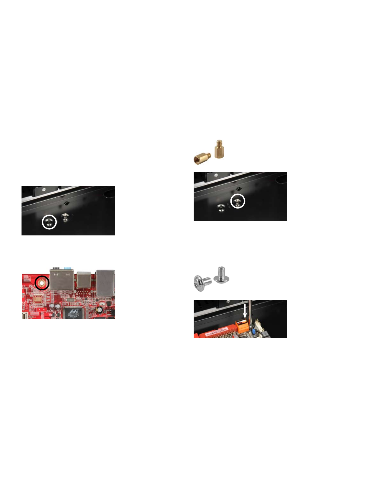
5. Installation of a mainboard
6. Installation of a PSU
7. Installation of a HDD
8. Installation of an optical device
9. Installation of an additional 3.5" device
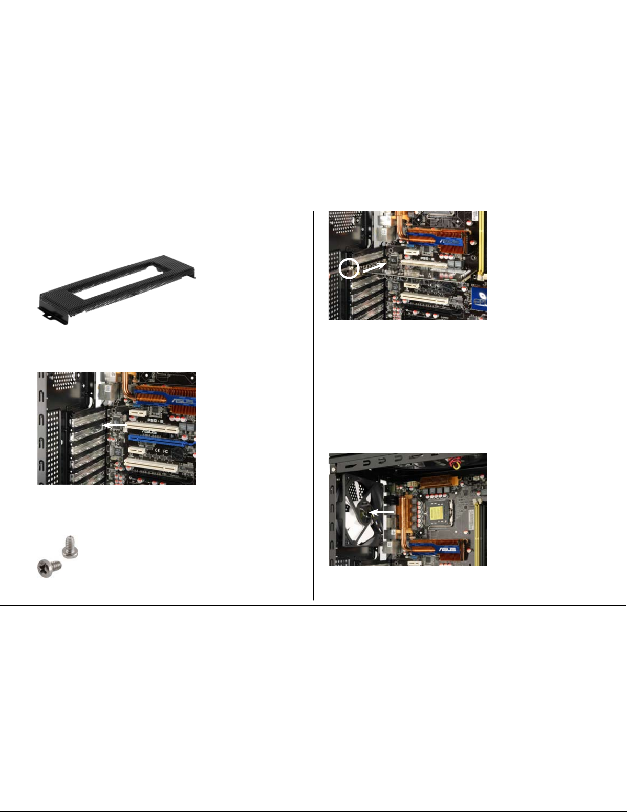
10. Installation of an add-on card
11. The pre-installed fans
12. Installation of additional fans / optimized airflow
13. The docking station for SATA HDDs in the case’s top panel
Dear customer!
Congratulations for purchasing one premium quality SHARKOON product.
For a long life time and to take full advantage of this product we recommend that
you read this manual completely.
Have a good time with our product!
SHARKOON Technologies
1. Features
• ATXcase
• 5x5.25"drivebays(external)
• 3x3.5"drivebays(internal)
• TopI/Owith2xUSB2.0,1xeSATA,1xheadphoneand1xmicrophone
connector,powerandresetbuttonaswellasLEDsforpowerandHDDactivity
• InstalledSATAdockingstationincasetop(for2.5"and3.5"HDDs)
• Pre-installedcardreaderwithUSB2.0connector(supportedcardformats:
SD/SDHC,MS,MMC,CF)
• 7slotsforadd-oncards
• Meshfrontpanelforoptimizedcooling
• Quickfastenersforopticaldrives
• Dimensions:485x485x200mm(LxHxW)
• Weight:~6.6kg
2. Fan configuration
Case front 1x120mmLEDfanwith3-pinand4-pinconnector
(pre-installed)
Side panel 2x140mmor2x120mmfans(optional)
Backsideofcase 1x120mmor1x80mmfan(optional)
Top panel 1x180mmLEDfan(pre-installed)
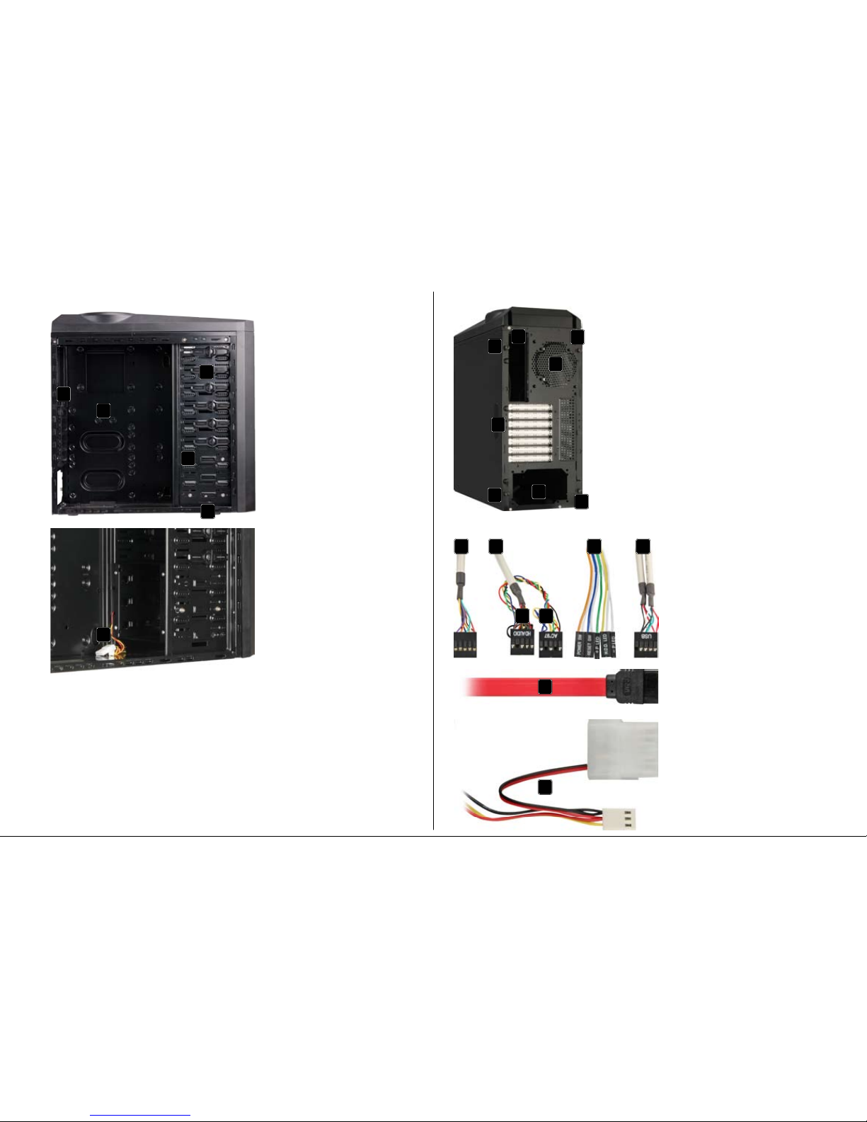
3. Package contents
• ATX-case“Bandit”(1x120mmLEDfaninthecasefront,
1x180mmLEDfaninthetoppanelandcardreaderpre-installed)
• Accessorykit:
Stand-offs for
mainboard
Screws for drive/
mainboard mounting
Screws for HDD/
PSU mounting
Screws with
coarse thread