Sharkoon MS140 User manual
Manual
MS140

MS140
Content
1. Features 3
2. Package content 4
3.The case at a glance 5
4. Installation notes 7
5. Removing the left HDD mounting plate 8
6. Installation of a mainboard 9
7. Installation of a PSU 11
8. Installation of a HDD 12
8.1 Into the lateral HDD mountings 12
8.2 Into the bottom panel 13
9. Installation of an optical device 14
10. Installation of a 3.5" device 16
11. Installation of an add-on card 17
12. Installation of additional fans / optimized airflow 18
Dear customer!
Congratulations for purchasing this premium quality SHARKOON product.
For a long life time and to take full advantage of this product we recommend you to read this manual completely.
Enjoy our product!
SHARKOONTechnologies
2
MS140
1. Features
• MicroATXcase
• 1x5.25"drivebay(external)
• 1x3.5"drivebay(external)
• Internalmountingareafor4x3.5“or6x2.5“HDDs
• 4slotsforadd-oncards
• FrontI/Owith1xUSB3.0,3xUSB2.0and2xaudio
• 1x140mmLEDfanpre-installed
• SupportsVGAcardsupto36cmlength
• Dimensions:420x175x368mm(LxWxH)
• Weight:~4kg
• Fanconguration:
Casefront 1x140mmLEDfan
Rearpanel 1x80mmor1x92mmfan(optional)
Casebottom 1x120mmfan(optional)
3

MS140
2. Package contents
• ATXcase„MS140“
• Screwkit:
Screwsformainboardand
drivemounting(3.5"and
5.25")
Mountingscrewsfor2.5"
HDDs/SSDs
ScrewsforPSUmounting ScrewsforHDDmounting
• Accessorykit:
Stand-offsformainboard Washers Cabletie(A)andspeaker(B)
Note:
If you are missing any of the items listed above, please contact our customer service immediately:
[email protected] (international).
4
A
B
MS140
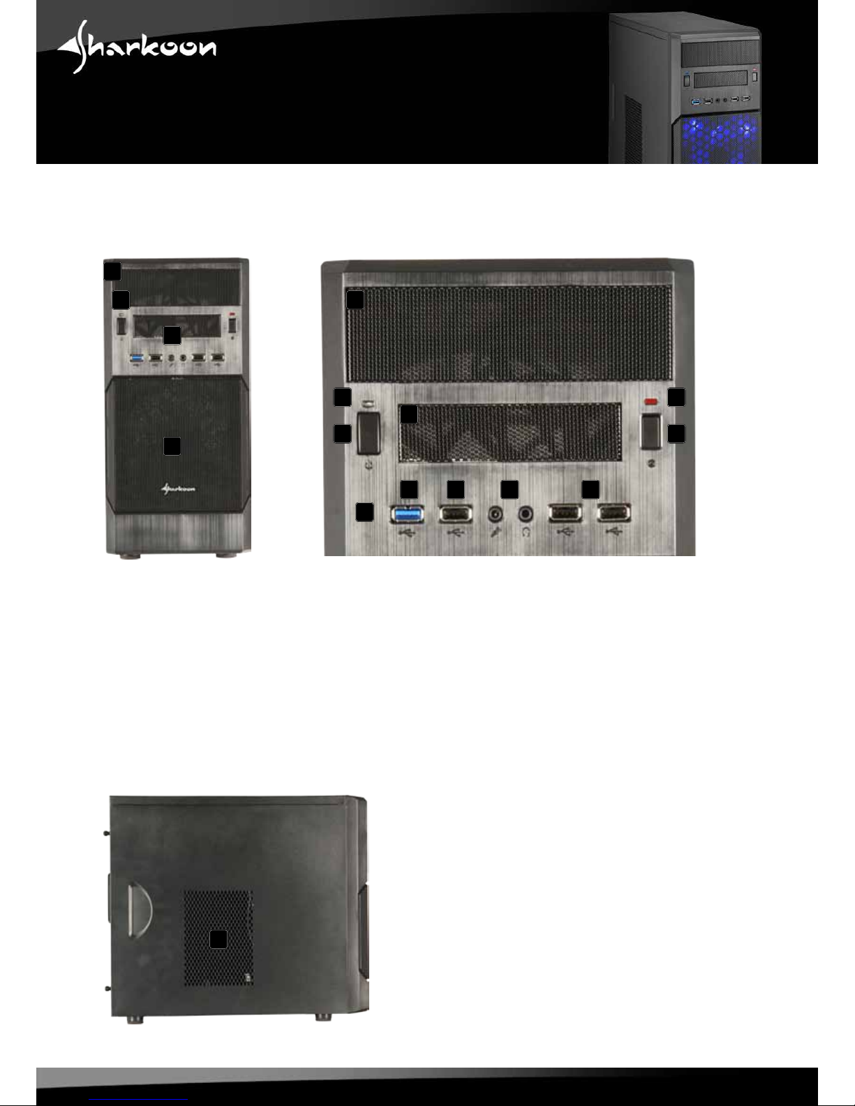
3.The case at a glance
Frontpanel
A – 5.25"drivebay
B – PowerLED
C – On/offbutton
D – FrontI/O:
a – 1xUSB3.0
b – 3xUSB2.0and
c – 2xaudio
E – 3.5"mountingbay
F – LEDforHDDactivity
G– Resetbutton
H – behindthemeshpanel:1x140mmLEDfan
Sidepanel(closed/left)
A–Airinlet
ab b
c
A
A
B
B
C
D
E
E
F
G
H
5
A

MS140
Sidepanel(opened/left)
A – 5.25"drivebay
B – 3.5"mountingbay
C – Attachmentsfor4x3.5"or
6x2.5"-HDDs/SSDs
D – Mainboardmountingpanel
Rearpanel
A – PSUbracket
B – OpeningforI/Oshield
C – Fanbracket(80or92mm)
D – Slotbezels
E – Thumbscrews
F – ConnectioncableforthefrontUSB3.0plug
6
A
A
B
B
C
D
C
D
E
E
E
E
F
MS140
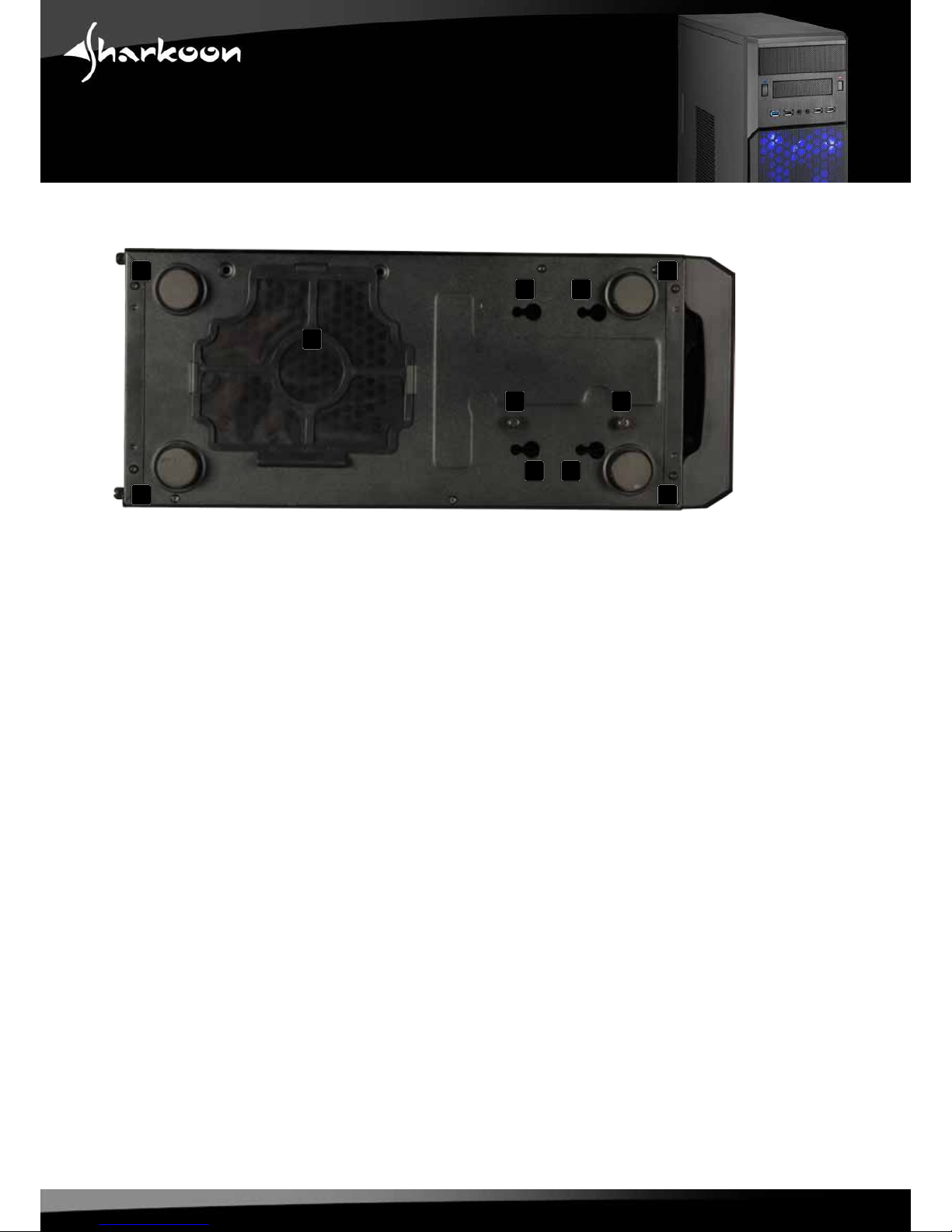
Bottompanel
A – Casefeet
B – Attachmentfor3.5“HDD
C – AttachmentscrewsforHDDmountingpanel
D – Bracketfor120mmfan
4. Installation notes
1.ForfurtherinformationonhowtoinstallthePCcomponents,alsorefertotheirrespectiveinstructions.
2.InordertoinstalllongVGAcards,itmightbenecessarytoremovetheleftHDDmountingpanel(see5.).
Tohavetheoptiontoinstallatleasttwo3.5“HDDs,thereisanadditionalHDDattachmentinthebottom
panelofthecase.
7
A A
AA
B B
BB
C C
D

MS140
Fig.1
1.Unscrewthethumbscrewsonthebacksideofthecaseandremovebothsidepanels.
2.UnscrewthethreeattachmentscrewsoftheHDDmountingpanelandremovethepanelfromthecase
(g.2a-c).
Fig.2a-c
5. Removing the HDD mounting plate
InordertoinstalllongVGAcards,andtoutilizethebottomHDDattachment,theleftHDDmountingpanel
(g.1)mustberemovedasfollows:
8

MS140
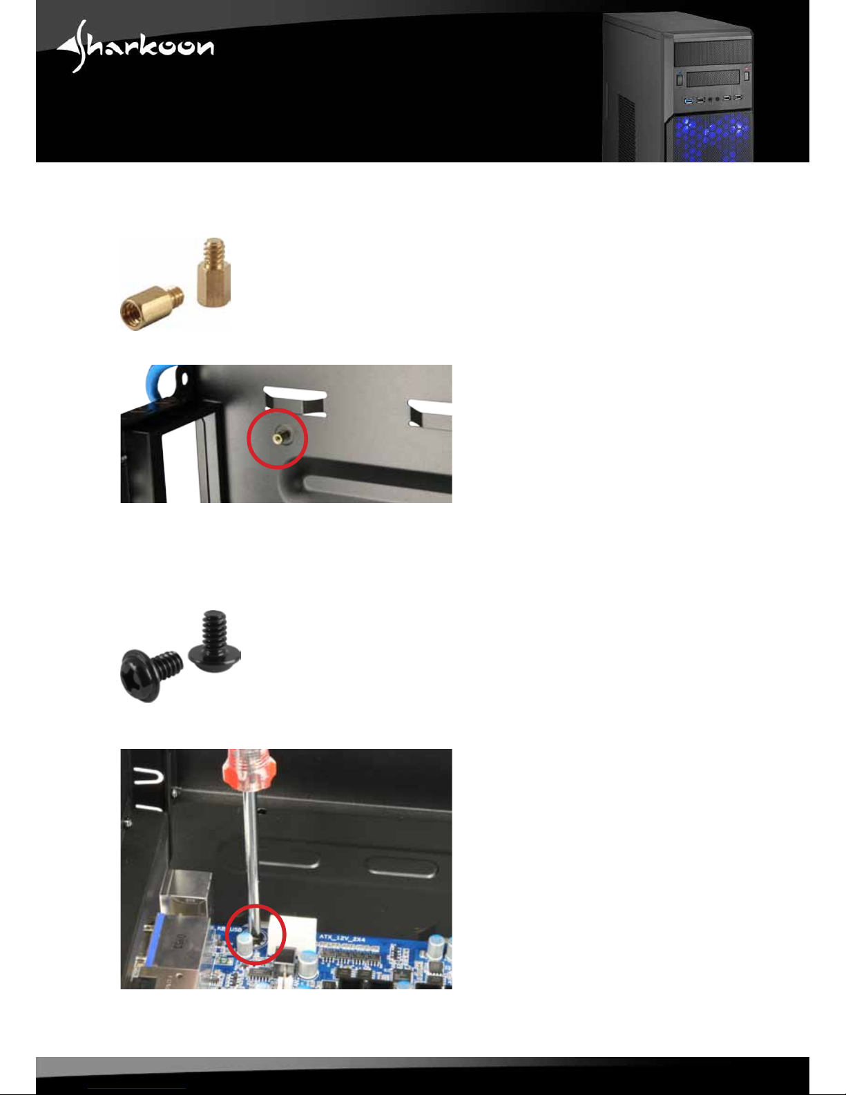
6. Installation of a mainboard
1.Unscrewthethumbscrewsonthebacksideofthecaseandremovetheleftsidepanel.Laydownthe
casesidewiseonanevensurface.
2.Themountingpanelofthemainboardinsidethecaseprovidesvariousmountingholestoxthe
standoffs(g.3).
Fig.3
Themainboardcontainsspecialscrewmounts(g.4).
Fig.4
Placethemainboardtothemountingpanel.Astandoffmustbescrewedintoeveryholeonthe
mountingpanelvisiblethroughthemainboard’sscrewopenings.
9
MS140
3.Removethemainboardandscrewthestandoffsintotherespectiveholesofthemountingpanel(g.5).
(Standoffs)
Fig.5
4.InserttheI/Oshield(deliveredwiththemainboard)intotheI/Oshieldopeningintherearpanelofthe
case.
5.Placethemainboardbackontothestandoffsandscrewthemainboardtothem(g.6).
(Screwsformainboardmounting)
Fig.6
10
Table of contents
Other Sharkoon Computer Accessories manuals

Sharkoon
Sharkoon 8-BAY RA ID STATION User manual

Sharkoon
Sharkoon VG6 Series User manual

Sharkoon
Sharkoon SCORPIO 1000 User manual

Sharkoon
Sharkoon VG7 User manual

Sharkoon
Sharkoon Skiller SGC1 User manual

Sharkoon
Sharkoon TG5 RGB User manual

Sharkoon
Sharkoon ELITE SHARK CA300T User manual

Sharkoon
Sharkoon RUSH POWER M User manual

Sharkoon
Sharkoon Bandit User manual

Sharkoon
Sharkoon VAYA User manual


