manuals.online logo
Brands
  1. Home
  2. •
  3. Brands
  4. •
  5. Sharp
  6. •
  7. All In One Printer
  8. •
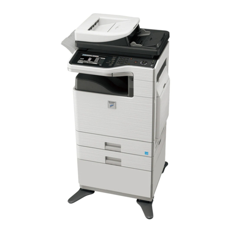
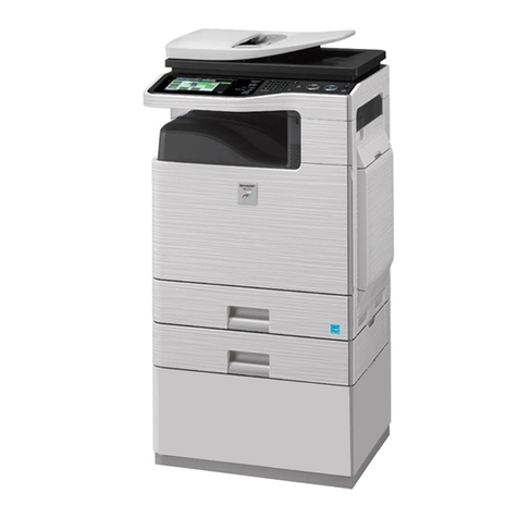
  9. Sharp MX-1810U User manual

Sharp MX-1810U User manual

Other manuals for MX-1810U

2

This manual suits for next models

6

Other Sharp All In One Printer manuals

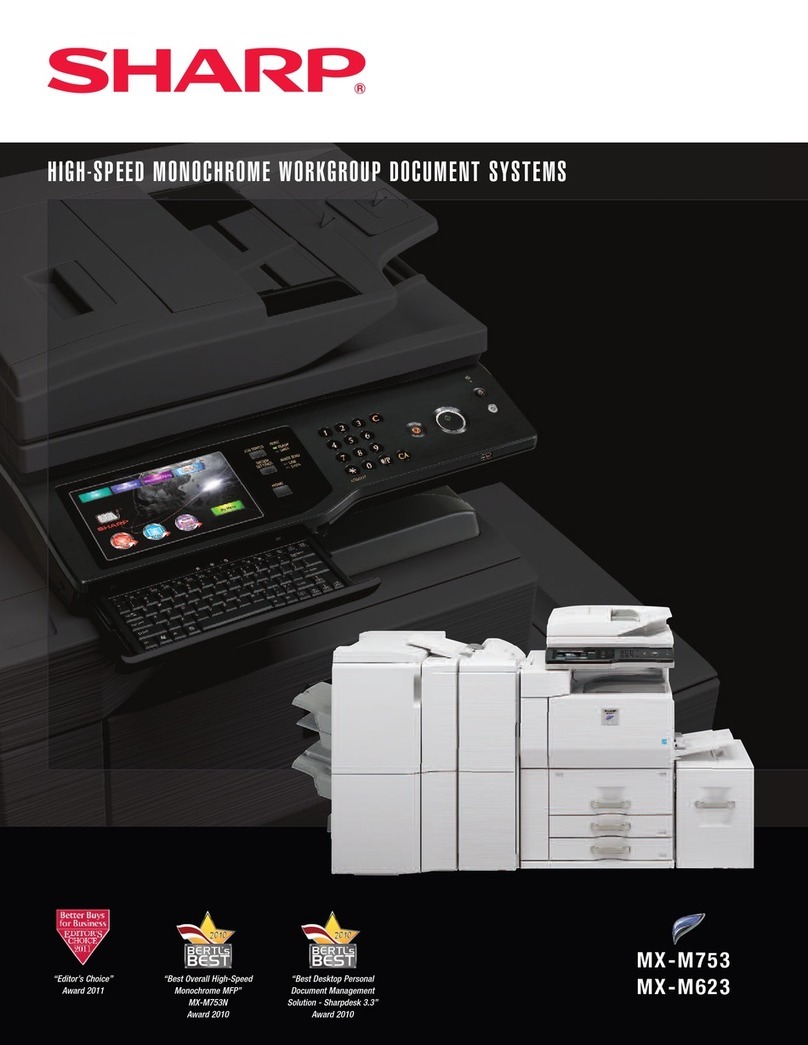
Sharp FO-3800M User manual

Sharp

Sharp FO-3800M User manual

Sharp AR-5516S Guide

Sharp

Sharp AR-5516S Guide

Sharp Advanced MXM365N User manual

Sharp

Sharp Advanced MXM365N User manual

Sharp MX-C303W Operating instructions

Sharp

Sharp MX-C303W Operating instructions

Sharp MX-7090N User manual

Sharp

Sharp MX-7090N User manual

Sharp MX-C312 Guide

Sharp

Sharp MX-C312 Guide

Sharp Advanced MXM365N User manual

Sharp

Sharp Advanced MXM365N User manual

Sharp MX-LCX3N User manual

Sharp

Sharp MX-LCX3N User manual

Sharp MX 5500N - Color Laser - Copier User manual

Sharp

Sharp MX 5500N - Color Laser - Copier User manual

Sharp MX-M1100 User manual

Sharp

Sharp MX-M1100 User manual

Sharp MX-7001 User manual

Sharp

Sharp MX-7001 User manual

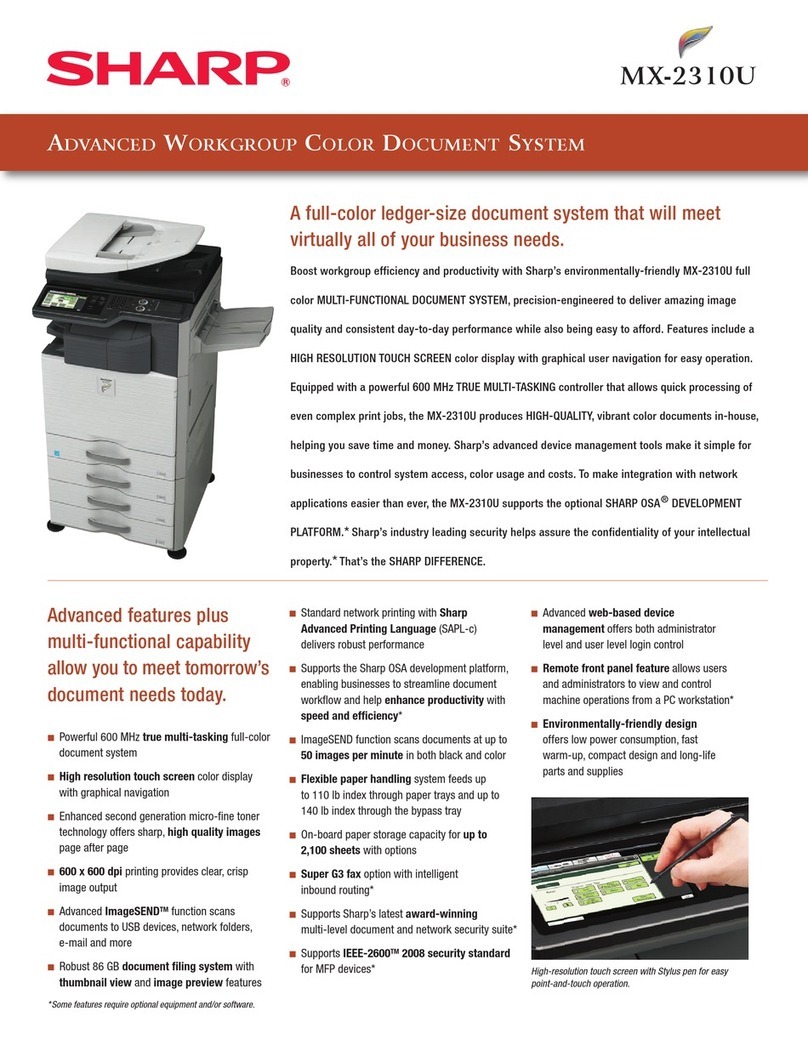
Sharp MX-2310U Guide

Sharp

Sharp MX-2310U Guide

Sharp AL-1552 User manual

Sharp

Sharp AL-1552 User manual

Sharp MX-4100N User manual

Sharp

Sharp MX-4100N User manual

Sharp MX-3110N User manual

Sharp

Sharp MX-3110N User manual

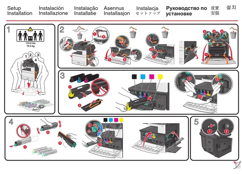
Sharp MX-6240N Installation instructions

Sharp

Sharp MX-6240N Installation instructions

Sharp MX-3640N User manual

Sharp

Sharp MX-3640N User manual

Sharp MX-C300P Guide

Sharp

Sharp MX-C300P Guide

Sharp MX-2314N Guide

Sharp

Sharp MX-2314N Guide

Sharp MX-3114N Operation Manual

Sharp

Sharp MX-3114N Operation Manual

Sharp MX-M2630 User manual

Sharp

Sharp MX-M2630 User manual

Sharp AL-2020 User manual

Sharp

Sharp AL-2020 User manual

Sharp AL-2051 User manual

Sharp

Sharp AL-2051 User manual

Sharp AR-208S User manual

Sharp

Sharp AR-208S User manual

Popular All In One Printer manuals by other brands

Brother MFC-J220 Basic user's guide

Brother

Brother MFC-J220 Basic user's guide

Brother MFC-8510DN Basic user's guide

Brother

Brother MFC-8510DN Basic user's guide

Ricoh Aficio FX200 Service training

Ricoh

Ricoh Aficio FX200 Service training

Olivetti d-Copia 16W Operation manual

Olivetti

Olivetti d-Copia 16W Operation manual

Konica Minolta bizhub C3850FS user guide

Konica Minolta

Konica Minolta bizhub C3850FS user guide

Konica Minolta bizhub 758 manual

Konica Minolta

Konica Minolta bizhub 758 manual

Lexmark MX310 Series Service manual

Lexmark

Lexmark MX310 Series Service manual

Ricoh Aficio 3224C operating instructions

Ricoh

Ricoh Aficio 3224C operating instructions

Sagem MF 3625 user manual

Sagem

Sagem MF 3625 user manual

Epson Epson Stylus NX530 quick guide

Epson

Epson Epson Stylus NX530 quick guide

Brother MFC9800 - MFC 9800 B/W Laser owner's manual

Brother

Brother MFC9800 - MFC 9800 B/W Laser owner's manual

Konica Minolta 7033 instruction manual

Konica Minolta

Konica Minolta 7033 instruction manual

Ricoh Aficio MP 161F operating instructions

Ricoh

Ricoh Aficio MP 161F operating instructions

Epson WorkForce WF-2510 Basic guide

Epson

Epson WorkForce WF-2510 Basic guide

Epson Stylus Scan 2000 Product information guide

Epson

Epson Stylus Scan 2000 Product information guide

Epson PictureMate Snap PM 240 Start here

Epson

Epson PictureMate Snap PM 240 Start here

Brother MFC-J430w user guide

Brother

Brother MFC-J430w user guide

Konica Minolta BIZHUB 558 Quick reference guide

Konica Minolta

Konica Minolta BIZHUB 558 Quick reference guide

manuals.online logo
manuals.online logoBrands
  • About & Mission
  • Contact us
  • Privacy Policy
  • Terms and Conditions

Copyright 2025 Manuals.Online. All Rights Reserved.

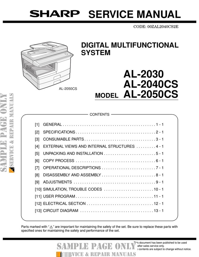
SERVICE MANUAL
Parts marked with " " are important for maintaining the safety of the set. Be sure to replace these parts with
specified ones for maintaining the safety and performance of the set.
SHARP CORPORATION This document has been published to be used
for after sales service only.
The contents are subject to change without notice.
NOTE FOR SERVICING
[1] PRODUCT OUTLINE . . . . . . . . . . . . . . . . . . . . . . . . . . . . . . . . . . . . . . . . . . . . . . . 1-1
[2] CONSUMABLE PARTS . . . . . . . . . . . . . . . . . . . . . . . . . . . . . . . . . . . . . . . . . . . . . 2-1
[3] EXTERNAL VIEW AND INTERNAL STRUCTURE . . . . . . . . . . . . . . . . . . . . . . . . 3-1
[4] ADJUSTMENTS AND SETTINGS . . . . . . . . . . . . . . . . . . . . . . . . . . . . . . . . . . . . . 4-1
[5] SIMULATION . . . . . . . . . . . . . . . . . . . . . . . . . . . . . . . . . . . . . . . . . . . . . . . . . . . . . 5-1
[6] TROUBLESHOOTING . . . . . . . . . . . . . . . . . . . . . . . . . . . . . . . . . . . . . . . . . . . . . . 6-1
[7] FIRMWARE UPDATE . . . . . . . . . . . . . . . . . . . . . . . . . . . . . . . . . . . . . . . . . . . . . . . 7-1
[8] MAINTENANCE . . . . . . . . . . . . . . . . . . . . . . . . . . . . . . . . . . . . . . . . . . . . . . . . . . . 8-1
[9] DISASSEMBLY AND ASSEMBLY . . . . . . . . . . . . . . . . . . . . . . . . . . . . . . . . . . . . . 9-1
[10] VARIOUS STORAGE DATA HANDLING . . . . . . . . . . . . . . . . . . . . . . . . . . . . . . . 10-1
[11] SERVICE WEB PAGE . . . . . . . . . . . . . . . . . . . . . . . . . . . . . . . . . . . . . . . . . . . . . 11-1
[12] OPERATIONAL DESCRIPTIONS. . . . . . . . . . . . . . . . . . . . . . . . . . . . . . . . . . . . . 12-1
[13] ELECTRICAL SECTION. . . . . . . . . . . . . . . . . . . . . . . . . . . . . . . . . . . . . . . . . . . . 13-1
[14] SPECIFICATIONS . . . . . . . . . . . . . . . . . . . . . . . . . . . . . . . . . . . . . . . . . . . . . . . . 14-1
[15] TOOL LIST . . . . . . . . . . . . . . . . . . . . . . . . . . . . . . . . . . . . . . . . . . . . . . . . . . . . . . 15-1
TopPage
CODE: 00ZMX3610/S5E
DIGITAL FULL COLOR
MULTIFUNCTIONAL SYSTEM
MX-1810U/2010U
MX-2310U/3111U
MX-2610N/3110N
MX-3610N
MODEL
CONTENTS
CONTENTS
NOTE FOR SERVICING
1. Precautions for servicing . . . . . . . . . . . . . . . . . . . . . . . . . i
2. Warning for servicing . . . . . . . . . . . . . . . . . . . . . . . . . . . . i
3. Note for installing site. . . . . . . . . . . . . . . . . . . . . . . . . . . . i
4. Note for handling PWB and electronic parts . . . . . . . . . .ii
5. Note for repairing/replacing the LSU . . . . . . . . . . . . . . . iii
6. Note for handling the drum unit, the transfer unit,
the developing unit. . . . . . . . . . . . . . . . . . . . . . . . . . . . . iii
7. Screw tightening torque . . . . . . . . . . . . . . . . . . . . . . . . . iii
[1] PRODUCT OUTLINE
1. System diagram . . . . . . . . . . . . . . . . . . . . . . . . . . . . . . 1-1
2. Option list . . . . . . . . . . . . . . . . . . . . . . . . . . . . . . . . . . . 1-5
[2] CONSUMABLE PARTS
1. Supply system table. . . . . . . . . . . . . . . . . . . . . . . . . . . 2-1
2. Maintenance parts list . . . . . . . . . . . . . . . . . . . . . . . . . 2-7
3. Definition of developer/drum life end . . . . . . . . . . . . . 2-19
4. Production number identification . . . . . . . . . . . . . . . . 2-21
5. Environmental conditions. . . . . . . . . . . . . . . . . . . . . . 2-21
[3] EXTERNAL VIEW AND INTERNAL STRUCTURE
1. External view . . . . . . . . . . . . . . . . . . . . . . . . . . . . . . . . 3-1
2. Internal structure . . . . . . . . . . . . . . . . . . . . . . . . . . . . . 3-4
3. I/F connectors . . . . . . . . . . . . . . . . . . . . . . . . . . . . . . . 3-5
4. Operation panel . . . . . . . . . . . . . . . . . . . . . . . . . . . . . . 3-6
5. Sensors and detectors . . . . . . . . . . . . . . . . . . . . . . . . . 3-8
6. Switches. . . . . . . . . . . . . . . . . . . . . . . . . . . . . . . . . . . 3-13
7. Clutches and solenoids . . . . . . . . . . . . . . . . . . . . . . . 3-15
8. Motors . . . . . . . . . . . . . . . . . . . . . . . . . . . . . . . . . . . . 3-18
9. Rollers . . . . . . . . . . . . . . . . . . . . . . . . . . . . . . . . . . . . 3-21
10. Lamps . . . . . . . . . . . . . . . . . . . . . . . . . . . . . . . . . . . . 3-26
11. Fans and filter . . . . . . . . . . . . . . . . . . . . . . . . . . . . . . 3-29
12. Gates . . . . . . . . . . . . . . . . . . . . . . . . . . . . . . . . . . . . . 3-31
13. Heater . . . . . . . . . . . . . . . . . . . . . . . . . . . . . . . . . . . . 3-33
14. PWB/Memory device . . . . . . . . . . . . . . . . . . . . . . . . . 3-34
15. Fuses and Thermostats . . . . . . . . . . . . . . . . . . . . . . . 3-40
16. Lock . . . . . . . . . . . . . . . . . . . . . . . . . . . . . . . . . . . . . . 3-43
[4] ADJUSTMENTS AND SETTINGS
1. General . . . . . . . . . . . . . . . . . . . . . . . . . . . . . . . . . . . . 4-1
2. Adjustment item list . . . . . . . . . . . . . . . . . . . . . . . . . . . 4-1
3. Details of adjustment . . . . . . . . . . . . . . . . . . . . . . . . . . 4-3
[5] SIMULATION
1. General and purpose . . . . . . . . . . . . . . . . . . . . . . . . . . 5-1
2. Starting the simulation . . . . . . . . . . . . . . . . . . . . . . . . . 5-1
3. List of simulation codes . . . . . . . . . . . . . . . . . . . . . . . . 5-4
4. Details of simulation. . . . . . . . . . . . . . . . . . . . . . . . . . 5-10
[6] TROUBLESHOOTING
1. Error code and troubleshooting . . . . . . . . . . . . . . . . . . 6-1
2. JAM and troubleshooting . . . . . . . . . . . . . . . . . . . . . . 6-38
3. Image send communication report code . . . . . . . . . . 6-49
4. Dial tone. . . . . . . . . . . . . . . . . . . . . . . . . . . . . . . . . . . 6-53
[7] FIRMWARE UPDATE
1. Outline . . . . . . . . . . . . . . . . . . . . . . . . . . . . . . . . . . . . . 7-1
2. Update procedure . . . . . . . . . . . . . . . . . . . . . . . . . . . . 7-1
[8] MAINTENANCE
1. Works necessary when executing
the maintenance. . . . . . . . . . . . . . . . . . . . . . . . . . . . . . 8-1
2. Display of maintenance execution timing. . . . . . . . . . . 8-2
3. Maintenance list . . . . . . . . . . . . . . . . . . . . . . . . . . . . . . 8-4
[9] DISASSEMBLY AND ASSEMBLY
1. Disassembly of Units . . . . . . . . . . . . . . . . . . . . . . . . . . 9-1
2. Disassembly and assembly of each unit . . . . . . . . . . 9-24
[10] VARIOUS STORAGE DATA HANDLING
1. HDD/SD card memory map . . . . . . . . . . . . . . . . . . . . 10-1
2. Necessary steps when replacing the PWB,
HDD and the SD Card . . . . . . . . . . . . . . . . . . . . . . . . 10-6
3. HDD/SD card SIM format operation. . . . . . . . . . . . . 10-12
4. Necessary works and notes for replacement
of the mirroring kit HDD . . . . . . . . . . . . . . . . . . . . . . 10-14
5. Note for installing and repairing the mirroring kit . . .10-17
[11] SERVICE WEB PAGE
1. General . . . . . . . . . . . . . . . . . . . . . . . . . . . . . . . . . . . 11-1
2. Details and operation procedures . . . . . . . . . . . . . . . 11-1
[12] OPERATIONAL DESCRIPTIONS
1. Operation panel section . . . . . . . . . . . . . . . . . . . . . . . 12-1
2. Scanner section . . . . . . . . . . . . . . . . . . . . . . . . . . . . . 12-6
3. Manual paper feed section. . . . . . . . . . . . . . . . . . . . . 12-8
4. Tray paper feed section . . . . . . . . . . . . . . . . . . . . . . 12-13
5. Paper registration section
(Paper transport section) . . . . . . . . . . . . . . . . . . . . . 12-19
6. Paper exit section. . . . . . . . . . . . . . . . . . . . . . . . . . . 12-23
7. ADU section . . . . . . . . . . . . . . . . . . . . . . . . . . . . . . . 12-29
8. LSU section . . . . . . . . . . . . . . . . . . . . . . . . . . . . . . . 12-34
9. Process section . . . . . . . . . . . . . . . . . . . . . . . . . . . . 12-41
10. Fusing section . . . . . . . . . . . . . . . . . . . . . . . . . . . . . 12-79
11. RSPF section . . . . . . . . . . . . . . . . . . . . . . . . . . . . . . 12-90
12. Fan and filter . . . . . . . . . . . . . . . . . . . . . . . . . . . . . . 12-96
13. Operations and specifications of counters . . . . . . . . 12-97
[13] ELECTRICAL SECTION
1. Block diagram . . . . . . . . . . . . . . . . . . . . . . . . . . . . . . 13-1
2. Power line diagram . . . . . . . . . . . . . . . . . . . . . . . . . 13-26
3. Actual wiring chart . . . . . . . . . . . . . . . . . . . . . . . . . . 13-32
4. Signal list . . . . . . . . . . . . . . . . . . . . . . . . . . . . . . . . . 13-68
[14] SPECIFICATIONS
1. 18cpm/20cpm machine . . . . . . . . . . . . . . . . . . . . . . . 14-1
2. 23cpm/31cpm(G) machine. . . . . . . . . . . . . . . . . . . . 14-10
3. 26cpm/36cpm/31cpm(A) machine . . . . . . . . . . . . . . 14-19
4. List of parts included in the package
of developer . . . . . . . . . . . . . . . . . . . . . . . . . . . . . . . 14-30
[15] TOOL LIST. . . . . . . . . . . . . . . . . . . . . . . . . . . . . . . . . . . . 15-1
Symbols in this manual
The lists of symbols used in this manual are shown below.
The meaning of each symbol described in the table must be understood for proper servicing.
1. Symbols used for notes and
cautions
2. Symbols used in the work
contents
Symbol Meaning
CAUTION Indicates a general
caution item.
HIGH TEMP Be careful of a high
temperature in the
fusing section.
HIGH VOLTAGE Be careful of an electric
shock where a high
voltage is applied such
as the high voltage
PWB, the main charger,
and the process section.
DANGER Indicates danger.
HANDLE WITH
CARE
Indicates a part which
requires special care for
handling such as the
HDD, and the LSU.
INHIBIT Indicates inhibit.
NO
ELECTROSTATIC
CHARGE
Be careful to keep away
from static electricity.
(PWB's and electric
parts)
NO DUST,
FINGER PRINT,
DIRT, SCRATCH
Be careful not to touch
directly, such as the
optical section, the
photoconductor, and the
DV roller.
Also be careful not to
scratch.
NO SCRATCH
NO LIGHT Be careful not to expose
to light, such as the
photoconductor, and the
test chart.
NO SOLVENT Be careful not to use a
solvent in cleaning, etc.
NO DISASSEMLE Do not disassemble.
Not serviceable.
Example CCD unit.
OK/GOOD Indicates a correct
procedure or result in an
adjustment, etc.
NO GOOD Indicates a wrong
procedure or result in an
adjustment, etc.
NOTE Indicates a note.
IMPORTANT Indicates an important
item.
REFER Indicates a reference
page, etc.
NEW Indicates a new
technology, a new
method, or a new item.
EXAMPLE Indicates a description
using an example.
Symbol Meaning (Work content)
Adhesion Indicates that a seal, etc.
is attached.
Adjustment Indicates an adjustment.
Measure a
dimension or a
size.
Indicates that a
dimension or a length is
measured.
Apply grease Indicates that grease is
to be applied.
Apply conductive
grease
Indicates conductive
grease is applied
Cleaning
(Dry)
Indicates clean with a
dry cloth.
Cleaning
(Wet)
Indicates clean with a
cloth dampened with
water.
Cleaning
(Alcohol)
Indicates clean with
alcohol.
Cleaning
(Blower)
Indicates cleaning is
done with a blower/
brush.
Symbol Meaning
3. Symbols used for kinds of parts
4. Symbols used for additional
descriptions
Cleaning
(Vacuum)
Indicates that cleaning is
performed with a
vacuum cleaner.
Cleaning
(Brush)
Indicates that cleaning is
performed with a brush.
Oil Indicates that oil is
applied to lubricate.
Apply powder. Indicates that setting
power is applied to the
photoconductor drum,
the transfer belt, etc.
Replace Indicates that a part is
replaced.
Check Indicates that a check
(replacement,
adjustment, cleaning) is
performed.
Cut Indicates that cutting is
performed.
Loosen Indicates that a screw is
loosened.
Connect Indicates that a
connector is connected.
Disconnect Indicates that a
connector is
disconnected.
Remove a
harness.
Indicates that a harness
is unsecured.
Attach a harness. Indicates that a harness
is secured.
Remove a clamp.
Attach a clamp.
Release a hook. Indicates that a hook is
released.
Fix a hook. Indicates that a hook is
fixed.
Disengage the
pawl.
Symbol Meaning (Work content)
Engage the pawl.
Screw lock Indicates that a screw is
secured with adhesive.
Unlock
Turn OFF the
power.
Disconnect the
power plug.
Symbol Meaning (Kinds of parts)
Maintenance
part
Indicates a part which is
replaced in a maintenance
procedure.
Consumable
part
Indicates a consumable
part such as a
photoconductor,
developer, a transfer belt,
etc.
Waste part Indicates a waste part
which is consumed but
excluded from the above
consumable parts. (A
roller, a seal, etc.)
Unit part Indicates a part which is
designated as a unit.
Included part Indicates a part which is
included in the package
Symbol Meaning
View from the
top
Indicates from which
angle the drawing is
viewed.
View from the
bottom
View from the
front
View from the
back
Symbol Meaning (Work content)
MX-3610N NOTE FOR SERVICING - i
MX-3610N Service Manual
NOTE FOR SERVICING
1. Precautions for servicing
• When servicing, disconnect the power plug, the printer cable, the
network cable, and the telephone line from the machine, except
when performing the communication test, etc.
It may cause an injury or an electric shock.
• There is a high temperature area inside the machine. Use
extreme care when servicing.
It may cause a burn.
• There is a high voltage section inside the machine which may
cause an electric shock. Be careful when servicing.
• Do not disassemble the laser unit. Do not insert a reflective
material such as a screwdriver in the laser beam path.
It may damage eyes by reflection of laser beams.
• When servicing with the machine operating, be careful not to
squeeze you hands by the chain, the belt, the gear, and other
driving sections.
• Do not leave the machine with the cabinet disassembled.
Do not allow any person other than a serviceman to touch inside
the machine. It may cause an electric shock, a burn, or an injury.
• When servicing, do not breathe toner, developer, and ink exces-
sively. Do not get them in the eyes.
If toner, developer, or ink enters your eyes, wash it away with
water immediately, and consult a doctor if necessary.
• The machine has got sharp edges inside. Be careful not to dam-
age fingers when servicing.
• Do not throw toner or a toner cartridge in a fire. Otherwise, toner
may ignite and burn you.
• When replacing a lithium battery on a PWB, only use the speci-
fied replacement battery.
If a battery of different specification is used, it may cause a
machine malfunction or breakdown.
• When carrying a unit with PWB or electronic parts installed to it,
be sure to put it in an anti-static-electricity bag.
It may otherwise cause a machine breakdown or malfunction.
2. Warning for servicing
• Be sure to connect the power cord only to a power outlet that
meets the specified voltage and current requirements.
Avoid complex wiring, which may lead to a fire or an electric
shock.
It may cause a fire or an electric shock.
• If there is any abnormality such as a smoke or an abnormal
smell, interrupt the job and disconnect the power plug.
It may cause a fire or an electric shock.
• Be sure to connect the grounding wire. If an electric leakage
occurs without grounding, a fire or an electric shock may result.
To protect the machine and the power unit from lightening,
grounding must be made.
• When connecting the grounding wire, never connect it to the fol-
lowing points.
Gas tube
Lightning conductor
A water pipe or a water faucet, which is not recognized as a
grounding object by the authorities.
Grounding wire for telephone line
It may cause an explosion, a fire or an electric shock.
• Do not damage, break, or stress the power cord.
Do not put heavy objects on the power cable. Do not stress, forc-
ibly bend, or pull the power cord.
It may cause a fire or an electric shock.
• Keep the power cable away from a heat source.
Do not insert the power plug with dust on it into a power outlet.
It may cause a fire or an electric shock.
• Do not place liquids or foreign metallic objects inside the
machine.
It may cause a fire or an electric shock.
• Do not touch the power cord, insert the phone jack, operate the
machine, or perform service on the machine with wet or oily
hands.
It may cause an electric shock.
3. Note for installing site
Do not install the machine at the following sites.
•Place of high temperature, high humidity, low temperature,
low humidity, place under an extreme change in temperature
and humidity.
Paper may get damp and form condensation inside the machine,
causing paper jam or copy dirt.
For operating and storing conditions, refer to the specifications
described later.
•Place of extreme vibrations
It may cause a breakdown.
•Poorly ventilated place
An electrostatic type copier will produce ozone.
The quantity of ozone produced is designed to a low level so as
not to affect human bodies. However, continuous use of such a
machine may produce an ozone smell. Install the machine in a
well ventilated place.
CAUTION
DOUBLE POLE/NEUTRAL FUSING
(200V series only)
MX-3610N NOTE FOR SERVICING - ii
•Place of direct sunlight.
Plastic parts and ink may be deformed, discolored, or may
undergo qualitative change.
It may cause a breakdown or output quality problems.
•Place which is full of organic gases such as ammonium
The organic photo-conductor (OPC) drum used in the machine
may undergo qualitative change due to organic gases such as
ammonium.
Installation of this machine near a diazo-type copier and blue
print machine may result in poor quality output.
•Place of much dust
When dust or contaminants enters the machine, it may cause a
breakdown or poor quality output.
•Place near a wall
The machine will require ventilation.
If ventilation is not proper, poor output or machine failure may
result.
•Unstable or irregular surface
If the machine is dropped or tips over, it may cause injury or
machine malfunction.
Use an optional desk or an exclusive-use desk.
When using the optional desk, be sure to fix the adjuster and lock
the casters.
4. Note for handling PWB and electronic
parts
When handling the PWB and the electronic parts, be sure to
observe the following precautions in order to prevent against dam-
age by static electricity.
• When in transit or storing, put the parts in an anti-static bag or an
anti-static case and do not touch them with bare hands.
• When and after removing the parts from an anti-static bag (case),
use an earth band as shown below:
• Put an earth band to your arm, and connect it to the machine.
• When repairing or replacing an electronic part, perform the
procedure on an anti-static mat.
11-13/16"
(30cm)
11-13/16"
(30cm)
17-23/32"
(45cm)
MX-3610N NOTE FOR SERVICING - iii
5. Note for repairing/replacing the LSU
When repairing or replacing, be sure to observe the following
items.
• When repairing or replacing the LSU, be sure to disconnect the
power plug from the power outlet.
• When repairing or replacing the LSU, follow the procedures
described in this Service Manual.
• When checking the operations after repairing the LSU, keep all
the parts including the cover installed and perform the operation
check.
• Do not modify the LSU.
• When visually checking the inside of the machine for the opera-
tion check, be careful not to allow laser beams to enter the eyes.
If the above precaution is neglected or the LSU is modified, ones
safety may be at risk.
6. Note for handling the drum unit, the
transfer unit, the developing unit
When handling the OPC drum unit, the transfer unit, and the devel-
oping unit, strictly observe the following items.
If these items are neglected, a trouble may be generated in the
copy and print image quality.
Drum unit
• Avoid working at a place with strong lights.
• Do not expose the OPC drum to lights including interior lights for
a long time.
• When the OPC drum is removed from the machine, cover it with
light blocking material. (When using paper, use about 10 sheets
of paper to cover it.)
• Be careful not to attach fingerprints, oil, grease, or other foreign
material on the OPC drum surface.
Transfer unit
• Be careful not to leave fingerprints, oil, grease, or other foreign
material on the transfer roller, primary transfer belt, and the sec-
ondary transfer belt.
Developing unit
• Be careful not to leave fingerprints, oil, grease, or other foreign
material on the developing unit.
7. Screw tightening torque
The screws used in this machine are largely classified into three
types.
These types are classified according to the shape of the screw
grooves and use positions.
The table below shows the types of the screws and the tightening
torques depending on the use position.
When tightening the screws for repair or maintenance, refer to the
table.
However, for the other conditions of tightening screws than speci-
fied on this table, or under special circumstances, the details are
described on the separate page. Refer to the descriptions on such
an exception.
Especially for the screw fixing positions where there is an electrode
or a current flows, use enough care to tighten securely to avoid
loosening.
Screw kinds and tightening torques
Normal screws, set screws (including step screws)
Tapping screws (for iron)
Tapping screw (for plastic)
Screw
diameter
Material to be
fixed
Tightening
torque
(Nm)
Tightening
torque
(kgfcm)
Tightening
torque
(lbft)
M2.6 Steel plate 0.8 - 1.0 8 - 10 0.6 - 0.7
M3 Steel plate 1.0 - 1.2 10 - 12 0.7 - 0.9
M4 Steel plate 1.6 - 1.8 16 - 18 1.2 - 1.3
Screw
diameter
Material to be
fixed
Tightening
torque
(Nm)
Tightening
torque
(kgfcm)
Tightening
torque
(lbft)
M3 Steel plate
(Plate thickness
0.8mm or above)
1.0 - 1.2 10 - 12 0.7 - 0.9
M4 Steel plate
(Plate thickness
0.8mm or above)
1.6 - 1.8 16 - 18 1.2 - 1.3
M3 Steel plate
(Plate thickness
less than 0.8mm)
0.6 - 0.8 6 - 8 0.4 - 0.6
M4 Steel plate
(Plate thickness
less than 0.8mm)
1.2 - 1.4 12 - 14 0.9 - 1.0
Screw
diameter
Material to be
fixed
Tightening
torque
(Nm)
Tightening
torque
(kgfcm)
Tightening
torque
(lbft)
M3 Plastic resin 0.6 - 0.8 6 - 8 0.4 - 0.6
M4 Plastic resin 1.0 - 1.2 10 - 12 0.7 - 0.9
Name in the manual Model name
18cpm machine MX-1810U
20cpm machine MX-2010U
23cpm machine MX-2310U
26cpm machine MX-2610N
31cpm(G) machine MX-3111U
31cpm(A) machine MX-3110N
31cpm machine MX-3111U/MX-3110N
36cpm machine MX-3610N
MX-3610N PRODUCT OUTLINE 1 – 1
MX-3610N Service Manual
[1] PRODUCT OUTLINE
1. System diagram
A. 18cpm machine
MX-1810U
DIGITAL FULL COLOR
MULTIFUNCTIONAL SYSTEM
MX-DE12
STAND/1x500 SHEET
PAPER DRAWER
MX-DE13
STAND/2x500 SHEET
PAPER DRAWER
MX-DE14
STAND/3x500 SHEET
PAPER DRAWER
MX-RP12
REVERSING SINGLE PASS
FEEDER
MX-VR11
DOCUMENT COVER
MX-PB14
PRINTER EXPANSION KIT
MX-PK11
PS3 EXPANSION KIT
MX-USX1
SHARPDESK 1 LICENSE
KIT
MX-USX5
SHARPDESK 5 LICENSE
KIT
MX-US10
SHARPDESK 10 LICENSE
KIT
MX-PUX1
XPS EXPANSION KIT
MX-PF10
BARCODE FONT KIT
MX-FWX1
INTERNET FAX
EXPANSION KIT
MX-US50
SHARPDESK 50 LICENSE
KIT
MX-USA0
SHARPDESK 100 LICENSE
KIT
MX-AMX1
APPLICATION
INTEGRATION MODULE
MX-AMX2
APPLICATION
COMMUNICATION MODULE
MX-AMX3
EXTERNAL ACCOUNT
MODULE
AR-SU1
STAMP UNIT
MX-FX11
FACSIMILE EXPANSION
KIT
MX-SM10
EXPANSION MEMORY
BOARD
MX-HD11
HARD DISK EXPANSION
KIT
AR-SV1
STAMP CARTRIDGE
MX-UN01A
Sharp OSA Network Scanner
Tool 1 License Kit
MX-UN50A
Sharp OSA Network Scanner
Tool 50 License Kit
MX-UN1HA
Sharp OSA Network Scanner
Tool 100 License Kit
MX-UN10A
Sharp OSA Network Scanner
Tool 10 License Kit
MX-UN05A
Sharp OSA Network Scanner
Tool 5 License Kit
MX-3610N PRODUCT OUTLINE 1 – 2
B. 20cpm machine
MX-2010U
DIGITAL FULL COLOR
MULTIFUNCTIONAL SYSTEM
MX-DE12
STAND/1x500 SHEET
PAPER DRAWER
MX-DE13
STAND/2x500 SHEET
PAPER DRAWER
MX-DE14
STAND/3x500 SHEET
PAPER DRAWER
MX-FN17
FINISHER
MX-PN11A/B/C/D
PUNCH MODULE
MX-TR12
EXIT TRAY UNIT
MX-RP12
REVERSING SINGLE PASS
FEEDER
MX-VR11
DOCUMENT COVER
MX-PB14
PRINTER EXPANSION KIT
MX-PK11
PS3 EXPANSION KIT
MX-USX1
SHARPDESK 1 LICENSE
KIT
MX-USX5
SHARPDESK 5 LICENSE
KIT
MX-US10
SHARPDESK 10 LICENSE
KIT
MX-US50
SHARPDESK 50 LICENSE
KIT
MX-PUX1
XPS EXPANSION KIT
MX-PF10
BARCODE FONT KIT
MX-FR25U
DATA SECURITY KIT
MX-FWX1
INTERNET FAX
EXPANSION KIT
MX-FR34U
DATA SECURITY KIT
MX-USA0
SHARPDESK 100 LICENSE
KIT
MX-AMX1
APPLICATION
INTEGRATION MODULE
MX-AMX2
APPLICATION
COMMUNICATION MODULE
MX-AMX3
EXTERNAL ACCOUNT
MODULE
AR-SU1
STAMP UNIT
MX-FX11
FACSIMILE EXPANSION
KIT
MX-SM10
EXPANSION MEMORY
BOARD
MX-SCX1
STAPLE CARTRIDGE
MX-HD10
HARD DISK EXPANSION
KIT
AR-SV1
STAMP CARTRIDGE
MX-UN01A
Sharp OSA Network Scanner
Tool 1 License Kit
MX-UN50A
Sharp OSA Network Scanner
Tool 50 License Kit
MX-UN1HA
Sharp OSA Network Scanner
Tool 100 License Kit
MX-UN10A
Sharp OSA Network Scanner
Tool 10 License Kit
MX-UN05A
Sharp OSA Network Scanner
Tool 5 License Kit
MX-3610N PRODUCT OUTLINE 1 – 3
C. 23cpm/31cpm(G) machine
MX-3111U
MX-2310U
DIGITAL FULL COLOR
MULTIFUNCTIONAL SYSTEM
MX-DE12
STAND/1x500 SHEET
PAPER DRAWER
MX-DE13
STAND/2x500 SHEET
PAPER DRAWER
MX-DE14
STAND/3x500 SHEET
PAPER DRAWER
MX-FN17
FINISHER
MX-PN11A/B/C/D
PUNCH MODULE
MX-TR12
EXIT TRAY UNIT
MX-PB14
PRINTER EXPANSION KIT
MX-PK11
PS3 EXPANSION KIT
MX-PUX1
XPS EXPANSION KIT
MX-PF10
BARCODE FONT KIT
AR-SU1
STAMP UNIT
MX-FX11
FACSIMILE EXPANSION
KIT
MX-USX1
SHARPDESK 1 LICENSE
KIT
MX-USX5
SHARPDESK 5 LICENSE
KIT
MX-US10
SHARPDESK 10 LICENSE
KIT
MX-US50
SHARPDESK 50 LICENSE
KIT
MX-FR25U
DATA SECURITY KIT
MX-FWX1
INTERNET FAX
EXPANSION KIT
MX-FR34U
DATA SECURITY KIT
MX-USA0
SHARPDESK 100 LICENSE
KIT
MX-AMX1
APPLICATION
INTEGRATION MODULE
MX-AMX2
APPLICATION
COMMUNICATION MODULE
MX-AMX3
EXTERNAL ACCOUNT
MODULE
MX-SM10
EXPANSION MEMORY
BOARD
MX-SCX1
STAPLE CARTRIDGE
AR-SV1
STAMP CARTRIDGE
MX-UN01A
Sharp OSA Network Scanner
Tool 1 License Kit
MX-UN50A
Sharp OSA Network Scanner
Tool 50 License Kit
MX-UN1HA
Sharp OSA Network Scanner
Tool 100 License Kit
MX-UN10A
Sharp OSA Network Scanner
Tool 10 License Kit
MX-UN05A
Sharp OSA Network Scanner
Tool 5 License Kit