Sharp DV-NC70U User manual

1
DV-NC70U/C
DV-NC72U
S62K3DV-NC70U
SERVICE MANUAL
CONTENTS
In the interests of user-safety (Required by safety regula-
tions in some countries) the set should be restored to its
original condition and only parts identical to those specified
be used.
MODELS
DV-NC70U
DV-NC70C
DV-NC72U
VCR/DVD COMBINATION MODEL
This document has been published to be used for
after sales service only.
The contents are subject to change without notice.
SHARP CORPORATION
OPEN/CLOSE
POWER
EJECT/STOP
REW PLAY
REC
CH
VCR/DVD
SELECTOR
TIMER
VCR DVD
PLAY STOP
AV 2 IN VIDEO L(MONO)-AUDIO-R
/
Page
1. IMPORTANT SERVICE NOTES........................................................................................................ 2
2. FEATURES........................................................................................................................................ 4
3. SPECIFICATIONS ............................................................................................................................. 4
4. PART NAMES.................................................................................................................................... 6
5. MAINTENANCE CHECK ITEMS AND EXECUTION TIME ............................................................... 9
6. DISASSEMBLY METHOD ............................................................................................................... 10
7. OPERATION OF PICKUP ............................................................................................................... 14
8. ADJUSTMENT, REPLACEMENT AND ASSEMBLY OF MECHANICAL UNITS ............................ 15
9. TEST MODE .................................................................................................................................... 38
10. TROUBLESHOOTING..................................................................................................................... 41
11. BLOCK DIAGRAMS......................................................................................................................... 52
12. SCHEMATIC DIAGRAMS................................................................................................................ 60
13. PRINTED WIRING BOARD ASSEMBLIES ..................................................................................... 74
14. REPLACEMENT PARTS LIST ........................................................................................................ 89
15. PACKING OF THE SET................................................................................................................. 106

2
DV-NC70U/C
DV-NC72U
1. IMPORTANT SERVICE NOTES
WARNING :TO REDUCE THE RISK OF FIRE OR ELEC-
TRIC SHOCK, DO NOT EXPOSE THIS AP-
PLIANCE TO RAIN OR MOISTURE.
RISK OF ELECTRIC SHOCK
DO NOT OPEN
CAUTION
CAUTION: TO REDUCE THE RISK OF ELECTRIC SHOCK. DO
NOT REMOVE COVER. NO USER-SERVICEABLE
PARTS INSIDE. REFER SERVICING TO QUALIFIED
SERVICE PERSONNEL.
This symbol warns the user of uninsulated voltage
withintheunitthatcancausedangerouselectricshocks.
This symbol alerts the user that there are important
operating and maintenance instructions in the literature
accompanying this unit.
This symbol mark means fast operating fuse.
For continued protection against risk of fire, replace
only with same type fuse F901 (3.0A, 125V).
CAUTION:
BEFORE RETURNING THE VCR/DVD COMBINA-
TION MODEL
Before returning the video cassette recorder to the user,
perform the following safety checks.
1. Inspect all lead dress to make certain that leads are
not pinched or that hardware is not lodged between
the chassis and other metal parts in the VCR/DVD
combination model.
2. Inspect all protective devices such as non-metallic
control knobs, insulation materials, cabinet backs,
adjustment and compartment covers or shields, isola-
tion resistor/capacitor networks, mechanical insula-
tors etc.
3. To be sure that no shock hazard exists, check for
current in the following manner.
●Plug the AC line cord directly into a 120 volt AC outlet
(Do not use an isolation transformer for this test).
●Using two clip leads, connect a 1.5k ohm, 10 watt
resistor paralleled by a 0.15µF capacitor in series with
all exposed metal cabinet parts and a known earth
ground, such as a water pipe or conduit.
●Use an SSVM or VOM with 1000 ohm per volt, or
higher, sensitivity or measure the AC voltage drop
across the resistor (See Diagram).
●Move the resistor connection to earth exposed metal
part having a return path to the chassis (antenna,
metal cabinet, screw heads, knobs and control shafts,
etc.) and measure the AC voltage drop across the
resistor. Reverse the AC plug on the set and repeat
AC voltage measurements for each exposed part.
Any reading of 0.45V rms (this corresponds to 0.3mA
rms AC.) or more is excessive and indicates a poten-
tial shock hazard which must be corrected before
returning the VCR/DVD combination model to the
owner.
3.0A 125V
SSVM
AC SCALE
1.5k ohms.
10W
CONNECT TO
KNOWN EARTH
GROUND
TO EXPOSED
METAL PARTS
0.15 µF
TEST PROBE

3
DV-NC70U/C
DV-NC72U
1. NOTES DE SERVICE IMPORTANTES
ATTENTION: POUR REDUIRE LES RESQUES D'IN-
CENDIE OU DE CHOC ELECTRIQUE,
NE PAS EXPOSER CET APPAREIL A
LA PLUIE OU A L'HUMIDITE.
RISQUE DE CHOC ELECTRIQUE
NE PAS OUVRIR
ATTENTION
Ce symbole avertit l'utilisateur que des instructions
importantes relatives à l'utilisation et àl'entretien se
trouvent dans le manuel accompagnant l'appareil.
ATTENTION: AFIN DE REDUIRE LES RISQUES DE CHOC
ELECTRIQUE,NEPASRETIRERLECOUVERCLE,
AUCUN ORGANE INTERNE NE PEUT ETRE
REPARE PAR L'UTILISATEUR. CONFIER
L'APPAREIL A UN DEPANNEUR QUALIFIE.
Ce symbole signale à l'utilisateur la présence d'une
tension non isolée à l'intérieur de l'appareil qui peut être
la cause de secousses électriques dangereuses.
PRECAUTION:
Cette marque indique le fusible à action in stantansée.
Pour la protection continue contre le risque d'incendie,
ne remplacer que par le fusible type F901 (3,0A, 125V).
AVANT DE RENDRE LE VCR/DVD MAGNETOSCOPE
Avantde rendrelemagnétoscope à l’utilisateur,effectuer
les vérifications de sécurité suivantes.
1. Vérifier toutes les gaines de fil pour être sûr que les fils
ne sont pas pincés ou que le matériel n’est pas coincé
entre le châssis et les autres pièces métalliques dans
le VCR/DVD magnétoscope.
2. Vérifier tous les dispositifs de protection tels que les
boutons de commande non métalliques, les matériaux
d’isolement, le dos du coffret, les couvercles de
compartiment et ajustement ou les boucliers, les
réseaux de résistance / condensateur d’isolement, Ies
isolateurs mécaniques, etc.
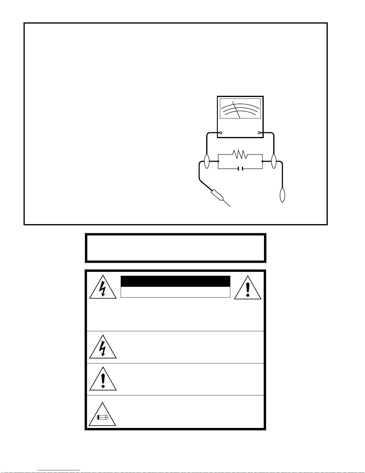
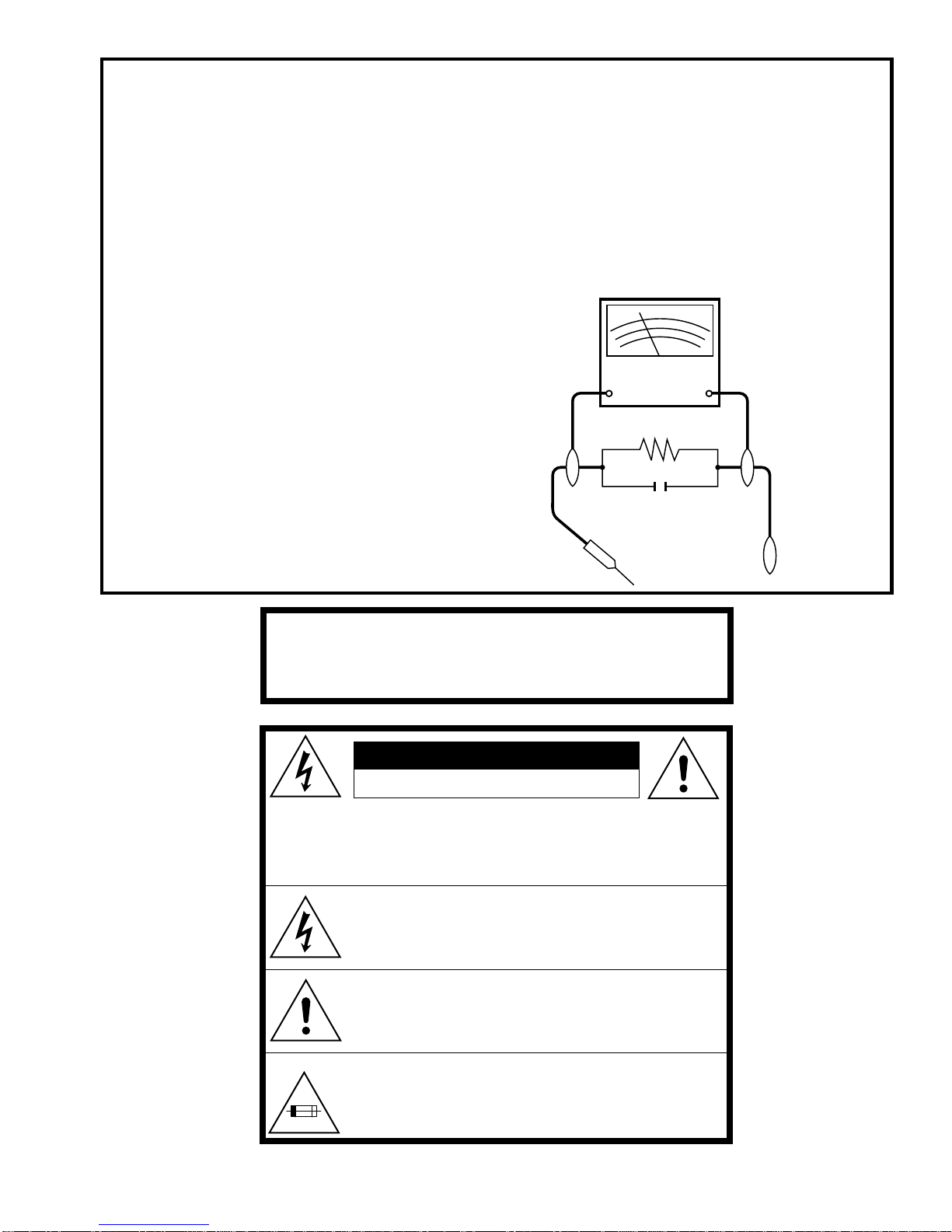
3. Pourêtresûrqu’iln’yaaucunrisquedechocélectrique,
vérifier le courant de fuite de la maniére suivante.
●Brancherle cordon d’alimentationsecteurdirectement
dansune prise decourantde 120 volts.(Nepas utiliser
de transformateur d’isolement pour cet essai).
●Utiliser deux fils à pinces et connecter une résistance
de10watts1,5kohmenparallèleavecuncondensateur
de 0,15 µF en série avec des pièces du coffret
métallique exposées et une masse de terre connue
telle qu’un tuyau ou un conduit d’eau.
●Utiliserun VTVM ouVOMavec une sensibilitéde1000
ohms par volt ou plus ou mesurer la chute de tension
CA entre la résistance (voir diagramme).
●Déposer la connexion de la résistance à toutes les
pièces métalliques exposées ayant un parcours de
retour au châssis (connexions d’antenne, coffret
métallique, tétes de vis, boutons et arbres de
commande, etc.) et mesurer la chute de tension CA
entre la résistance. Inverser la fiche CA (une fiche
intermédiaire non polarisée doit être utilisée à seule fin
de faire ces vérifications.) sur l’appareil et répéter les
mesures de tension CA pour chaque piéce métallique
exposée. Toute lecture de 0,45 Vrms (ceci correspond
à 0,3 mArms CA) ou plus est excessive et signale un
danger de choc qui doit être corrigé avant de rendre le
VCR/DVD magnétoscope à son utilisateur.
3,0A 125V
0,15 µF
SONDE D'ESSAI
VERS PIECES
METALLIQUES
EXPOSEES
VTVM
ECHELLE CA
1,5 KOHMS
10W
CANNECTER A
UNE MASSE DE
TERRE CONNUE

4
DV-NC70U/C
DV-NC72U
2. FEATURES
ËË
ËË
ËCommon Features
•A DVD, CD player and VCR all in one.
•Simultaneous VCR recording and DVD playback.
ËË
ËË
ËVCR
•Hi-Fi Stereo Sound/Double-Azimuth 4-Heads
•Built-in MTS (Multi-channel TV Sound) Decoder
•400 Times Rewind Speed to Fast Forward and Rewind.
•EZ Set Up (Auto Channel/Clock Set Up)
•S-VHS Quasi Playback
•19µClear Picture System (in EP mode)
•Simple Recording Timer
•Sharp Super Picture
•Exact Rec/Tape Remaining
ËË
ËË
ËDVD
•Plays DVD, CD (Digital Audio) discs as well as CD-R/CD-RW discs recorded in MP3 file format
•3D Virtual Surround provides high-quality surround sound
•Digital Gamma correction and Digital Super Picture functions
•Dolby Digital*1/DTS*2digital out capability
•High-quality digital images
•High-quality digital sound
*1Manufactured under license from Dolby Laboratories. "Dolby", "Pro Logic" and the double-D symbol are
trademarks of Dolby Laboratories.
*2"DTS" and "DTS Digital Surround" are trademarks of Digital Theater Systems, Inc.
3. SPECIFICATIONS
Signal System NTSC
INPUT/OUTPUT JACKS
DVD/VCR shared output jacks VIDEO jack: RCA Pin-jack
AUDIO jack: RCA Pin-jack
DVD output jacks VIDEO jack: S-Video jack
Component Y jack: RCA Pin-jack
Component PBjack: RCA Pin-jack
Component PRjack: RCA Pin-jack
AUDIO jack: RCA Pin-jack
DIGITAL AUDIO IF: Coaxial digital
AUDIO output jack: RCA Pin-jack
VIDEO input jacks VIDEO jack: RCA Pin-jack
AUDIO jack: RCA Pin-jack
VCR
Video Recording System Rotary Two-Head Helical Scanning
Number of Video Heads 4
Video Signal Standard NTSC Color System
Audio Recording System 1 Stationary Head for Linear Audio
2 Rotary Heads for Hi-Fi stereo
Tape Width 12.7 mm (1/2 inch)
Tape Speed (SP) 33.35 mm/sec. (1.31 i.p.s.)
(LP) 16.67 mm/sec. (0.66 i.p.s.) (playback only)
(EP) 11.12 mm/sec. (0.44 i.p.s.)
Maximum Recording Time (SP) 160 min. (T-160)
(EP) 480 min. (T-160)

5
DV-NC70U/C
DV-NC72U
3-1. ACCESSORIES
Accessories: Remote control unit ×1, "AA" size battery (R-6, UM/SUM-3) ×2,
VIDEO/AUDIO cable ×1, Round coaxial cable (75 Ohm, 1 m [3-1/4 ft.]) ×1
Channel Coverage VHF 2-13
UHF 14-69
CATV 1-125
Antenna Input 75Ω
Video Input Input level: 0.5 to 2.0 Vp-p (75Ω)
Video Output Output level: 1.0 Vp-p (75Ω)
Audio Output Input level: –8 dBs (47kΩ)
(0 dB = 0.775 Vrms)
Audio Output Output level: –8 dBs (1kΩ)
(0 dB = 0.775 Vrms)
Hi-Fi Audio Dynamic Range: 90 dB
Frequency Response: 20 Hz-20 kHz
Memory Backup 60 seconds
DVD
DVD/VCR shared Video output Output level: 1 Vp-p (75Ω)
Component color output Y output level: 1 Vp-p (75Ω)
PBoutput level: 0.525 Vp-p (75Ω)/75% color
PRoutput level: 0.525 Vp-p (75Ω)/75% color
S video output Y output level: 1 Vp-p (75Ω)
C output level: 0.286 Vp-p (75Ω)
Audio output Output level: 2 Vrms (1 kHz, 0 dB)
Video signal horizontal resolution 500 lines
S/N ratio 60 dB
Audio signal frequency characteristics For DVD linear PCM playback:
4 Hz to 22 kHz (48 kHz sampling)
4 Hz to 44 kHz (96 kHz sampling)
CD playback: 4 Hz to 20 kHz (EIAJ)
S/N ratio CD: 100 dB, 1 kHz (EIAJ)
Dynamic range DVD linear PCM: 96 dB (EIAJ)
CD: 96 dB (EIAJ)
Total harmonic distortion ratio CD: 0.006%
Pickup Wave length: 650 nm
Laser output: Max. 0.7 mW
Operating temperature 5 °C to 35 °C (41 °F to 95 °F)
Storage temperature –20 °C to 55 °C (–4 °F to 131 °F)
Power supply 120 V AC, 60 Hz
Power consumption 28 W
Dimensions 430 mm × 93.5 mm × 356 mm (W × H × D)
(including attachments) (16 15/16" × 3 11/16" × 14 1/32")
Weight 4.8 kg (10.6 lbs)
Specifications are subject to change without notice.
Weight and dimensions are approximate.

6
DV-NC70U/C
DV-NC72U
4. PART NAMES
VCR Main Unit (Front)
OPEN/CLOSE
POWER
EJECT/STOP
REW PLAY
REC
CH
VCR/DVD
SELECTOR
TIMER
VCR DVD
PLAY STOP
AV 2 IN VIDEO L(MONO)-AUDIO-R
/
SEP
VCR
LR
VCR/DVD SELECTOR
POWER
REC
Clock Indicator
Channel Indicator
Tape Counter Indicator
PLAY
Front AUDIO/
VIDEO input
jack
Timer Recording
Indicator
Tape Speeds
Indicator
VCR Mode
Indicator
Operation status
Indicator
Cassette compartment
EJECT/STOP
CH
REW
TIMER indicator
Audio Output
Indicator
VCR Front Panel Display
DVD Main Unit (Front)
DVD Front Panel Display
OPEN/CLOSE
POWER
EJECT/STOP
REW PLAY
REC
CH
VCR/DVD
SELECTOR
TIMER
VCR DVD
PLAY STOP
AV 2 IN VIDEO L(MONO)-AUDIO-R
/
Disc tray
OPEN/CLOSE
POWER
TITLE
indicator
Operation status/Time indicator
TRACK
indicator
CHAPTER
indicator
Disc operation
buttons (PLAY, STOP)
PROGRAM indicator
REPEAT indicator
ANGLE indicator
VIRTUAL surround
indicator
1
2
VCR/DVD SELECTOR
VCR DVD indicator
You can toggle between 1and 2by
pressing the remote control unit’s
DISPLAY button.

7
DV-NC70U/C
DV-NC72U
Main Unit (Rear)
VCR IN FROM
ANTENNA
UHF/VHF
CATV
OUT TO TV
AV 1 IN
AUDIO
R
L
(MONO)
VIDEO
AUDIO
R
L
VIDEO
DVD/VCR
OUT
DVD OUT
DIGITAL
AUDIO
AUDIO
R
L
S-VIDEO
Y
P
R
P
B
COMPONENT
VCR IN FROM
ANTENNA
UHF/VHF
CATV
OUT TO TV
AV 1 IN
AUDIO
R
L
(MONO)
VIDEO
AUDIO
R
L
VIDEO
DVD/VCR
OUT
DVD OUT
DIGITAL
AUDIO
AUDIO
R
L
S-VIDEO
Y
P
R
P
B
COMPONENT
VCR AUDIO input
jacks
ANTENNA IN (antenna
or cable input)
VCR VIDEO input
jack
ANTENNA OUT
DVD/VCR shared
AUDIO output jacks
DVD Coaxial DIGITAL
output jack
DVD S-VIDEO output jack
DVD AUDIO output jacks DVD/VCR shared
VIDEO output jack
COMPONENT VIDEO output jacks
To an AC outlet

8
DV-NC70U/C
DV-NC72U
REV FWD
PLAY
STOP
100
OPEN/
CLOSE
VCR/DVD
SELECTOR VCR MENU
DVD SETUP
TAPE
SPEED
ON
SCREEN
TITLE
DVD MENU
DISPLAY
FUNCTION
CONTROL
PROGRAM ANGLE
CANCEL
RETURN
POWER
TIMER
ON/OFF
TV/VCR EJECT
SET
ENTER
ZERO BACK
SKIP SEARCH
REPLAY
VCR DVDAM/PM INPUT
PAUSE/STILL
REC
SLOW
CH
VCR DVD
SKIP
DPSS
AUDIO
OUTPUT
VCR/DVD COMBINATION
ON SCREEN
TIMER ON/OFF
POWER
DISPLAY
CANCEL
CURSOR ( / / / )
Number buttons
100, AM/PM
PLAY
REW
REC
STOP
TAPE SPEED
VCR/DVD CHANGE Switch
TV/VCR
VCR/DVD SELECTOR
EJECT
VCR MENU
SET
ZERO BACK
SKIP SEARCH
REPLAY
VCR DVD
PAUSE/STILL
59
SLOW
—
/
±
, DPSS
—
/
±
INPUT
SLOW
AUDIO OUTPUT
CH /
FF
Remote Control Unit (VCR Operation Buttons)
The explanations on this page use the VCR/DVD CHANGE Switch in the VCR position.
Do not subject the remote control unit to shock, water or excessive humidity.
The remote control unit may not function if the product’s sensor is in direct sunlight or any other strong light.
Incorrect use of batteries may cause them to leak or burst. Read the battery warnings and use the batteries properly.
Do not mix old and new batteries, or mix brands in use.
Remove the batteries if you do not use the remote control unit for an extended period of time.
Remote Control Unit (DVD Operation Buttons)
The explanations on this page use the VCR/DVD CHANGE Switch in the DVD position.
REV FWD
PLAY
STOP
100
OPEN/
CLOSE
VCR/DVD
SELECTOR VCR MENU
DVD SETUP
TAPE
SPEED
ON
SCREEN
TITLE
DVD MENU
DISPLAY
FUNCTION
CONTROL
PROGRAM ANGLE
CANCEL
RETURN
POWER
TIMER
ON/OFF
TV/VCR EJECT
SET
ENTER
ZERO BACK
SKIP SEARCH
REPLAY
VCR DVDAM/PM INPUT
PAUSE/STILL
REC
SLOW
CH
VCR DVD
SKIP
DPSS
AUDIO
OUTPUT
VCR/DVD COMBINATION
ON SCREEN
POWER
DISPLAY
FUNCTION CONTROL
RETURN
TITLE
CURSOR ( / / / )
Number buttons
REV
STOP
VCR/DVD SELECTOR
REPEAT, PROGRAM
ANGLE
PLAY
DVD MENU
OPEN/CLOSE
DVD SETUP
ENTER
PAUSE/STILL
FWD
SLOW
VCR/DVD CHANGE Switch
SKIP

9
DV-NC70U/C
DV-NC72U
5. MAINTENANCE CHECK ITEMS AND EXECUTIONTIME
Parts Maintained 1,000 hrs. 2,000 hrs.
Pickup
Spindle Unit
Sled Motor
Loading Motor
Belt
Note : Part Replacement
: Cleaning
(For cleaning, use a lint-free cloth danpened with pure isopropyl alcohol.)
Use the following table as a guide to maintain the mechanical parts in good operating condition.
CARES WHEN USING THE PICKUP
1. The laser light having wavelength 650 nm is emitted from the objective lens. BE CAREFUL SO THAT THE LASER
LIGHT DOES NOT ENTER DIRECTLY INTO YOUR EYE.
2. The semiconductor laser may be easily damaged by electrostatic charges. When handling the pickup, take care so that
the electrostatic charge is not generated.
3. The semiconductor laser may be easily damaged by overcurrent. Use the power supply unit which does not give any
spike current when the power is turned on and off.
4. Carefully remove the dust and dirt from the objective lens with the lens blower.
When handling the objective lens, take due care so that it is not contaminated with fingerprint, etc. If the objective lens
is contaminated, impregnate the cleaning paper with a small quantity of solvent (isopropyl alcohol), and gently wipe to
clean.
5. The ozone layer depleting components (ODC) are not used in the production process for the product.
MECHANICAL PARTS REGUIRING PERIODICAL INSPECTION

10
DV-NC70U/C
DV-NC72U
6. DISASSEMBLY METHOD
6-1. DISASSEMBLY METHOD
1)Removing the cabinet.
(1) Remove the four screws 1and one screw 2.
2)Removing the front panel.
(1) Remove the two screws 3.
(2) Release the six hooks 4.
3)Removing the front PWB.
(1) Release the one hook 5and tilt the PWB
toward you to remove it.
(2) Release the one hook 6and tilt the PWB
toward you to remove it.
4)Removing the DVD mechanism.
(1) Remove the four screws 7 to remove the DVD REINF.
angle.
(2) Remove the two screws 8and two screws 9.
(3) Remove the two screws 0 to remove the Angle (DVD) .
2
1
1
4
35
6
4
4
4
9
10
9
10
8
7
12
11
(4) Remove the DVD Shield (lower) q.
(5) Remove the four screws wto remove the DVD Main PWB
Unit from Angle (DVD).

11
DV-NC70U/C
DV-NC72U
13
16
14
15
19
18
17
20
(6) Remove the two screws e to remove the Power PWB
Unit.
5)Removing the Cassette Housing Control/VCR Mechanism.
(1) Remove the two screws r.
(2) Remove the one screw t.
(3) Remove the two screws y.
6)Removing the Antenna Terminal Cover/VCR Main PWB Unit.
(1) Remove the six screws u.
(2) Remove the two screws i.
(3) Remove the one screw o.
7)Removing the Bottom Plate.
(1) Remove the one screw p.

12
DV-NC70U/C
DV-NC72U
Parts Code Price Code Name/Description
QCNW-8571GEZZ AN Extension cable (wire), 9pin 500mm
DVD Main CN3201–Power CN201
6-2. EXTENSION CABLE USE POINT (ONE PLACE)
Extension Cable Diagram
Power PWB
CN201
Tuner
CN3201
DVD Main PWB
DVD Mechanism
F-AV PWB VCR/DVD Display PWB
VCR Mechanism
VCR Main PWB
QCNW-8571GEZZ
9 pin

13
DV-NC70U/C
DV-NC72U
<Replacing the Pickup and the Spindle Motor>
Since the Pickup optical axis and turntable inclination of DVD are adjusted with higher accuracy, make a replacement as a
mechanism service chassis ass'y.
Front Side
Sled Motor Lead Wire
Pickup FFC
Traverse Fixing Screw
Loading Motor Lead Wire
Pickup Interface PWB
Pickup FFC
Short Land
6-3. REPLACEMENT OF MAIN PARTS
<Take out disk>
1. Remove the mechanism with angle from the set. (refer to 33 on page 104. Remove K , M , N )
2. It is in such cases as the thin driver, and it is pushed in slowly, and a tray is drawn in the arrow direction the Slide Rack on the
left of the base chassis.
3. Take out disk.
<Disassembling and assembling the mechanism chassis>
1. After setting the mechanism chassis to the angle state, ground it to prevent the electrostatic discharge damage of the pickup.
2. Remove the DVD Shield (lower) 40 (refer to the illustration on page 104).
3. Remove P , Q from the DVD Main PWB Unit 27 . (Pickup Relay FFC 58 isn't removed.) (refer to the illustration on page 104)
4. Remove screws fixing the base chassis (located at the back right and at front left when facing the set).
5. With the Pickup FFC connected, turn over the base chassis and short (solder) two short lands on the pickup interface PWB in
order to prevent the electrostatic discharge damage of the pickup.
6. Remove the Pickup FFC from the Main PWB.
7. Remove the Pickup FFC from the Pickup Interface PWB.
8. Remove the Traverse Fixing Screws to remove the Traverse Chassis ass'y.
Note: After assembling and wiring, remove the solder joint of the short land. If short-circuited, a disk is not played back.

14
DV-NC70U/C
DV-NC72U
7. OPERATION OF PICKUP
7-1. CIRCUIT CONFIGURATION OF PICKUP
The pickup unit reads signals from the disk, and the flexible cable is connected to the board. The following signals flow through the
cable.
7-2. EQUIVALENT CIRCUIT OF PICKUP 7-3. POLARITIES OF SIGNAL
Focus When electric current is flowed
FO+, FO- from FO+ to FO-, the lens comes
to near the disk.
Tracking When electric current is flowed
TR+, TR- from TR+ to TR-, the lens goes
toward the outer circumference.
FO+
TR–
TR+
FO–
ACTUATOR
OSC V
OS
–
+
–
+
–
+
–
+
HOLOGRAM LASER UNIT
1
2
3
4
5
6
7
8
9
10
11
12
13
14
15
16
17
18
19
20
1
TR–
FO+
TR+
FO–
VR
PD
V
CC
GND
LD
GND
V
OS
NC
NC
V
ref
(VCC/2)
VA
VD
NC
GND
VB
VC
(NC)
Power adjust
HIGH-FREQUENCY CONVOLUTION
LD
PD
VA
VB
VC
VD
V
ref
V
cc
GND
7-4. SIGNALS OF PICKUP
7-4-1. Tracking drive signal (TR+, TR-)
The signal drives the tracking servo mechanism which projects the beam on the track by moving the objective lens (OL) to the outer
or inner circumference (at a right angle against the track) of the disk.
7-4-2. Focus drive signal (FO+, FO-)
The signal drives the focus servo mechanism which aligns the focus on the pit of the disk
by elevating OL (vertically against the disk surface.)
The VR terminal is connected to GND.
2-focus objective lens
Actuator assembly
7-4-3. Monitor Diode (PD)
Since the laser diode largely varies output of the laser light even if the flowing current is slightly varied, the projection
light is detected with the monitor diode to control the laser light to be equally output.
Since the current varies on the monitor diode according to the intensity of the received light of the laser diode, the drive current of
the laser diode is reduced if the current of the monitor diode increases. On the contrary, the drive current of the laser diode is increased
if the current of the monitor diode decreases.
As the projection light of the laser diode becomes stronger, the current of the monitor diode increases to increase the current which
flows into the monitor diode output (PD). This is input to the pin 44 of IC301 and is compared with the reference voltage to control
the drive current of the laser diode.
The circuit is called ALPC (Automatic Laser Power Control).
7-4-4. Laser diode drive current control (LD)
Power supply to drive the laser diode
7-4-5. High-frequency convolution module power supply (VOSC)
The high-frequency convolution imposes the high-frequency signal on the DC current to impose the high frequency on the drive
current of the laser. Thus, the interference of outgoing light and reflected light is prevented.
LD PD
7-4-6. HF Signal (VA, VB, VC, VD)
Signals recorded in the disk
When the quantity of laser light increases, the
current shown in figure increases and the PD
terminal voltage rises.
IC301 is used to control. The LD terminal voltage
lowers, and the quantity of light reduces. (IC301 is
actuated by voltage input.)

15
DV-NC70U/C
DV-NC72U
VROATSV CD
11.
JiGHMEC-M005 CK
10. JiGDRiVER-6 BM
9.
JiGDRiVERH-4
AP
4. Torque Driver JiGTD1200 CB
8. ADJUSTMENT, REPLACEMENT AND ASSEMBLY OF MECHANICAL UNITS
The explanation given below relates to the on-site general service (field service) but it does not relates to the adjustment
and replacement which need high-grade equipment, jigs and skill. For example, the drum assembling, replacement and
adjustment service must be performed by the person who have finished the technical courses.
8-1 MECHANISM CONFIRMATION ADJUSTMENT JIG
So as to perform completely the mechanism adjustment prepare the following special jigs. So as to maintain the initial
performance of the machine the maintenance and check are necessary. Utmost care must be taken so that the tape is
not damaged. If adjustment needs any jig, be sure to use the required jig.
JiGTG1200 CN
JiGMP0001 BY
1. Torque Cassette Meter JiGVHT-063 CZ
No. Jig ltem Part No. Code Configuration Remarks
JiGTG0090 CM
3. Torque Gauge Head JiGTH0006 AW
JiGRH0002 BR
JiGSG2000 BS
JiGSG0300 BF
7. JiGADP003 BK
Tension Gauge
These Jigs are used for checking
and adjusting the reel disk height.
When fixing any part to the threaded
hole using resin with screw, use the
jig. (Specified torque 5 kg)
This cassette torque meter is used for check-
ing and adjusting the torque of take-up for
measuring tape back tension.
These Jigs are used for checking
and adjusting the torque of take-up
and supply reel disks.
Master Plane Jig and
Reel Disk Height
Adjusting Jig
Pinch pressing force
measuring jig
This Jig is used with the tension
gauge.Rotarytransformerclearance
adjusting jig.
There are two gauges used for the
tension measurements, 300 g and
2.0 kg.
These tapes are especially used for
electrical fine adjustment.
Video Audio HiFi Audio Track
525 Monoscope 7k — 58µm
NTSC Color Bar 1k — 58µm
VROEFZCS BG
OR
VROEFZHS BH
1k
This screwdriver is used for adjusting the
guide roller height.
For X value adjustment
This Jig is used for adjustment
of tension pole.
X value adjustment
gear driver
Tension Pole
Adjustment Driver
2.3k
Black Level
(only SYNC) signal
—19µm
2. Torque Gauge
6.
5.
8. Alignment Tape
Guide roller height
adjustment driver

16
DV-NC70U/C
DV-NC72U
8-2 MAINTENANCE CHECK ITEMS AND EXECUTION TIME
Perform the maintenance with the regular intervals as follows so as to maintain the quality of machine.
NOTE : Part replacement. : Cleaning : Apply grease
<Specified> Cleaning liquid Industrial ethyl alcohol
* This mechanism does not need electric adjustment with variable resistor. Check parts. If any deviation is found,
clean or replace parts.
Maintained
Parts Remarks
500
hrs. 1000
hrs. 1500
hrs. 2000
hrs. Possible symptom
encountered
Guide roller ass’y
Sup guide shaft
Reverse guide
Slant pole on pole base
Full erase head
A/C head
Upper and lower drum ass’y
Capstan D.D. motor
Pinch roller
Reel belt
Tension band ass’y
Loading motor
Idler ass’y
Limiter pulley
Supply/take-up main brake levers
Color and beating
Small sound or sound
distortion
Poor S/N ratio, no color
Poor flatness of the
envelope with alignment
tape
No tape running,
uneven color
No tape running, tape
slack
No tape running, tape
slack, no fast forward/
rewind motion
Lateral noises Head
occasionally blocked
Abnormal rotation or significant
vibration requires replacement.
Clean tape contact part with the
specified cleaning liquid.
Clean tape contact area with the
specified cleaning liquid.
Clean rubber and rubber contact
area with the specified cleaning
liquid.
Screen swaying
Cassette not loaded or
unloaded
No tape running, tape
slack
Tape slack
Video head cleaning procedure
1. Apply one drop of cleaning liquid to the cleaning paper with the baby oiler.
2. Gently press the cleaning paper against the video head to fix your finger, and move the upper drum so that each head
is passed to and fro 5 times (do not move the cleaning paper).
3. Wipe with the dry cleaning paper.
Notes :
•Use the commercially available ethanol of Class 1 as
cleaning liquid.
•Since the video head may be damaged, do not move up
and down the cleaning paper.
•Whenever the video head is cleaned, replace the clean-
ing paper.
•Do not apply this procedure for the parts other than the
video head.
Parts Code Description Code
ZPAPRA56-001E Cleaning Paper AW
ZOiLR-02-24TE Babe Oiler (Spoit) AH
Gently press the cleaning paper to
fix with your finger, and rotate the
upper drum to clean.
Move to and fro 5 times for each head.
(Do not move the cleaning paper.)
Rotate the upper drum
with one hand.

17
DV-NC70U/C
DV-NC72U
8-3. FUNCTION OF MAJOR MECHANICAL PARTS (TOP VIEW)
No. Function No. Function
1 Full erase head
2 Supply pole base ass’y
3 Tension arm
4 Idler wheel ass’y
5 Open guide
6 Supply reel disk
7 Supply main brake
8 Take-up main brake
9 Pinch drive cam
10 A/C head ass’y
11 Reverse guide lever ass’y
12 Reel relay gear
13 Take-up reel disk
14 Pinch roller lever ass’y
15 Drum ass'y
16 Loading motor block
17 Drum driver motor
18 Take-up pole base ass'y
26 Auto head cleaner Ass'y
17 15 26
11
5
9
14
12
8
16
13
4
6
2
7
3
1
18 10

18
DV-NC70U/C
DV-NC72U
FUNCTION OF MAJOR MECHANICAL PARTS (BOTTOMVIEW)
No. Function No. Function
19 Syncro Gear
20 Master cam
21 Capstan D.D. motor
22 Reel belt
23 Clutch lever
24 Limiter pulley ass’y
25 Shifter
25
24
21
22
19
20
23

19
DV-NC70U/C
DV-NC72U
8-4-2 CARES WHEN REASSEMBLING
INSTALLING THE CASSETTE HOUSING
When the cassette housing is installed on the mechanism,
the initial setting is essential condition.
There are two initial setting methods, namely electrical and
mechanical.
1. Electrical initial setting
So as to perform initial setting of mechanism execute the
Step 1 of Installation of cassette housing. After ascertaining
the return to the initial setting position install the cassette
housing. (Conditions: When mechanism and PWB have
been installed)
8-4-1 DISASSEMBLING THE MECHANISM
1. When removing the mechanism from the set.
Removethe twoscrews1whichconnecting mechanism
and main frame.
Take out vertically the mechanism so that it does not
damage the adjacent parts.
2. Removing the mechanism and cassette housing.
Remove the two screws 2fixing the cassette housing
to the mechanism, and remove the cassette housing.
PinchDrive Cam
Synchro Gear Master cam
Main Chassis Drive Lever
8-4. DISASSEMBLY AND REASSEMBLY
Cassette Control
Housing
Mechanism
Chassis
Main PWB
21

20
DV-NC70U/C
DV-NC72U
INSTALLING THE MECHANISM ON PWB
Lower vertically the mechanism, paying attention to the
mechanism edge mode SW position, (Set the mode SW
position to 270°and make sure the master cam position
hole also in 270°position) and install the mechanism with
due care so that the parts are not damaged.
* Please make sure to insert correctly.
If not, strange moving will occur and will couse mecha-
nism damage.
PARTS WHICH NEED PARTICULAR CARE
When installing the mechanism chassis on the PWB unit,
take care so as to prevent deformation due to contact of
mechanism chassis with REC Tip SW.
2. Mechanical initial setting
•Rotate the worm gear by pushing the flange manually
until return to initial position.
•When apply power supply to rotate the loading motor,
please remove/unsolder at least one terminal wire.
•If voltage applied to loading motor without disconnecting
the terminal wire, there is a possibility the capstan motor
IC will damage. Rotate the flange of worm gear by using thin stick.
CW ---- Loading direction
CCW --Ejection direction
Note
Be careful not to damage the gear of worm gear
and worm wheel gear. It might cause a strange sound.
•The maximum applied voltage is 9V. If more than 9V,
there is a possibility the mechanism will damage.
•After ascertaining the return to the initial set position
install the cassette housing in the specified position. (This
method is applied only for the mechanism.)
90°
180°
270°
0°
Connectorfor
CapstanMotor
Connectorfo
r
ACHead
ConnectorforR/T
AEConnector
EndSensor
RECTipSW
This positioning hole
should be at frontside.
Master Cam Position
MODE SW
Start Sensor
This pin should be
at frontside.
This manual suits for next models
2
Table of contents
Other Sharp DVD VCR Combo manuals

Sharp
Sharp DV-NC70W User manual

Sharp
Sharp DV-RW360Y User manual

Sharp
Sharp DV-NC55S User manual

Sharp
Sharp DV-NC70 User manual

Sharp
Sharp DV-NC80W User manual

Sharp
Sharp DV-RW260H User manual

Sharp
Sharp DV-NC85 User manual

Sharp
Sharp DV-NC200S User manual

Sharp
Sharp DV-NC70H User manual

Sharp
Sharp DV-NC65H User manual

Sharp
Sharp DV-RW250X User manual

Sharp
Sharp DV-NC65S User manual

Sharp
Sharp DV-NC150U User manual

Sharp
Sharp DV-NC55U User manual

Sharp
Sharp DV-NC230(RU) User manual

Sharp
Sharp DV-RW370X User manual

Sharp
Sharp DV-RW250S User manual

Sharp
Sharp DV-RW550U User manual

Sharp
Sharp DV-RW550U User manual

Sharp
Sharp DV-NC230S User manual