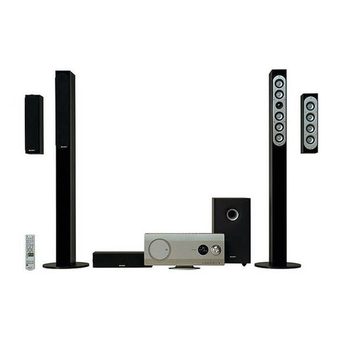
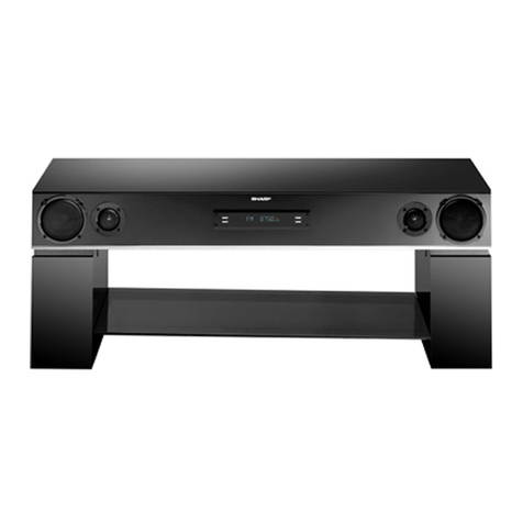
Sharp HT-CN150DVW User manual

HT-CN150DVW
1
Home Theater with DVD
Page
SPECIFICATIONS..................................................................................................................................................................2
LASER BEAM SAFETY PRECAUTIONS ..............................................................................................................................4
IMPORTANT SAFEGUARDS AND PRECAUTIONS.............................................................................................................5
STANDARD NOTES FOR SERVICING.................................................................................................................................6
OPERATING CONTROLS AND FUNCTIONS......................................................................................................................10
TROUBLESHOOTING..........................................................................................................................................................13
BLOCK DIAGRAMS..............................................................................................................................................................16
SCHEMATIC DIAGRAMS / IC’S PIN VOLTAGE...................................................................................................................18
WAVEFORMS.......................................................................................................................................................................40
WIRING DIAGRAM...............................................................................................................................................................42
SYSTEM CONTROL TIMING CHARTS................................................................................................................................53
IC PIN FUNCTION DESCRIPTIONS....................................................................................................................................54
LEAD IDENTIFICATIONS....................................................................................................................................................100
FL DISPLAY.........................................................................................................................................................................101
PART GUIDE
SERVICE MANUAL
No. S7501HTN150DW
SHARP CORPORATION
CONTENTS
This document has been published to be used for
after sales service only.
The contents are subject to change without notice.
HT-CN150DVW
MODEL
• In the interests of user-safety (Required by safety regula-
tions in some countries) the set should be restored to its
original condition and only parts identical to those specified
be used.
PLAY STOPFUNCTION +
VOLUME
SKIP
MODE
OPEN/CLOSE
MIN.
ON/STAND-BY
MIC
-
HOMETHEATER WITH DVD HT-CN150DVW
MP3
MAX.
MICVOLUME
REMOTE
SENSOR
ENTER
LANGUAGE
SLOW/
MEMORY
ADJ/VOL
MENU/PBCTITLE
ON/STANDBY
FUNCTION I/PSCAN
OPEN/CLOSE
SLEEP MIC KEY ECHO
DISPLAY DIRECT ZOOM PROG
LISTENING REPEAT A-B
RETURN
SETUP
STOP PLAY/PAUSE
TUNING
V
V
PRESET
V
V
NTSC/PAL ST/MO MODE
STEP ANGLE SUBTITLE AUDIO
EQ
MUTE
92LWIR150Z04D7
AUDIO/VIDEO
SUPERWOOFER 5.1 SPEAKER SYSTEM

HT-CN150DVW
2
AudioCD-DV999W/CD-DV777WService ManualCD-DV999W/CD-DV777WMarketE
SPECIFICATIONS
●General
●Amplifier (HT-CN150DVW)
●DVD player
●Tuner
As part of our policy of continuous improvement, SHARP reserves the right to make design and specification changes
for product improvement without priornotice. The performance specification figures indicated are nominal values of pro-
duction units. There may be some deviations from these values in individual units.
Power source AC 110 - 127 V / 220 - 240 V, 50/60 Hz
Power consumption HT-CN150DVW: Power on: 80 W
Dimensions Width: 430 mm (17-1/8")
Height: 60 mm (2-3/8")
Depth: 345 mm (13-3/4")
Weight 4.3 kg (9.5 lbs.)
Audio input terminals Analogue input (IN 1): RCA type × 1 pair (L/R)
Analogue input (IN 2): RCA type × 1 pair (L/R)
Audio output terminals Analogue output (OUT): RCA type × 1 pair (L/R)
Video output terminals S-video output: S-terminal × 1 Video output: RCA type × 1
Output power Front speakers: RMS: 60 W (30 W + 30 W) (10 % T.H.D., 1 kHz)
Centre speaker: RMS: 30 W (10 % T.H.D., 1 kHz)
Surround speakers: RMS: 60 W (30 W + 30 W) (10 % T.H.D., 1 kHz)
Subwoofer: RMS: 50 W (10 % T.H.D., 100 Hz)
Signal system PAL/NTSC colour
Supported disc types DVD (with the same region number on the back of the unit or ALL), SVCD, VCD, audio CD,
CD-R, CD-RW, MP3
Video signal Horizontal resolution: 525 linesS/N ratio: 56 dB
Audio signal Frequency characteristics Linear PCM DVD: 20 Hz to 20 kHz
(sampling rate: 48 kHz)
20 Hz to 20 kHz
(sampling rate: 96 kHz)
CD: 20 Hz to 20 kHz
S/N ratio CD: 65 dB (1 kHz)
Dynamic range Linear PCM DVD: 95 dB CD: 94 dB
Total harmonic distortion ratio 0.2 % maximum
Frequency range FM: 88 - 108 MHz
AM: 531 - 1602 kHz

HT-CN150DVW
3
●Front speakers
●Surround speakers
●Center speaker
●Subwoofer
Type Full range speaker system (magnetic shield)
8 cm (3-1/8") speaker
Maximum input power 40 W
Impedance 8 ohms
Dimensions Width: 91.5 mm (3-5/8")
Height: 139.5 mm (5-1/2")
Depth: 100 mm (3-15/16")
Weight 0.7 kg (1.5 lbs.)/each
Type Full range speaker system
8 cm (3-1/8") speaker
Maximum input power 40 W
Impedance 8 ohms
Dimensions Width: 91.5 mm (3-5/8")
Height: 139.5 mm (5-1/2")
Depth: 100 mm (3-15/16")
Weight 0.5 kg (1.1 lbs.)/each
Type Full range speaker system
8 cm (3-1/8") speaker
Maximum input power 40 W
Impedance 8 ohms
Dimensions Width: 91.5 mm (3-5/8")
Height:169.5 mm (6-11/16")
Depth: 100 mm (3-15/16")
Weight 0.7 kg (1.5 lbs.)
Type Subwoofer system
13 cm (5-1/8") Subwoofer
Maximum input power 70 W
Impedance 4 ohms
Dimensions Width:200 mm (7-7/8")
Height: 338 mm (13-9/16")
Depth: 303 mm (12-3/16")
Weight 4.2 kg (9.2 lbs.)

HT-CN150DVW
4
LASER BEAM SAFETY PRECAUTIONS
This DVD player uses a pickup that emits a laser beam.
The laser beam is emitted from the location shown in the figure. When checking the laser diode, be sure to keep your eyes at least
30cm away from the pickup lens when the diode is turned on. Do not look directly at the laser beam.
Caution: Use of controls and adjustments, or doing procedures other than those specified herein, may result in hazardous radiation
exposure.
Do not look directly at the laser beam coming
from the pickup or allow it to strike against
your skin.
Drive Mecha Assembly
Laser Beam Radiation
Laser Pickup
Turntable

HT-CN150DVW
5
IMPORTANT SAFEGUARDS AND PRECAUTIONS
1. IMPORTANT SERVICE NOTES
1. NOTES DE SERVICE IMPORTANTES
SSVM
AC SCALE
1.5k ohms.
10W
0.15
TEST PROBE
TO EXPOSED
METAL PARTS
CONNECT TO
KNOWN EARTH
GROUND
CONNECT TO
KNOWN EARTH
GROUND
F
VTVM
AC SCALE
1.5k ohms
10W
TO EXPOSED
METAL PARTS
TEST PROBE
0.15 F
BEFORE RETURNING THE DVD VIDEO PLAYER
Before returning the DVD video player to the user,
perform the following safety checks.
1. Inspect all lead dress to make certain that leads are
not pinched or that hardware is not lodged between
the chassis and other metal parts in the DVD video
player.
2. Inspect all protective devices such as non-metallic
control knobs, insulation materials, cabinet backs,
adjustment and compartment covers or shields,
isola-tion resistor/capacitor networks, mechanical
insula-tors etc.
3. To be sure that no shock hazard exists, check for
current in the following manner.
●Plug the AC line cord directly into a 230 volt AC outlet
(Do not use an isolation transformer for this test).
●Using two clip leads, connect a 1.5k ohm, 10 watt
resistor paralleled by a 0.15µF capacitor in series with
all exposed metal cabinet parts and a known earth
ground, such as a water pipe or conduit.
●Use an DVM or VOM with 1000 ohm per volt, or higher,
sensitivity or measure the AC voltage drop across the
resistor (See Diagram).
●Move the resistor connection to earth exposed metal
part having a return path to the chassis (metal cabinet,
screw heads, knobs and control shafts, etc.) and
measure the AC voltage drop across the resistor.
Reverse the AC plug on the set and repeat AC voltage
measurements for each exposed part. Any reading of
1.4V rms (this corresponds to 0.7mA rms AC.) or more
is excessive and indicates a potential shock hazard
which must be corrected before returning the DVD
video player to the owner.
AVANT DE RENDRE LE REPRODUCTOR DE VÍDEO
DVD
Avant de rendre le reproductor de vídeo DVD à l'utilisateur,
effectuer les vérifications de sécurité suivantes.
1. Vérifier toutes les gaines de fil pour être sûr que les fils
ne sont pas pincés ou que le matériel n'est pas coincé
entre le châssis et les autres pièces métalliques dans le
reproductor de vídeo DVD.
2. Vérifier tous les dispositifs de protection tels que les
boutons de commande non métalliques, les matériaux
d'isolement, le dos du coffret, les couvercles de
compartiment et ajustement ou les boucliers, les
réseaux de résistance / condensateur d'isolement, Ies
isolateurs mécaniques, etc.
3. Pour être sûr qu'il n'y a aucun risque de choc électrique,
vérifier le courant de fuite de la maniére suivante.
●Brancher le cordon d'alimentation secteur directement
dans une prise de courant de 230 volts. (Ne pas utiliser
de transformateur d'isolement pour cet essai).
●Utiliser deux fils à pinces et connecter une résistance de
10 watts 1,5 kohm en parallèle avec un condensateur
de 0,15 F en série avec des pièces du coffret métallique
exposées et une masse de terre connue telle qu'un
tuyau ou un conduit d'eau.
●Utiliser un DVM ou VOM avec une sensibilité de 1000
ohms par volt ou plus ou mesurer la chute de tension
CA entre la résistance (voir diagramme).
●Déposer la connexion de la résistance à toutes les de
pièces métalliques exposées ayant un parcours de
retour au châssis (coffret métallique, tétes de vis,
boutons et arbres de commande, etc.) et mesurer la
chute de tension CA entre la résistance. Inverser la
fiche CA (une fiche intermédiaire non polarisée doit être
utilisée à seule fin de faire ces vérifications.) sur
l’appareil et répéter les mesures de tension CA pour
chaque piéce métallique exposée. Toute lecture de 1,4
V rms (ceci correspond à 0,7 mA rms CA) ou plus est
excessive et signale un danger de choc qui doit être
corrigé avant de rendre le reproductor de vídeo DVD à
son utilisateur.
HT-CN150DVW
6
STANDARD NOTES FOR SERVICING
Circuit Board Indications
a. The output pin of the 3 pin Regulator ICs is indicated
as shown.
Top View
Out In
Bottom View
Input
b. For other ICs, pin 1 and every fifth pin are indicated
as shown.
5
10
Pin 1
< Bottom View >
c. The 1st pin of every male connector is indicated as
shown.
Pin 1
< Bottom View >
Instructions for Connectors
1. When you connect or disconnect the FFC (Flexible
Foil Connector) cable, be sure to first disconnect the
AC cord.
2. FFC (Flexible Foil Connector) cable should be in-
serted parallel into the connector, not at an angle.
FFC Cable
Connector
CBA
* Be careful to avoid a short circuit.
Using lead-free wire solder
When fixing the PWB soldered with the lead-free solder,
apply lead-free wire solder. Repairing with conventional
lead wire solder may cause damage or accident due to
cracks.
As the melting point of lead-free solder (Sn-Ag-Cu) is
higher than the lead wire solder by 40°C, we recommend
you to use a dedicated soldering bit, if you are not
familiar with how to obtain lead-free wire solder or
soldening bit, contact our service station or service
ranch in your area.
Soldering
As the melting point of lead-free solder (Sn-Ag-Cu) is
about 220°C which is higher than the conventional lead
solder by 40°C, and as it has poor solder wettabillty, you
may be apt to keep the soldering bit in contact with the
PWB for extended period of time. However, Since the
land may be peeled off or the maximum heat-resistance
temperature of parts may be excoeded, remove the bit
from the PWB as soon as you conurm the steady
soldering condition.
Lead-free solder contains more tin, and the end of the
soldering bit may be easily corroded. Make sure to tum
on and off the power of the bit as required. if a different
type of solder stays on the tip of the soldering bit, it is
alloyed with lead-free solder. Clean the bit after every
use of it.
When the tip of the soldering bit is blackened during
use, file it with steel wool or fine sandpaper.
Becareful when replacing parts with polarity indication
on the PWB silk.
Lead-free wire solder for servicing
Part No. Description Code
ZHNDAi123250E J 0.3mm 250g(1roll) BL
ZHNDAi126500E J 0.6mm 500g(1roll) BK
ZHNDAi12801KE J 1.0mm 1kg(1roll) BM

HT-CN150DVW
7
How to Remove / Install Flat Pack-IC
1. Removal
With Hot-Air Flat Pack-IC Desoldering Machine:
(1) Prepare the hot-air flat pack-IC desoldering ma-
chine, then apply hot air to the Flat Pack-IC (about 5
to 6 seconds). (Fig. S-1-1)
Fig. S-1-1
(2) Remove the flat pack-IC with tweezers while apply-
ing the hot air.
(3) Bottom of the flat pack-IC is fixed with glue to the
CBA; when removing entire flat pack-IC, first apply
soldering iron to center of the flat pack-IC and heat
up. Then remove (glue will be melted). (Fig. S-1-6)
(4) Release the flat pack-IC from the CBA using twee-
zers. (Fig. S-1-6)
Caution:
1. Do not supply hot air to the chip parts around the flat
pack-IC for over 6 seconds because damage to the
chip parts may occur. Put masking tape around the
flat pack-IC to protect other parts from damage.
(Fig. S-1-2)
2. The flat pack-IC on the CBA is affixed with glue, so
be careful not to break or damage the foil of each pin
or the solder lands under the IC when removing it.
Hot-air
Flat Pack-IC
Desoldering
Machine
CBA
Flat Pack-IC
Tweezers
Masking
Tape
Fig. S-1-2
With Soldering Iron:
(1) Using desoldering braid, remove the solder from all
pins of the flat pack-IC. When you use solder flux
which is applied to all pins of the flat pack-IC, you can
remove it easily. (Fig. S-1-3)
Flat Pack-IC Desoldering Braid
Soldering Iron
Fig. S-1-3
(2) Lift each lead of the flat pack-IC upward one by one,
using a sharp pin or wire to which solder will not
adhere (iron wire). When heating the pins, use a fine
tip soldering iron or a hot air desoldering machine.
(Fig. S-1-4)
Fine Tip
Soldering Iron
Sharp
Pin
Fig. S-1-4
(3) Bottom of the flat pack-IC is fixed with glue to the
CBA; when removing entire flat pack-IC, first apply
soldering iron to center of the flat pack-IC and heat
up. Then remove (glue will be melted). (Fig. S-1-6)
(4) Release the flat pack-IC from the CBA using twee-
zers. (Fig. S-1-6)
With Iron Wire:
(1) Using desoldering braid, remove the solder from all
pins of the flat pack-IC. When you use solder flux
which is applied to all pins of the flat pack-IC, you can
remove it easily. (Fig. S-1-3)
(2) Affix the wire to a workbench or solid mounting point,
as shown in Fig. S-1-5.
(3) While heating the pins using a fine tip soldering iron
or hot air blower, pull up the wire as the solder melts
so as to lift the IC leads from the CBA contact pads
as shown in Fig. S-1-5.

HT-CN150DVW
8
(4) Bottom of the flat pack-IC is fixed with glue to the
CBA; when removing entire flat pack-IC, first apply
soldering iron to center of the flat pack-IC and heat
up. Then remove (glue will be melted). (Fig. S-1-6)
(5) Release the flat pack-IC from the CBA using twee-
zers. (Fig. S-1-6)
Note:
When using a soldering iron, care must be taken to
ensure that the flat pack-IC is not being held by glue.
When the flat pack-IC is removed from the CBA,
handle it gently because it may be damaged if force
is applied.
To Solid
Mounting Point
Soldering Iron
Iron Wire
or
Hot Air Blower
Fig. S-1-5
Fine Tip
Soldeing Iron
CBA
Flat Pack-IC
Tweezers
Fig. S-1-6
2. Installation
(1) Using desoldering braid, remove the solder from the
foil of each pin of the flat pack-IC on the CBA so you
can install a replacement flat pack-IC more easily.
(2) The "●" mark on the flat pack-IC indicates pin 1. (See
Fig. S-1-7.) Be sure this mark matches the 1 on the
PCB when positioning for installation. Then presol-
der the four corners of the flat pack-IC. (See Fig. S-
1-8.)
(3) Solder all pins of the flat pack-IC. Be sure that none
of the pins have solder bridges.
Example :
Pin 1 of the Flat Pack-IC
is indicated by a " " mark. Fig. S-1-7
Presolder
CBA
Flat Pack-IC
Fig. S-1-8

HT-CN150DVW
9
Instructions for Handling
Semi-conductors
Electrostatic breakdown of the semi-conductors may
occur due to a potential difference caused by electrostatic
charge during unpacking or repair work.
1. Ground for Human Body
Be sure to wear a grounding band (1MΩ) that is properly
grounded to remove any static electricity that may be
charged on the body.
2. Ground for Workbench
Be sure to place a conductive sheet or copper plate with
proper grounding (1MΩ) on the workbench or other
surface, where the semi-conductors are to be placed.
Because the static electricity charge on clothing will not
escape through the body grounding band, be careful to
avoid contacting semi-conductors with your clothing.
CBA
< Incorrect >
CBA
Grounding Band
Conductive Sheet or
Copper Plate
< Correct >

HT-CN150DVW
10
OPERATING CONTROLS AND FUNCTIONS
■Main unit (front panel)
1. On/Stand-by Button
2. Disc Tray
3. Disc Tray Open/Close Button
4. Remote Sensor
5. Power Stand-by Indicator
6. Function Button
7. Speaker Level Mode Button
8. Play or Pause Button
9. Stop Button
10. Chapter (track) Skip Down or Preset/Tuning Down Button
11. Chapter (track) Skip Up or Preset/Tuning Up Button
12. Volume Up and Down or Speaker Level Adjust Buttons
13. Microphone Volume Control
14. Microphone Socket
15. Speaker Indicators
(1) Left Front Speaker Indicator
(2) Centre Speaker Indicator
(3) Right Front Speaker Indicator
(4) Left Surround Speaker Indicator
(5) Subwoofer Indicator
(6) Right Surround Speaker Indicator
16. Dolby Pro Logic Indicator
17. Dolby Digital Signal Indicator
18. P - SCAN mode
19. DVD Indicator
20. Pause Indicator
21. Play Indicator
22. Title Indicator
23. Track Indicator
24. Tuner Preset Indicator
25. Chapter Indicator
26. Programme Indicator
27. Sleep Indicator
28. Repeat Indicator
29. A - B Repeat Indicator
30. DTS Signal Indicator
31. Stereo (2-ch) or FM Stereo Receiving Indicator
32. SVCD/VCD/CD Indicator
33. MP3 or JPEG Indicator
PLAY STOPFUNCTION +
VOLUMESKIPMODE
OPEN /CLOSE
MIN.
ON / STAND-BY
MIC
-
HOME THEATER WITH DVD HT-CN150DVW
MAX.
MIC VOLUME
REMOTE
SENSOR
1
5 6 8 9
13710 1411
2 3 4
12
KHz
A-B
REPEAT 1SLEEPPROGCHPPRESETTRKTITLEP-SCAN
CD MP3STEREO V
MHz
DIGITAL
Pro Logic
RL
RSLS
C
S
(1)
15
RL
RSLS
C
S
(3)(2)
(4) (6)(5)
16 17 18
2928272625
242319 20 21 22
30 31 32 33
MP3

HT-CN150DVW
11
■Main unit (rear panel)
1. AC Power Input Socket
2. Cooling Fan
3. Speaker Terminals
4. Audio Input Sockets (TV/AUX)
5. Audio Output Sockets
6. Video Output Socket
7. AM Loop Aerial Socket
8. AC Voltage Selector
9. Digital Output Socket (Coaxial)
10. S-video Output Socket
11. Component Video output Sockets
12. FM 75 Ohms Aerial Socket
Manufactured under license from Digital Theater Systems,
lnc. US Pat. No . 5,451,942, 5,956,674, 5,974,380,
5,978,762 and other world-wide patents issued and pending
."DTS" and "DTS Digital Surround" are registered trademarks
of Digital Theater Systems, Inc. Copyright 1996,2000
Digital Theater Systems, Inc. All rights reserved.
Manufactured under license from Dolby Laboratories.
"Dolby", "Pro Logic" and the double-D symbol are
trademarks of Dolby Laoratories.
ANTENNA
AM
FM
75 OHMS
VIDEO
OUT
S-VIDEO
OUT
AUDIO OUT
COAXIAL
DIGITAL
AUDIO
OUT
AUX
IN
TV
IN
AC
INPUT
110
127V
220
240V
SUB
WOOFER
SURROUND
RR
8OHMS 4OHMS
CENTER
FRONT
LL
MINIMUM RATED SPEAKER IMPEDANCE
L
R
COMPONENT
VIDEO OUT
P
R
P
b
Y
3 5 6 721
8
12
4
9
10
The rating label is located on the bottom of the unit.
11
Cooling fan
This unit is fitted with a cooling fan at the rear for improved
cooling. Do not cover the opening in this section with any
obstacles.
Caution:
●The unit will get warm whilst being used. Do not touch
the warm areas of the unit for prolonged periods to avoid
damage to you.
●This unit is equipped with a special function which pro-
tects the amplifier circuit from damages. When it is acti-
vated, the sound switch is turned off. In this case,
unplug the unit and, after 15 minutes or more, plug it in
again.
Manufactured u
n
lnc. US Pat. No .
5,978,762 and ot
h
."DTS" and "DT
S
of Digital Theate
r
Digital Theater S
Manufactured u
"Dolby", "Pro L
o
trademarks of
D
VIDEO
OUT
S-VIDEO
OUT
AUDIO OUT
COAXIAL
DIGITAL
AUDIO
OUT
AUX
IN
TV
IN
AC
INPUT
110
127V
220
240V
SUB
WOOFER
SURROUND
RR
8OHMS 4 OHMS
CENTER
FRONT
LL
MINIMUM RATED SPEAKER IMPEDANCE
L
R
cooling fan

HT-CN150DVW
12
■Remote Control 1. Remote Control Transmitter
2. On/Stand-by Button
3. Function Button
4. Direct Number Buttons
5. Mic Button
6. Sleep Button
7. Display Button
8. Direct Button
9. EQ (equalizer) Button
10. Surround/Stereo (2-ch) Listening Mode Button
11. Volume Up and Down or Speaker Level Adjust Buttons
12. Title Select Button
13. Cursor Buttons
14. Set Up Menu Button
15. Play or Pause Button
16. Stop Button
17. Fast Reverse or Tuning Down Button
18. Fast Forward or Tuning Up Button
19. NTSC/PAL Select Button
20. Frame Advance Button
21. FM Stereo/Mono Select Button
22. Angle Select Button
23. Disc Tray Open/Close Button
24. Interlace and Progressive Scan Button
25. Mute Button
26. Key Button
27. Echo Button
28. Programme Button
29. Zoom Button
30. A - B Repeat Button
31. Repeat Play Button
32. Menu/Playback /Control On/Off Button
33. Enter Button
34. Return Button
35. Slow Motion/Memory Button
36. Chapter (track) Skip Up or Preset Up Button
37. Chapter (track) Skip Down or Preset Down Button
38. Speaker Level Mode Button
39. Audio Select Button
40. Language Select Button
41. Subtitle Select Button
ENTER
LANGUAGE
SLOW/
MEMORY
ADJ/VOL
MENU/PBCTITLE
ON/STAND BY
FUNCTION I/P SCAN
OPEN/CLOSE
SLEEP MIC KEY ECHO
DISPLAY DIRECT ZOOM PROG
LISTENING REPEAT A-B
RETURN
SETUP
STOP PLAY/PAUSE
TUNING
V
V
PRESET
V
V
NTSC/PAL ST/MO MODE
STEP ANGLE SUBTITLE AUDIO
EQ
MUTE
92LWIR150Z04D7
1
3
4
8
9
6
7
2
5
10
11
12
13
14
15
16
17
18
19
20
21
22
24
25
23
26
28
29
30
27
32
33
34
31
36
37
35
40
41
39
38

HT-CN150DVW
13
TROUBLESHOOTING
TROUBLESHOOTING CHART (1/3)
A
Yes
No
No
No
Yes
B
No
Yes
No
No
Yes
Yes
No
Yes
NO
Check Main Board
YES
NO Repair
CN201 PIN 5 circuit short
NO
YES
NO
YES
NO
YES
YES
NO
YES
YES
tNO
YES
NO
CE
DF
G
BHAIJ KL
YES YES
NO
Check Main Board
YES
YES YES
YES
IC201 IC202
IC202 Fix softwre
Check IC110
Check IC110 PIN51 DSCK signal
NO Circuit I C201 to I C202
Circuit I C201 to I C203
YES
Check
No
Yes
No
Yes
Yes
No
Yes
IC205 PIN8 5V
IC205 or IC205 peri phery
IC505 periphery
IC405 PIN 42 circuit short
NO
IC203 circuit
NO Renewal bastard
Yes
No
Repair
IC208 circuit
IC209 circuit short
IC201 pin short 1 10 19
35 44 53 62 96 104 185
IC202 pin short 13 14 27
IC201 pin short1 3 9 14 27 43 49
RA201 IC204 circuit short
Repair
IC201 circuit
XL201 circuit
Repair
IC105Circuit
Check Main Board
IC208PIN3 3.3V
Check Main Board
IC201 PIN207=Rese
IC 201 PIN20(OSC
frequency 27MHZ)
Check Main Board
IC204 PIN3 =3.3V
Check Main Board
IC953 or IC953 periphery
IC208 or IC208 periphery
IC201 or IC201 periphery
IC801 or IC801 periphery
Repair
IC210 circuit
IC801 pin 35 47 ircuit short
IC201 pin 147 152
170 ircuit short
IC351 pin 5 ircuit short
Renewal bastard
Check Main Board
IC953 PIN3 5 V
Check Main Board
IC210 PIN3 3.3V
Check
IC801 IC201 IC351
Confirm IC801
IC201 IC351 OK
Check C285 anode
to IC953 PIN3 return
Check CN902 voltage
PIN1 6.8VPIN7 8 AC
PIN3 12VPIN2 4 6 GND
PIN5 -24 V
Check Power
Board
Check Main Board
C285 Anode 5V
Check
IC801
PIN 19 58 circuit open
Check Main Board
IC954 or IC954 periphery
Check Main Board
IC954 PIN3 5 V
Repair F1
Repair
Power T901
Circuit
Test CN903 PIN2
20>STB>12V
All function
No Working
Check All System
All cable is loose
or bad INT
Panel stanby LED
show Working or Not
Check Main Board
CN202PIN4:
12V<PIN4<16V
Check Main Board
CN202PIN3:
5V
Check Main Board
CN903PIN1
3.5V
RE-Insert and fix
the cable
Repair
Control Board
IC 201A circuit
(HT48R05A)
Repair power
Supply circuit
Check Power
Boaed
No Output
AM FM
Disc Or Intermittent
Cannot Read The
No Sound
Ear Head Phone
No Output
SCART SUB OUT
No Output
AV CONNECTOR
No Output
S-Video
No Output
Video
No Output
OPTICAL
No Output
AUDIO L/R
No Output
5.1-CH.STEREO
And Key Function
No Show
VFD Display
No Working
All Function
MAIN UNIT REPAIR CHART
VFD Display
Renewal IC201A
Repair XL301 Circuit
to RB201 Return
IC201A
Repair between the
IC202A Circuit
to VFD Display
Main board IC201
Repair between the
Supply circuit
Repair power
the cable
RE-Insert and fix
No Show
Check Control Board
CN201 CN202
Cable loose or bad INT
And Key Function
Check RB201
Pin7 8 : AC Pin 6: -24V Pin5 5V
Pin13 12V-16V
PIN12 5V
IC301 Circuit
Check
(OSC frequency 455KHZ)
Check IC201A Fettle
XL301 Check
IC201A ( PIN 12 Voltage)
Check Control
Check Control
IC202A ( Data,CLK,STB )
Pin8:CLKPin5 6: Data
Pin9:STB
78
A
B
C
D
E
123456

HT-CN150DVW
14
TROUBLESHOOTING CHART (2/3)
78
A
B
C
D
E
123456
AUDIO L/R
No Output
D
signal output
Check Main Board
No
IC406 Pin1 7 YES Check Between
IC406 TO JK401
Video
No Output
E
RE-Insert and fix
the cable
Yes
JK802 cable is loose
or bad INT
Check Main Board
Between Main Board
L809 to JK101
Yes
L809 signal output
Check Main Board
NO
NO
Check
S-Video
No Output
F
RE-Insert and fix
the cable
Yes
JK801 cable is loose
or bad INT
Check Main Board
L812 L813 signal output
Check Main Board
NO
NO
5.1 - CH.STEREO
No Output
C
Check IC351 PIN2 MCLK
Repair
Power Supply
Yes
Check CN901
PIN1=+28VPIN3=GND
Renewal bastard
No
Check Main Board
Gradually disturb each import
No
Yes
No
Yes
High
Confirm Speake
Check Main Board
Check Between
No
OP IC Audio signal output
IC 501
Check Main Board
Yes
Pin16 L OUT
IC503
IC502 IC501-IC503 to
JK501 Circuit
IC351 supply power Check Between
IC201 to IC351 Circuit
Confirm IC201 fettle
Confirm IC351 fettle
Check Main Board
Low
Check Main Board Confirm mainframe mute off
Check Main Board mute circuit
Pin21 SR OUT
signal IN
Check Main Board
IC406 Pin2 6 YES Check
IC406 voltage Circuit
Check IC406
No
signal output
Check Main Board
IC401 Pin1 7 YES Check Between
IC401 to IC404
No
signal IN
Check Main Board
IC401 Pin2 6 YES Check
IC401 voltage Circuit
Check IC401
No
signal IN
Check Main Board
IC351 YES Check
IC351 voltage Circuit
Check IC351
CheckI351 to IC401
IC201 Pin112 113 to L812 L813
Filter Circuit
Check Main Board Between
IC201 Pin110 to L809 CIRCUIT
Check Main Board Between
AUDIO L/R
No Output
CVideo
No Output
AUDIO OUT COAXIAL
No Output
COMPONET VIDEO
D
No Sound
VFD Display
No Show
EFB
And Key Function
All Function
No Working
AG
5.1-CH.STEREO
No Output
S-Video
No Output
Cannot Read The
Disc Or Intermittent
JH
AM FM
No Output
K
MAIN UNIT REPAIR CHART
Pin16 SL OUT
Pin21 R OUT
Pin16 C OUT
Pin21 SW OUT
IC501-503
Mute Return circuit
UP to C315-350 anode
Confirm every IC supply power
Check IC351 PIN3 BCLK
Check IC351 PIN4 LRCK
Check IC351 PIN7 DIN1
Check IC351 PIN8 DIN2
Check IC351 PIN3 DIN3
Confirm IC501-503 fettle
AUDIO OUT COAXIAL
No Output
G
RE-Insert and fix
the cable
Yes
JK804 cable is loose
or bad INT
Check Main Board
C257 signal output
Check Main Board
NO
NO
IC201 Pin114 to C257
Filter Circuit
Check Main Board Between
MIC IN
No Sound
I
COMPONET VIDEO
No Output
H
RE-Insert and fix
the cable
Yes
JK806 cable is loose
or bad INT
Check Main Board
CN804 signal output
Check Main Board
NO
NO
IC201 Pin113 114 1125 to CN804
Filter Circuit
Check Main Board Between

HT-CN150DVW
15
TROUBLESHOOTING CHART (3/3)
78
A
B
C
D
E
123456
Cannot Read The
Disc OrIntermittent
K
RE-Insert and fix
the cable
Yes
cable is loose or bad INT
Check Main Board
Loader is OK?
NO
NO
Change Loader
CN801 CN803 CN812 CN813
AM FM
No Output
L
RE-Insert and fix
the cable
Yes
Check Main Board
ANT001 CN002
cable is loose or bad INT
Check Main Board
NO
NO
CN 151 Check Main Board
Supply Power
AUDIOL/R
No Output
C
Video
No Output
SCART SUB OUT
E
No Output
EarHead Phone
No Sound
D
VFD Display
No Show
AndKey Function
AV CONNECTOR
F
No Output
G
BH
AllFunction
No Working
AI
5.1-CH.STEREO
No Output S-Video
No Output
J
OPTICAL
No Output
Cannot Read The
Disc Or Intermittent
K
AM FM
No Output
L
MAIN UNIT REPAIR CHART
Check Main Board
C813 CN803 CN812 voltage
CN801 signal IN
Change IC802
RE-Insert and fix
the cable
NO
Change 0805 0806 ciruit
CN803 NO CN813 NO CN812 NO CN801 NO
Change IC801 ciruit
Change IC804 ciruit
Repair IC802 circuit
Repair IC802
around circuit
NO
Repair IC201circuit
Repair IC201
around circuit
NO
Repair IC804801 circuit
Repair Q800-803811
Q813 around circuit
NO
YES YES YES YES
Check Main Board
IC801 and IC201 connect
Voltage Circuit signal IN
MIC IN
No Output
H
RE-Insert and fix
the cable
RE-Insert and fix
the cable
Yes
Check Main Board
JK 301 cable is loose
or bad INT
NO
Check Main Board
CN 801B cable is loose
or bad INT
NO
Disturb CN801B PIN12
ConfirmSpeaker
Yes
NO Check Main Board
5.1 - CH.STEREO
No Output procedure
Check Main Board Between
CN801A TO CN801B
Yes
Check MIC Board
Confirm IC801A802A803A Supply power
Disturb IC802APIN35 Confirm Speaker
Yes
No
ConfirmIC802A Periphery
Renewalbastarf
Check MIC Board
Disturb IC803A PIN 7
ConfirmSpeaker
Yes
No
Check Between
IC 802A PIN35 to
IC 803APIN7return
Check MIC Board
Disturb IC801A PIN 15
Confirm Speaker
Yes
No
Check Between
IC801A PIN15 to
IC803APIN5 return
ControlIC802A
Check MIC Board
Disturb R B855B
Confirm Speaker
Yes
No
Check Between
RB 855B to
IC803A PIN3 return
ControlJK301 IC803A
CN 803 PIN1 3V
CN 803 PIN2 0V
CN 803 PIN3 0V
CN 803 PIN4= CN803 PIN5
NO DISC STATUS
CN 813 PIN1234=0V
CN 812 PIN1 = PIN2
CN 803 PIN1 3V
CN 803 PIN2 0V
CN 803 PIN3 0V
CN 803 PIN4= CN803 PIN5
PLAY STATUS
CN 812 PIN1 = PIN2
CN 803 PIN1 4V
CN 803 PIN2 6.5V
CN 803 PIN3 0V
CN 803 PIN4 2.3V
Pin1 Pin2 Pin3 Pin4 Pin5 Pin6 Pin7 Pin9 Pin10
Pin8 Pin11 Pin13 Pin14
Pin12
Pin15 Pin16 Pin17 Pin18 Pin19 Pin20 Pin21 Pin23 Pin24
Pin22 Pin25 Pin27 Pin28
Pin26
NO DISC STATUS CD PLAY STATUS
Pin1 Pin2 Pin3 Pin4 Pin5 Pin6 Pin7 Pin9 Pin10
Pin8 Pin11 Pin13 Pin14
Pin12
Pin15 Pin16 Pin17 Pin18 Pin19 Pin20 Pin21 Pin23 Pin24
Pin22 Pin25 Pin27 Pin28
Pin26
1.5V 2.5V 2.5V 1.5V 2.5V 0V 0V 1.2V 1.5V12V 6.1 2.5V 2.5V
6.1V
2.5V 2.5V 3.6V 3.6V 5V 2.5V 12V 1.5V 2.5V0V 2.5V 1.5V 0V
1.5V
1.5V 2.5V 2.5V 1.5V 2.5V 0V 0V 5.2V 5.2V11V 5.5V 2.5V 2.5V
5.6V
2.5V 2.5V 4.7V 6.4V 5V 2.5V 11V 1.3V 2.5V
02.5V 1.5V 2.3V
1.5V
Change IC201Pin 117
118 Signal
Change IC802 Change IC802
Repair IC802 circuit
Repair IC802
around circuit
NO
PIN4 12V PIN5 6 7 8 signal
IC201 Signal

HT-CN150DVW
16
BLOCK DIAGRAM
BLOCK DIAGRA3M (1/2)
AC input 120V/230V
POWER
SUPPLY
L
R
L
R
L
R
SUB
C
SL
SR
MIC IN
TEA5762H+SAA6588T
RADIO PACK
TV-INTV-IN
IC TC4052B
IC TDA7269
IC TDA7265
IC TDA7269
IC RC4558D IC RC4558D
IC RC4558D
IC RC4558D
IC RC4558D IC RC4558D IC RC4558D
IC M6244FP
IC PT2399 VR
AUX-IN
2*14W OUT
2*14W OUT
2*25W OUT
+12V
FM IN
AM IN
RESET
FLASH
SST39VF080
SDRAM
4MX16
27MHZ
IC AT24C02
SERIAL EEPROM
-12V
+5V
+6.8V
PCON
-24V
3.6V AC
GND
+5V_STB
L
R
LINE OUT
R
L
L CH
R CH
A
B
C
D
E
F
G
H
123456

HT-CN150DVW
17
BLOCK DIAGRAM (2/2)
IC 74HC04
VFD(DR1060)
IC HT16511
IC EC6603
(RF)
AT5660
(DRIVER)
DVD LOADER
KEY
HT48R05
PCON
RA0
M02
IR
IC 74HC374
IC 74HC374
ES6629FD
R
C4558D
IC RC4558D IC RC4558D IC RC4558D
IC WM8772
D/A EXCHANGE
LINE OUT
R
L
SPDIF-IN
SPDIF-OUT
Y.V.U OUT
S-VIDEO
C-VIDEO
SCART
IO-PUT
IO-PUT
L CH
R CH
SUB CH
C CH
SL CH
SR CH
78 9 10 11 12
6

HT-CN150DVW
18
SCHEMATIC DIAGRAMS / IC’S PIN VOLTAGE
Standard Notes
WARNING
Many electrical and mechanical parts in this chassis
have special characteristics. These characteristics often
pass unnoticed and the protection afforded by them
cannot necessarily be obtained by using replacement
components rated for higher voltage, wattage, etc.
Replacement parts that have these special safety
characteristics are identified in this manual and its
supplements; electrical components having such
features are identified by the mark " " in the schematic
diagram and the parts list. Before replacing any of these
components, read the parts list in this manual carefully.
The use of substitute replacement parts that do not
have the same safety characteristics as specified in the
parts list may create shock, fire, or other hazards.
Capacitor Temperature Markings
Mark Capacity
change rate
Standard
temperature
Temperature
range
(B)
(F)
±10%
+30 - 80%
±15%
+30 - 80%
20°C
20°C
20°C
20°C
-25~+85°C
-25~+85°C
-25~+85°C
-10~+70°C
(SR)
(Z)
Capacitors and transistors are represented by the
following symbols.
Notes:
1. Do not use the part number shown on these draw-
ings for ordering. The correct part number is shown
in the parts list, and may be slightly different or
amended since these drawings were prepared.
2. All resistance values are indicated in ohms (K=103,
M=106).
3. Resistor wattages are 1/4W or 1/6W unless other-
wise specified.
4. All capacitance values are indicated in µF
(P=10-6 µF).
5. All voltages are DC voltages unless otherwise speci-
fied.
6. Electrical parts such as capacitors, connectors, di-
odes, IC's, transistors, resistors, switches, and fuses
are identified by four digits. The first two digits are
not shown for each component. In each block of the
diagram, there is a note such as shown below to
indicate these abbreviated two digits.
(Top View) (Bottom View)
Electrolytic Capacitor
+
CBA Symbols
Transistor Transistor
(Top View)
ECB
(Top View)
ECB

HT-CN150DVW
19
LIST OF CAUTION, NOTES, AND SYMBOLS USED IN THE SCHEMATIC
DIAGRAMS ON THE FOLLOWING PAGES:
1.CAUTION:
FOR CONTINUED PROTECTION AGAINST FIRE HAZARD, REPLACE ONLY WITH THE
SAME TYPE FUSE.
2.CAUTION:
Fixed Voltage (or Auto voltage selectable) power supply circuit is used in this unit.
If Main Fuse (F1001) is blown, first check to see that all components in the power supply circuit are not defective
before you connect the AC plug to the AC power supply. Otherwise it may cause some components in the power
supply circuit to fail.
3.Note:
(1)Do not use the part number shown on the drawings for ordering. The correct part number is shown in the parts list,
and may be slightly different or amended since the drawings were prepared.
(2)To maintain original function and reliability of repaired units, use only original replacement parts which are listed
with their part numbers in the parts list section of the service manual.

HT-CN150DVW
20
MAIN CIRCUIT DIAGRAM
MAIN CIRCUIT DIAGRAM (1/4)
CN201
CN202
CN903 FOR SWITCH POWER PCB
CN902 FOR SWITCH POWER PCB
Q405 2SC945(OPEN)
R467 3K3(OPEN)
R260
R966
R967
Q404
2SA733(OPEN)
10K
+6VB
L951 100
VDDP
0
0K(10K)
0
0K(10K)
0
0K
(
10K
)
C473
563
C474
563
C481
563
C482
563
104
C469
104
C494
C493
102
P-12V
P+12V
P-12V
P-12VP-12VP-12V
R4006
4.7K
R4007
4.7K
R4008
4.7K
R4009
4.7K
R4010
4.7K
C475
104
C476
104
C483
104
R4001
4.7K
R4002
4.7K
R4004
4.7K
R4005
4.7K
R571100K
IC407-A
JRC4558d
IC407-B
JRC4558d
IC409-A
JRC4558d
IC409-B
JRC4558d
IC409-A
JRC4558d
IC409-B
JRC4558d
C4007 151
C4008 151
C4009 151
C4010 151
C4011 151
R451 15K
R453 33K
R454 33K
R452 15K
R455 15K
R456 15K
R459 15K
R457 33K
R458 33K
R460 33K
R461 390K
C492 124K
C491 124
R462 22K
C484104
C479 473
C480 473
C487 473
R561 10K(1K)
VDDP
C477 10u/16V
R670 110
R659 110
R655 110
L-0
R-0
R501 5K6
R502 5K6
R541 5K6
R542 5K6
R522 5K6
R521 5K6
R656 110
R657 110
R658 110
C478
10u/16V
C485
10u/16V
C486
10u/16V
C490
10u/16V
C495
10u/16V
C488563
R470 100K
D310 1N4148
D304 1N4148
D316 1N4148 1N4148 D317
D301 1N4148
D302 1N4148
D306 1N4148
D308 1N4148
R3 0
R424 220
ZD401 5V6
ZD402 5V6
C455 47u/16
C453 47u/16
C454 104
R425 22K
R426 22K
R427 22K
R428 22K
M62446-CLK
M62446-DATA
M62446-CE
C452
30P
C450
IC405
C3 33P
M62446FP
30P
C451
30P
C456 104
R430
C457
C458 104
42 DVDD
DATA
LATCH
DGND
AGND
SWOUT
SROUT
SLOUT
LOUT
AVS S
CL1
MICL
MICR
LIN
RIN
GNDL
GNDR
GNDC
GNDS
SWIN
AVD D
OUT1
OUT2
OUT3
OUT4
SLIN
SRIN
CIN
C438
C441
C439
C440
R487 100K
C314 104
C313 100u/16
C311 100u/16
ZD302 5V6
ZD301 5V6
R312 10
R311 10
4052-ATUN-CE
TVCC
5
6
7
8
4
1
2
3
6
5
4
7
8
9
10
11
12
3
2
1
SDA_RDS
DAVN_RDS
RA301 33x4
CN151 FOR TUNER PCB
JK401-B
JK401-A
R
L
R
L
L304 100ohm
L303 100ohm
L302 100ohm
L301 100ohm
R304 43K
C304
100P
R303 43K
R302 43K
C303
100P
C302
100P
R301 43K
R324 47K
R323 47K
AIL
AIR
C301
100P
GND
RIGHT
TVCC
DAVN
SDA
SCI
STEREO
CLOCK
DATA
ENABL
LEFT
SCL_RDS
+5V
TUN-DATA
TUN-ST TUN-CLK 4052-B
R310 100K
R309 100K
R308 100K
R307 100K
R306 100K
R305 100K
AUX IN TV IN
R319 220
R316 100K
R315 100K
X-COM
IC301 TC4052B
X0
12
14
15
11
1
5
2
4
10
9
6
8
X1
X2
X3
Y0
Y1
Y2
Y3
A
B
INH
VSS
Y-CO M
VDD
VEE
R320 220 P-12V
P+12V
C312 104
R488 100K
R489 100K
R490 100K
R491 100K
R492 100K
10u/16V
C471uF
1uF C472
C449 4u7
10u/16V
10u/16V
10u/16V
10u/16V
R2
5.6K
R1
5.6K
CL2
COUT
ROUT
CLK
41
39
40
38
36
35
34
33
32
31
30
29
28
37
1
2
4
3
5
7
8
9
10
11
12
13
14
15
6
47u/16
220 +5V
R429 220 P-12V
P+12V
D307
1N4148(OPEN)
D309 1N4148
D314 1N4148(OPEN)
D305 (OPEN)1N4148
D305 1N4148(OPEN)
D311 1N4148(OPEN)
D315 1N4148
D313 1N4148
D312 1N4148
C497
R463 27K
R322 6KB
R321 47K
B
R464 27K
Q301
2SC945
BMUTE
MUTE
AMUTE
E-D(SW)
T5V
10u/16V
C
1
5
C429
5
6
3
2
C
4
1
5
R
R
R421
R431
R432
104(OPEN)
R
R
R4024 4.7K
L-IN1
R-IN1
R420 1KB(33K)
R4023 4.7K
R423 100K(33K)
TVCC
BMUTE
+12V
R968
+12V
1 1/2W
AC1
AC2
C957
470u/50
C959
470u/50
D951 1N4148 R953 10K
L956 100uH
SUB
-24V
ST
15V
22k
R465 10k(OPEN)
C951 104
R951 10K
R466 10k(OPEN)
470
470R261
ZD202 3V3
ZD203
C984
100u/25
C955
100u/50
24V
ST
T5V
EN2(OPEN)
EN1(OPEN)
FOR RB202
FOR RB201
VFD-CE
VFD-CLK
+5V
-24V
AC1
AC2
IR
VFD-DATE
1
2
3
4
5
6
7
8
9
1
2
3
4
5
6
7
8
B
C
E
+27V
4
B-
B+
B
B
B
D
B-
D
D
B+
D
B
13
6
7
7
5
6
5
7
6
5
3
4
1
4
1
2
3
2
2
+
-
+
-
+
-
B-
D
+
-
+
-
B+
D
+
-
A
B
C
D
E
F
G
H
123456
Table of contents
Other Sharp Home Theater System manuals

Sharp
Sharp HT-DV40U User manual

Sharp
Sharp HT-SL70 User manual

Sharp
Sharp CD-DVD500 User manual

Sharp
Sharp HT-X15H User manual

Sharp
Sharp SD-AT1000 User manual

Sharp
Sharp HT-SB95 User manual

Sharp
Sharp AN-PR1000H User manual

Sharp
Sharp HT-X1W User manual

Sharp
Sharp HT-SBW260 User manual

Sharp
Sharp HT-SL70 User manual

Sharp
Sharp AN-PR1500H User manual

Sharp
Sharp HT-SBW182 User manual

Sharp
Sharp HT-CN400DVH User manual

Sharp
Sharp HT-X1 User manual

Sharp
Sharp HT-CN410DVH User manual

Sharp
Sharp AQUOS BD-MPC41U User manual

Sharp
Sharp HT-SL72 User manual

Sharp
Sharp HT-SBW182 User manual

Sharp
Sharp AN-PR1000H User manual

Sharp
Sharp HT-CN410DVH User manual