Sharp SRS Mounting System User manual

Solar Power System
Installation Manual
SHARP ELECTRONICS CORPORATION
SOLAR ENERGY SOLUTIONS GROUP • 5901 BOLSA AVENUE • HUNTINGTON BEACH, CALIFORNIA 92647
SRS Mounting System
Rectangular Modules
Version 2008.03.19

• Please read this manual carefully before installing the system and carry out the installation
procedures correctly.
• This manual does not list all precautions needed for safe work. Be sure to follow OSHA guidelines.
• This manual provides guidelines for installation, but it does not guarantee the quality of installation
work. Please complete all work in a responsible and professional manner. Electrical work should
be performed by a qualified electrician.
2
FOR INSTALLATION PERSONNEL
THE SRS MOUNTING SYSTEM HAS BEEN LOAD TESTED AND VERIFIED BY A PROFESSIONAL
ENGINEER. THIS INFORMATION CAN BE PROVIDED UPON REQUEST.

3
TABLE OF CONTENTS
3
FOR INSTALLATION PERSONNEL .............................2
TABLE OF CONTENTS................................................3
1 FOR SAFE INSTALLATION WORK ....................4-9
1.1 Cautions regarding installation of
solar power systems..............................................6
1.2 SRS Mounting System.......................................7-8
1.3 PV modules...........................................................8-9
2 POINTS TO CHECK WHEN SELECTING THE
INSTALLATION LOCATION ................... 9-12
2.1 Condition of house where solar power
system is to be installed................................ 9-10
2.2 Checking the solar power system
installation location......................................11-12
3 SPECIFICATIONS......................................... 13-14
3.1 Solar module and array specifications
modules: ND-167U1Y / ND-187U1 /
ND-187U1F ............................................................13
3.2 ND-167U1Y / ND-187U1 / ND-187U1F
module array layout dimensions................... 14
4 PARTS.......................................................... 15-19
5 POINTS TO CHECK BEFORE INSTALLATION
WORK .......................................................... 19-20
6 INSTALLATION WORK................................. 21-44
6.1 Preparing shingle roof
for installation.......................................................21
6.2 Checking layout ...................................................22
6.3 Installing the optional flashings .................... 23
6.4 Installing standard slider assembly............... 24
6.5 Preparing tile roof installation........................ 25
6.6 Checking layout ...................................................26
6.7 Installing tile slider assembly ....................27-30
6.8 System grounding ..............................................31
6.9 Installing module support rails ......................32
6.10 Installing front cover ..........................................33
6.11 Installing the modules on
the SRS mounting system ..........................34-35
6.12 Installing top cover .......................................35-36
6.13 Installing side cover............................................36
6.14 Connecting the solar modules .................36-38
6.15 Testing module strings for correct
voltage ....................................................................39
LIMITED WARRANTY.................................Back cover

4
This system shall be installed only by individuals who have completed the SRS training course established by
Sharp Electronics Corporation. Please visit our website http://solar.sharpusa.com to learn about Sharp training. Call us
at 1-800-solar06 to find a certified installer in your area.
SAFETY ICONS
Various safety icons appear in this installation manual and on the products it describes. These icons are categorized in the
following manner, according to the consequences of ignoring the icons and handling the products inappropriately.
Make sure that you understand these icons and always read the accompanying text.
WARNING
This indicates danger of death or serious bodily injury.
CAUTION
This indicates danger of bodily injury or damage to property.
This icon indicates something you must never do.
WARNING
• Do not cut or modify SRS Mounting System. Doing so is dangerous. Safety cannot be guaranteed.
• Stop work during stormy weather. Strong winds can cause you to fall or drop the solar modules.
CAUTION
• Never step or sit on the glass surface of a solar module. The glass may break, resulting in shock or bodily injury. The
module may also stop generating power.
• Always use the supplied parts to attach the solar modules and mounts.
Use of weaker parts, such as screws that are too short, is dangerous and may cause the solar modules or mounts
to fall.
• Always use the specified tools.
The solar modules or mounts may fall if the installation is not strong enough, for example when parts are not
tightened sufficiently.
• Regardless of whether you are working on a new or existing roof, never allow the sheathing to become wet. Protect
the sheathing from rain during the installation. Failure to do so may cause leaks.
• Always use the specified materials.
Use of other materials is dangerous. Materials other than specified can reduce performance and can cause leaks,
shock, and so on.
• Do not modify or cut parts.
• Do not install the system in a location within 0.3 miles from the ocean or any salt water.
• Do not install in corrosive locations classified C5 by ISO.
• The SRS mounting system and modules are UL listed to standard 1703. The UL 1703 test is performed at 1.5 times the
design load of 30 lbs per square foot, or 45 PSF. The SRS mounting system has been load tested by Sharp to 50 PSF. Do
not use in locations subject to higher loads. Building departments often require a design safety factor of 1.5 or greater
for structures. The maximum structural loading listed in this guide does not include an added safety factor.
• Protective earth grounding of the individual photovoltaic modules is achieved by securing the modules to the SRS mounting
system. The Single Point Grounding instructions in section 6.8 should be closely followed, in order to ensure a reliable
ground connection.
• The SRS mounting system has only been evaluated by UL for use with the photovoltaic modules listed in this manual.
1FOR SAFE INSTALLATION WORK
The Rail to Rail Grounding instructions in section

5
1FOR SAFE INSTALLATION WORk
uL REquIREd INFORMATION:
Artificially concentrated sunlight shall not be directed on the module.
“Rated electrical characteristics are within 10 percent of measured values at Standard Test Conditions of: 1000 W/m2,
25°C cell temperature and solar spectral irradiance per ASTM E 892 or irradiation of AM 1.5 spectrum.”
Under normal conditions, a photovoltaic module may experience conditions that produce more current and/or
voltage than reported at Standard Test Conditions. Accordingly, the values of ISC and VOC marked on UL Listed
modules should be multiplied by a factor of 1.25 when determining component voltage ratings, conductor capacities,
fuse sizes and size of controls connected to the module output. Refer to Section 690-8 of the National Electric Code
for an additional multiplying factor of 1.25 which may be applicable.
Wiring methods should be in accordance with the NEC.
Install wires and cables with appropriate hardware in accordance with applicable electrical codes.
Protective earth grounding of the individual photovoltaic modules is achieved by securing the modules to the
mounting frames. The assembly instructions should be closely followed, in order to ensure a reliable ground
connection.
The framing system shall be grounded in accordance with NEC Article 250.
#10 AWG copper wire is the minimum size acceptable for the primary protective ground connection to the rails.
A UL Listed Grounding terminal constructed of tin-plated copper or stainless steel, or steel provided with a zinc or
beryllium coating, and suitable for outdoor use, shall be used with the selected grounding wire (minimum 10 AWG
copper wire).
All of the Rails in an installation shall be provided with protective earth bonding wires when installed.
The framing system has only been evaluated by UL for use with the photovoltaic modules listed in this manual.
1.
2.
3.
4.
5.
6.
7.
8.
9.
10.
11.

This manual contains critical information regarding
electrical and mechanical installation and safety
information which you should know before starting
installation.
The information in this manual is based on Sharp’s
knowledge and experience, however, the information
and suggestions do not constitute a warranty.
Sharp Electronics Corporation reserves the right to make
changes to the product, specifications, or manual without
prior notice.
Do not locate systems near coastal locations or other
salt water locations or C5 locations as classified by ISO.
Minimum distance is 0.3 miles from the body of water.
Do not locate in a corrosion prone area. The modules
and system are UL listed to standard 1703. The UL 1703
test is performed at 1.5 times the design load of 30 lbs
per square foot, or 45 lbs per square foot. The system has
been load tested by Sharp to 50 PSF. Building departments
often require a design safety factor of 1.5 or greater for
structures. The maximum structural loading listed in this
guide does not include an added safety factor. Check with
your local building department for code information.
CAUTION
1 Do not drill holes in frame.
Do not cut or modify parts or rails.
2Work under dry conditions with dry tools.
1.1 CAUTIONS REGARDING INSTALLATION OF SOLAR POWER SYSTEMS
3Do not stand or step on solar module.
4Do not install near flammable gases.
5Do not drop or allow objects to fall onto module.
6Completelycoversolarmodulewithopaquematerials
when wiring to halt production of electricity.
7Keep the back side of solar module surfaces free of
foreign objects.
8Do not use chemicals on solar modules when
cleaning.
9Do not wear metallic jewelry, which may cause
electrical shock.
10 Do not touch cable electrical contacts.
11 Do not expose solar modules to sunlight that is
concentrated with mirrors, lenses or similar means.
12 Consult local codes and other applicable laws and
statutes concerning required permits and regulations
concerning installation and inspection requirements.
Install solar modules and systems according to
applicable codes.
13 Solar modules should be installed and maintained by
qualified personnel. Keep unauthorized personnel
away from solar modules.
14 Avoid shadowing cells in order to prevent solar
module hot spots and/or reduction in power.
15 Avoid installing modules and mounting system in
high corrosion areas.
Cover solar module during
installation to reduce shock hazard
Keep foreign objects away
from solar module surface
1FOR SAFE INSTALLATION WORK
6

WARNING
Always follow OSHA guidelines.
Solar modules are installed on rooftops where there is
danger of personnel falling off of the roof. Scaffolding,
stepladders, and ladders may be dangerous and require
caution. The installation of solar modules involves work
in high places; take extreme precautions to avoid falling
from roof. To prevent accidents, safety regulations must
be observed. Always take the following precautions to
prevent accidents and injury.
1 Take the following precautions before starting work.
• Plan the job and visit the site before starting work.
• On site, do not work alone. Always work with at
least one other person.
• Inspect power tools before using them.
2 When conditions make it necessary, tell workers
to stop working.
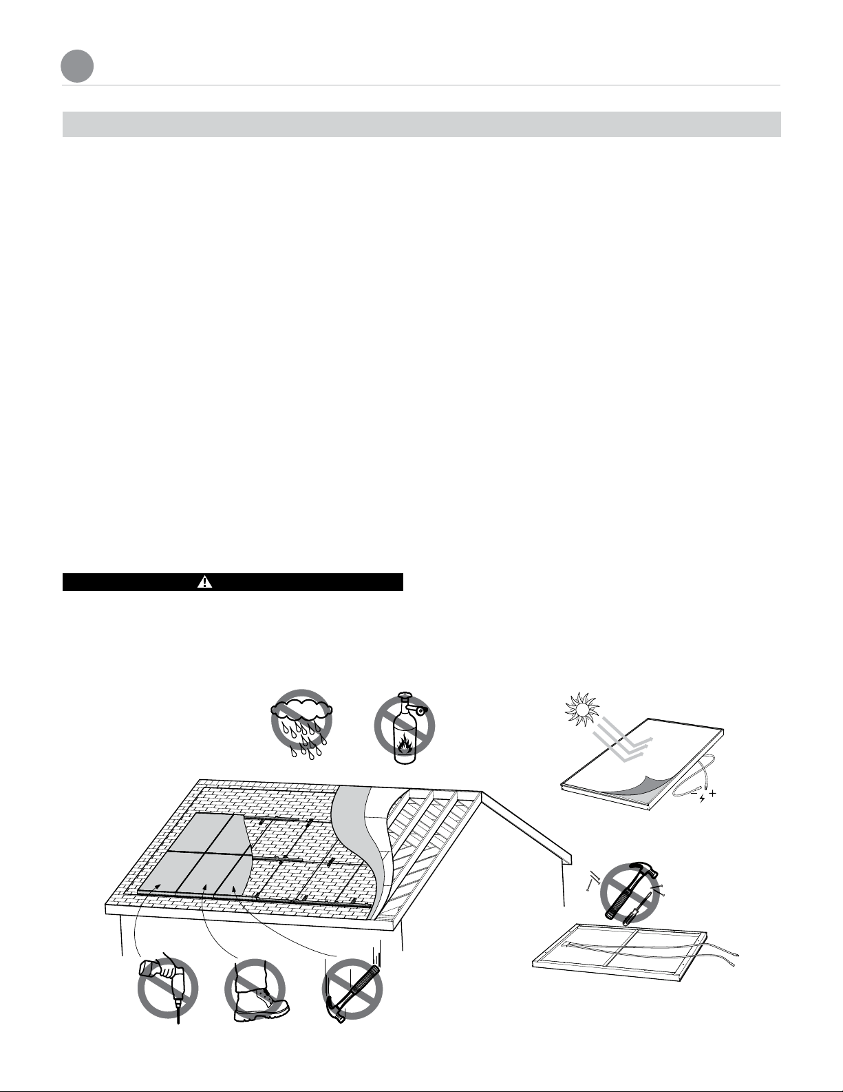
• When it is raining, or there is a strong probability
that it will start raining.
• Immediately after rain, and when work areas are
slippery.
• When high wind conditions exist, or are expected,
or when a high wind warning has been issued.
• When it is snowing, or when there is snow
underfoot.
• When the condition of the scaffolding and ladders
is not satisfactory.
3 Wear appropriate work clothes and protective
equipment.
• Work clothes for both the upper and lower body
should fit well and allow you to move freely.
• Always wear protective equipment such as
harnesses and lifelines.
• Wear a helmet and secure it correctly.
• Wear non-slip shoes. Shoes get dirty when worn
on a roof, so keep the soles clean.
4 Observe safety regulations for ascending and
descending ladders and stepladders.
• Before use, always inspect ladders and stepladders
to makes sure they are in good condition.
1.2 SRS MOUNTING SYSTEM
• Choose a safe spot to anchor ladders and
stepladders.
• Always work with a partner. One person should
hold the ladder steady.
• Ladders from a first-story roof to a second-story
roof are very dangerous. Do not set up a ladder
on a roof. When there is no other choice, straddle
the ridge and lay down a rubber anchor mat, and
secure the ladder to the mat. Always have one
person hold the ladder firmly.
• When you use a two-stage ladder, secure it with
ropes or stays to prevent it from sliding sideways,
and have two people hold the ladder steady.
• Use ladders with steps broad enough to permit
safe work.
5 When working in high places, wear harnesses and
use scaffolding.
• When working at heights of 6 feet or more, use
scaffolds or other equipment to ensure a stable
work platform.
• Scaffolds should be designed and erected by a
qualified person.
• When it is difficult to erect a stable work platform,
install safety nets, wear harnesses, and take other
measures to prevent falls.
• Regulations mandate the use of harnesses. Fasten
harnesses securely, and check that the length of
lifelines is 6 feet or less.
• Attach the primary support line securely to a
metal fixture installed for that purpose on a ridge
or beam.
6 Install enclosures and covers.
• Install enclosures, guardrails, or covers at the end of
work decks that are 10 feet or more above ground,
at openings, and at other dangerous locations.
• When it is extremely difficult to install enclosures,
guardrails, or covers, or when they must be
removed to work in that location, install a safety
net, wear harnesses, and take other measures to
prevent falls.
1FOR SAFE INSTALLATION WORK
7

7 Protect against falling objects.
• When objects are thrown down from a height of
6 ft or more, appoint a surveillance person on the
ground and warn others about falling objects.
• Do not allow third parties to enter the work area
during construction.
• Arrange tools and materials neatly and secure
them with ropes, or use bags or other measures to
prevent falling objects.
8 Other
• When there are electric power lines near the roof
or eaves, request the power utility to take advance
measures to prevent shock.
• Check the health of workers before starting work.
• Lift packaged modules by grasping both sides of
the package. Do not lift by grasping the band, as
the band can break.
• Never step or sit on the glass surface of a solar
module.
WARNING
Wiring work should be performed
according to the provisions of the National Electrical
Code. Grounding work and wiring connections to
the inverter should be performed by a qualified
electrician.
Adhere to all of the NEC. Pay special attention to
Article 110, Chapter 2 , Article 250, Chapter 3, Articles
300 & 310, 480 & 690.
The solar array generates electricity whenever it is
exposed to sunlight. Be careful when handling it. There is
a danger of shock if you touch the connectors or wires of
the electric cables.
1 Points to check before wiring.
• The solar modules generate electricity when
exposed to light. You will need to wear insulating
gloves.
• You will need a multimeter for volts, amps,
resistance and continuity capable of measuring
DC and AC up to 600 Volts and 40 Amps.
• Make sure your tools are insulated.
2 Wiring the solar modules.
• Never step or sit on the glass surface of the solar
modules. The glass may break.
• When you install the solar modules on the rail, never
allow an output cable to become caught between
the rail and a module frame.
• The solar modules generate electricity when
exposed to sunlight, take care not to short circuit
the output cables. The cables can become
overheated and their cable sheaths can melt.
• Ensure the module connectors are fully inserted.
There is a risk of malfunction if they are not pushed
in all the way.
• Support output cables so that there is no slack.
High winds can blow slack cable against the rail,
damaging the cables.
3 Wiring from solar arrays to the inverter (connector
box).
• Follow the provisions of the National Electrical
Code. Adhere to all of the NEC. Pay special
attention to Article 110, Chapter 2, Article 250,
Chapter 3, Articles 300 & 310, 480 & 690.
• For wiring through walls, protect the cables with
metal conduits, flexible metal conduits, or other
protection. Failure to do so can result in shock
and short circuits. Always use conduit to protect
sections of array output cables that are exposed
to sunlight.
For wiring outdoors, protect cables with PVC
conduits, metal conduits or flexible conduits.
• Prevent water from entering or building up in
conduit by using waterproof fittings or duct seal.
• To prevent shock, tape and label the cut ends of
array output extension cables (the side opposite
to the connector side) before connecting to solar
module output cables. Further, tape them again
after measuring the voltage of each array.
• To prevent shock when you connect the array
output cables to the inverter, remove the tape one
cable at a time as you connect the cables.
1.3 PV MODULES
8
1FOR SAFE INSTALLATION WORK

9
2POINTS TO CHECK WHEN SELECTING THE INSTALLATION LOCATION
• Check the following items before starting installation work.
• Refer to the inverter installation manual for more information about inverter installation and electrical work.
2.1 CONDITION OF HOUSE WHERE SOLAR POWER SYSTEM IS TO BE INSTALLED
INSPECTION OF ROOF STRUCTURE
It is important to inspect the structural integrity of the
roof and the durability of the roof materials. The SRS
mounting system and solar modules require a strong base
for durable and reliable operation in local environments.
Always wear a safety harness when working on the roof.
Inspect the roof surface in the area of the installation for
cracks, water leakage, and roofing material quality and
uniformity. This is especially important if the roof is older
than 10 years.
Inspect the roof for sags and other abnormalities. A sag
or deep depression in the roof may indicate a structural
weakness in the support system that may require
correction. The following illustrations detail typical roof
construction as well as old roof problems.
INSPECTION OF THE ROOF SUPPORT SYSTEM
This may require access to the attic.
Check that all rafters, trusses and other materials are in
good condition.
Check for indication of previous water leaks.
Measure the spacing of the rafters or trusses to confirm
the dimensions and prepare for the system layout.
Determine the location of the electrical roof penetration
and wire run, if wiring is planned for this area.
4Measuring array output voltage
• See the description of how to measure the output
voltage for each array.
• Make sure that all solar modules are exposed to
sunlight. (Remove lightproof sheets, if present.)
• Set the volt meter measurement range to a DC
voltage, greater than the expected measurement
(for example 600 VDC).
• Keep the plus (+) solar array output cables away
from the ends of the minus (-) cables. Dangerous
arcs can occur. (The array output voltage under
normal conditions (clear skies) can be very high.)
5 Grounding the mount
• To prevent shock, always connect a ground wire
from the SRS mounting system to earth.
• Use a minimum #10 AWG ground wire.
• Follow NEC 690 grounding provisions.
1FOR SAFE INSTALLATION WORK

EXAMPLES OF POOR ROOF CONDITION
Broken shingles
and sagging roof
Damaged
shingles
EXAMPLE ROOF CONSTRUCTION
Asphalt shingles
Roofing-felt
Roofing deck
Facia board
Rafters
Rake
Ridge
1 0
2POINTS TO CHECK WHEN SELECTING THE INSTALLATION LOCATION

1 1
2.2 CHECKING THE SOLAR POWER SYSTEM INSTALLATION LOCATION
CODE COMPLIANT INSTALLATION
1. Determine the wind loads for the installation site.
Check with your local building and safety department
for the specific requirements.
2. Make certain that the roof structure can support the
live and dead loads resulting from the installation of
the PV array.
3. Consult with a professional engineer if additional
assistance is required.
4. Determine the basic wind speed from the IBC wind
speed chart (for US locations).
5. Determine the exposure category A through D (obtain
latest definitions from IBC or local building code).
6. Determine total pressure by compiling basic wind
speed, exposure and roof height. Check with Sharp
technical support if your total pressure exceeds 45 PSF.
7. Reference the chart wind speeds to determine your
design wind pressure (PSF). Determine exposure
categories A through D for various roof heights.
8. Based on the loading in step 7, make certain that the
roof structure can support the load.
9. The modules and system are UL listed to standard
1703. The UL 1703 test is performed at 1.5 times the
design load of 30 lbs per square foot, or 45 lbs per
square foot. The system has been load tested by
Sharp to 50 PSF. Building departments often require
a design safety factor of 1.5 or greater for structures.
The maximum structural loading listed in this guide
does not include an added safety factor.
10.To achieve maximum load capacity, use at least
the same number of sliders as modules on each rail.
BASIC WIND SPEED SPECIFIED BY IBC
IBC Wind Speed Chart
90 (40)
90 (40)
90 (40)
90 (40)
90 (40)
100 (45)
100 (45)
100 (45)
100 (45)
110 (49)
110 (49)
110 (49)
110 (49)
120 (54)
120 (54)
120 (54)
120 (54)
130 (58)
130 (58)
130 (58)
130 (58)
130 (58)
140 (63)
140 (63)
140 (63)
140 (63)
140 (63)
140 (63)
140 (63)
150 (67)
150 (67)
150 (67)
Location V mph (m/s)
Hawaii 105 (47)
Puerto Rico 145 (65)
Guam 170 (76)
Virgin Islands 145 (65)
American Samoa 125 (56)
Notes:
1. Values are nominal design 3-second gust wind speeds in miles per hour (m/s)
at 33 ft. (10 m) above ground for Exposure C category.
2. Linear interpolation between wind contours is permitted.
3. Islands and coastal areas outside the last contour shall use the last wind speed
contour of the coastal area.
4. Mountainous terrain, gorges, ocean promontories, and special wind regions
shall be examined for unusual wind conditions.
2006 International Building Code - Basic Wind Speed (3-second gust)
2POINTS TO CHECK WHEN SELECTING THE INSTALLATION LOCATION

1. Install solar modules facing south, if possible. Installations facing east and west are also possible, although the amount
of power generated will be lower. Check the roof from a southern orientation, and check for obstacles that will
cast a shadow. These factors will lower the amount of power generated. Explain this to the users and obtain their consent.
2. Install in a location that has good sun exposure throughout the year. Less power is generated in shaded locations.
3. Check the following before installation.
3.1 Solar modules should not be installed within 12" from the ridge or edges of the roof, nor within 16" from the eave.
3.2 Installation is not possible in regions where the wind pressure exceeds 45 PSF. Check with your local building
department to determine if this mounting system is in compliance. Installation is not recommended when the
roof angle is less that 10 degrees or greater than 45 degrees.
3.3 Installation is not possible in the peripheral shaded area of the following figure.
3.4 Do not locate systems near coastal locations or other salt water locations or C5 locations as classified by ISO.
Minimum distance is 0.3 miles from the body of water. Do not locate in a corrosion prone area.
4. The array must be installed at least 16" away from the eave of the roof and 12" from the sides of the roof. This border
will enhance the wind load resistance of the system. Measure the perimeter of the roof surface where the array will be
installed.
16" min.
12" min.
12" min.
12" min.
SOLAR MODULES
CAN NOT BE
LOCATED IN
SHADED AREA
5. The output of a series string of solar modules is connected to the input of the inverter. Always install solar modules so
that all elements of the array receive the same amount of sunlight.
The amount of power generated declines dramatically if you connect solar modules receiving different amounts of
light in a string array, for example, solar modules facing east and solar modules facing south should not be connected
in the same string.
Refer to the inverter installation manual for more information about the number of solar modules connected in series
in a single array.
6. It may not be possible to install solar modules in the following areas and under the following conditions. For more
information, contact technical support.
• Regions with heavy snowfall - Installation is not possible in regions where maximum snow accumulation exceeds
the maximum allowable load. Contact the building & safety department for more information about maximum
snow accumulation.
1 2
2POINTS TO CHECK WHEN SELECTING THE INSTALLATION LOCATION

1 3
3SPECIFICATIONS
3.1 SOLAR MODULE AND ARRAY SPECIFICATIONS MODULES: ND-187U1, ND-187U1F, ND-167U1Y
1 Array specifications (typical examples)
Array: Layout of series connected solar modules
ND-187U1 ND-167U1Y
Quantity of Solar modules 18 20 24 27 18 20 24 27
Solar power capacity (kW) STC 3.4 3.74 4.5 5.0 3.0 3.3 4.0 4.5
Solar module area (sq.ft.) 284.9 316.6 379.9 427.4 255.8 284.2 341.0 383.7
2 Individual specifications and dimensions
ND-187U1 ND-187U1F ND-167U1Y
Power (W) STC 187 187 167
Max. power voltage (V) 25.6 25.8 22.97
Max. power current (A) 7.31 7.25 7.27
Open circuit voltage (V) 32.5 32.7 29.04
Short-circuit current (A) 8.13 7.99 8.02
Weight (lbs) 39.6 39.6 35.27
Dimensions (in) 58.7 x 39.1 x 2.26 52.3 x 39.1 x 2.26
Rated electrical characteristics are within ±10 percent of the indicated values of Isc and Voc and within +10/-5 percent of
Pmax under standard test conditions (irradiance of 100 mW/cm2, AM 1.5 spectrum, and a cell temperature of 25˚C (77°F)).
Under normal conditions, a photovoltaic module may experience conditions that cause more current and/or voltage than
reported at Standard Test Conditions. Accordingly, the values of Isc and Voc marked on UL Listed modules should be
multiplied by a factor of 1.25 when determining component voltage ratings, conductor capacities, fuse sizes and size of
controls connected to the module output. Refer to Sec. 690-8 of the National Electric Code for an additional multiplying
factor of 125 percent which may be applicable. In the coverage of Canadian UL listing, installation shall be in accordance
with CSA C22.1, Safety Standard for Electrical Installations, Canadian Electrical Code, Part 1.
SOLAR MODULE
- (negative) waterproof connector
+ (positive) waterproof
connector
- (negative) output cable
+ (positive) output cable
Frame
Terminal box
Solar cell
Clear tempered glass
58.3"*
52.3"**
39.1"
* ND-187U1, ND-187U1F
** ND-167U1Y

3.2 ND-187U1, ND-187U1F, ND-167U1Y MODULE ARRAY LAYOUT DIMENSIONS
The location of the mounting feet and rails is dependent on the layout of the array. Use the following grid to determine
the overall size of the array that will fit on the installation location.
Maximum module layout (shown) is 16 wide x 6 tall.Contact Sharp for other configurations.
* ND-187U1, ND-187U1F
** ND-167U1Y
39 1/8" 78 1/4" 117 3/8" 156 1/2" 195 5/8" 234 3/4" 273 7/8" 313" 352 1/8" 391 1/4" 430 3/8" 469 1/2" 508 5/8" 547 3/4" 586 7/8"
626”
58 7/8"*
52 7/16"**
Eave cover
1 5/8"
117 3/4"*
104 15/16 "**
176 5/8"*
157 3/8"**
235 1/2"*
157 3/8"**
294 3/8"*
209 13/16"**
Ridge cover 1 5/8"
353 1/4"*
262 1/4"**
3SPECIFICATIONS
1 4

1 5
4PARTS
1 5
STANDARD PARTS
Part No. AD804 XA52 AD801 AD105
Model name Dock washer M8 Bolt 20
(shown appx. size)
Module mounting clip Threaded tab
Dimensions M8 x 20 mm
Material Anti-corrosion
coated steel
Stainless steel Anti-corrosion
coated steel
Anti-corrosion
coated steel
Part No. AD101 AD802 XA05
Model name Splice Side cover M4 Side cover screw
(shown appx. size)
Dimensions M4 x 12 mm
Material Anti-corrosion coated
steel
Aluminum Stainless steel
Part No. AA801 AA802 AA803 AA804
Model name Rail 1 in 1 Rail 2 in 1 Rail 3 in 1 Rail 4 in 1
Dimensions Length: 35.98" Length: 75.12" Length: 114.25" Length: 153.39"
Material Anti-corrosion coated steel
Part No. AA805 AB801 AB802 AB803
Model name Rail 1.5 in 1 Front cover Front cover, half size Front cover with
Sharp logo
Dimensions Length: 55.55" Length: 39.13" Length: 19.57" Length: 39.13"
Material Anti-corrosion coated
steel Aluminum

4PARTS
1 61 6
ROOF TILE PARTS
Part No. AE112 AE105 AE106 AE107
Model name Roof tile drill bit per piece
(6 pcs/case)
Tile roof bottom butyl
pad
Tile roof top butyl pad
assy
Silicone caulking
Material Butyl rubber Anti-corrosion
coated steel
Silicone
Part No. AE110 AK111 AE104 AE102
Model name Tile roof slider Support AL plate Tile roof stand off Tile roof slider bracket
Material Anti-corrosion
coated steel
Aluminum Anti-corrosion
coated steel
Anti-corrosion
coated steel
Part No. XA27 XA02
Model name Support AL screw 5.5 x 35
(shown appx. size)
Standard slider mounting screw 5.5 x 80
(shown appx. size)
Material Stainless steel
Part No. XA50
Model name Tile roof stand off screw 5.5 x 135
(shown appx. size)
Material Stainless steel

1 7
ASPHALT ROOF PARTS
Part No. AS801 AS804 AS105 AD805
Model name Standard slider
assembly
Mounting Flash
assembly
Standard slider bottom
bracket
Standard slider top
bracket
Dimensions 11" x 2" x 1" 14" x 10" x 1.25"
Material Anti-corrosion coated steel Anti-corrosion coated steel
Part No. AE107 XA02
Model name Silicone caulking Standard slider mounting screw 5.5 x 80
(shown appx. size)
Material Silicone Stainless steel
Part No. XA58
Model name Standard slider mounting screw w/ flashing 5.5 x 110
(shown appx. size)
Material Stainless steel
4PARTS

4PARTS
1 8
OPTIONAL PARTS
Part No. AD803 AD806 AE107
Model name Cable support bar Cable clip Silicone caulking
Material Stainless steel Anti-corrosion coated steel Silicone
Part No. AK113 AK114 XA53
Model name 0.1" shim 0.4" shim M8 Bolt 30
(shown appx. size)
Dimensions M8 x 30 mm
Material Anti-corrosion coated steel Stainless Steel
Part No. XA54 XA55
Model name M8 Bolt 40
(shown appx. size)
M8 Bolt 50
(shown appx. size)
Dimensions M8 x 40 mm M8 x 50 mm
Material Stainless Steel
Part No. XA56 XA57
Model name M8 Bolt 60
(shown appx. size)
M8 Bolt 70
(shown appx. size)
Dimensions M8 x 60 mm M8 x 70 mm
Material Stainless Steel

TECH NOTE
Anti-corrosion coated steel is steel coated
with a layer consisting primarily of zinc
plus another metal, such as aluminum or
magnesium.
After it is cut, mild corrosion develops initially
at the cut surface, but then the components
of the coating layer dissolve to form a stable
protective layer over the cut.
Cut surface
Thin oxidation Fine-grained
protective layer
Coated layer
Coated layer
Coated layer
Coated layer
Oxidation
becomes less
prominent.
5POINTS TO CHECK BEFORE INSTALLATION WORK
WARNING
• The solar modules generate electricity when exposed to sunlight, so be careful not to short circuit the output cables.
If shorted, the cables can become overheated and their cable sheaths can melt.
• Stop working when the surface of the roof is wet. There is a danger of slipping, falling, and shock.
CAUTION
• Never step or sit on the glass surface of the solar modules. The glass may break.
• Do not twist the solar modules when you mount them (twisting should not exceed 0.1" per 4"). Failures and damage
can result.
• When you mount the solar modules on the rail, never allow an output cable to become caught between the rail and a
module frame. Short circuits and fire can result.
5.1 UNPACKING AND CHECKING PARTS
When you unpack the system, check the model names of the components of each system and check to be sure that you
have the correct number of parts.
5.2 MATERIALS AND TOOLS YOU WILL NEED
Before starting installation work, make sure you have the following materials and tools on hand (including materials and
tools for electrical work).
Suggested Materials
Ground wire Ground rod Electrical
tape
Flexible
metal conduit
(to protect
electric cables)
Cable ties Pencil
1 91 9
4PARTS

2 0
Tools
Cordless drill Socket drivers
8 mm & 13 mm
Phillips driver bits Drill Screw driver set
Needle nose pliers Line man’s pliers Wire cutters Hammer Chisel
Crimping tool Knife Tape measure Extension cord Chalk line
Gloves & safety
helmet
Rope Tool belt Ladders Safety Harness
Safety glasses Air mask Ratchet Wrench
13 mm
8 mm
Measurement
Compass Calculator Solar insolation meter Digital multimeter
5POINTS TO CHECK BEFORE INSTALLATION WORK
Table of contents
Other Sharp Inverter manuals
Popular Inverter manuals by other brands

Generac Power Systems
Generac Power Systems PWRcell XVT076A03 Installation and owner's manual

Strend Pro
Strend Pro RY-WT8C58-C instruction manual

Delios
Delios DLS 300C installation guide

Xantrex
Xantrex Fleet Power FP 3000-12 owner's manual

Fusion
Fusion 782-2234 owner's manual

CPS
CPS SCA23KTL-DO/US-480 Installation and operation manual