6
R-509FW
OPERATION
DESCRIPTION OF OPERATING SEQUENCE
Thefollowingisadescriptionofcomponentfunctionsduring
oven operation.
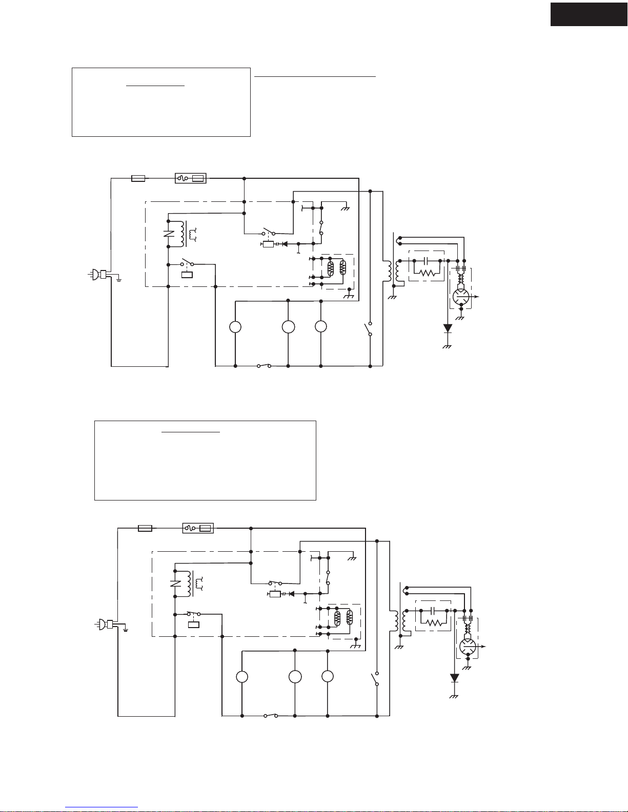
OFF CONDITION
Closing the door activates the door sensing switch and
primaryinterlockswitch.(Inthiscondition,themonitorswitch
contactsareopened.)
When oven is plugged in, 120 volts A.C. is supplied to the
control unit. (Figure O-1).
1. Thedisplaywillshowflashing"88:88".
Tosetanyprogramorsettheclock,youmustfirsttouch
theSTOP/CLEAR pad. The display will clear, and " : "
will appear.
COOKING CONDITION
Program desired cooking time by touching the NUMBER
pads. Program the power level by touching the POWER
LEVEL pad and then a Number pad.
When the START pad is touched, the following operations
occur:
1. The contacts of relays are closed and components
connected to the relays are turned on as follows.
(For details, refer to Figure O-2)
RELAY CONNECTED COMPONENTS
RY-1 oven lamp/turntable motor/fan motor
RY-2 power transformer
2. 120 volts A.C. is supplied to the primary winding of the
power transformer and is converted to about 3.3 volts
A.C. output on the filament winding, and approximately
2370 volts A.C. on the high voltage winding.
3. Thefilamentwindingvoltageheatsthemagnetronfilament
andtheH.V.windingvoltageissentto avoltagedoubler
circuit.
4. The microwave energy produced by the magnetron is
channelled through the waveguide into the cavity feed-
box, and then into the cavity where the food is placed to
be cooked.
5. Upon completion of the cooking time, the power
transformer, oven lamp, etc. are turned off, and the
generation of microwave energy is stopped. The oven
will revert to the OFF condition.
6. Whenthedoorisopenedduringacookcycle,themonitor
switch, door sensing switch, primary interlock switch,
relay (RY1) and secondary interlock relay are activated
with the following results. The circuits to the turntable
motor, the cooling fan motor, and the high voltage
componentsarede-energized,theovenlampremainson,
andthedigitalread-outdisplaysthetimestillremainingin
the cook cycle when the door was opened.
7. Themonitorswitchelectricallymonitorstheoperationof
theprimaryinterlockswitchandsecondaryinterlockrelay
andismechanicallyassociatedwiththedoorsothatitwill
functioninthefollowingsequence.
(1) When the door opens from the closed position, the
secondary interlock relay (RY2) and primary interlock
switch open their contacts. And contacts of the relay
(RY1)remainsclosed.Thenthemonitorswitchcontacts
close.
(2) When the door is closed from the open position, the
monitor switch contacts open first. Then the contacts of
the primary interlock switch and door sensing switch
close. And contacts of the relay (RY1) open.
Iftheprimaryinterlockswitchand secondaryinterlockrelay
(RY2)failwiththecontactsclosedwhenthedoorisopened,
the closing of the monitor switch contacts will form a short
circuit through the C/T fuse, primary interlock switch, relay
(RY1)andsecondaryinterlockrelay(RY2),causingtheC/T
fuse to blow.
POWER LEVEL P-0 TO P-90 COOKING
WhenVariableCookingPowerisprogrammed,the120volts
A.C. is supplied to the power transformer intermittently
throughthecontactsofrelay(RY-2)whichisoperatedbythe
controlunitwithina32secondtimebase.Microwavepower
operation is as follows:
VARI-MODE ON TIME OFF TIME
Power 10(P-HI) 32 sec. 0 sec.
(100% power)
Power 9(P-90) 30 sec. 2 sec.
(approx. 90% power)
Power 8(P-80) 26 sec. 6 sec.
(approx. 80% power)
Power 7(P-70) 24 sec. 8 sec.
(approx. 70% power)
Power 6(P-60) 22 sec. 10 sec.
(approx. 60% power)
Power 5(P-50) 18 sec. 14 sec.
(approx. 50% power)
Power 4(P-40) 16 sec. 16 sec.
(approx. 40% power)
Power 3(P-30) 12 sec. 20 sec.
(approx. 30% power)
Power 2(P-20) 8 sec. 24 sec.
(approx. 20% power)
Power 1(P-10) 6 sec. 26 sec.
(approx. 10% power)
Power 0(P-0) 0 sec. 32 sec.
(0% power)
Note: TheON/OFFtimeratiodoesnotcorrespondwiththe
percentageofmicrowavepower,becauseapprox.2
seconds are needed for heating of the magnetron
filament.