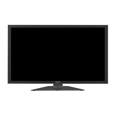
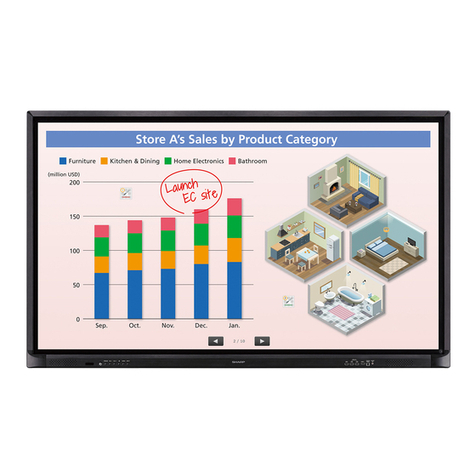
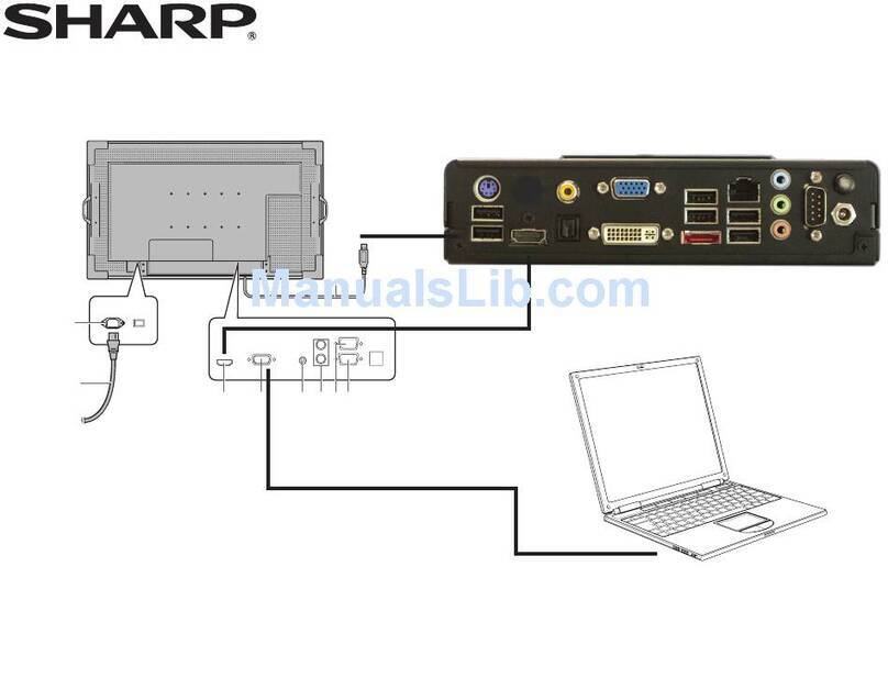
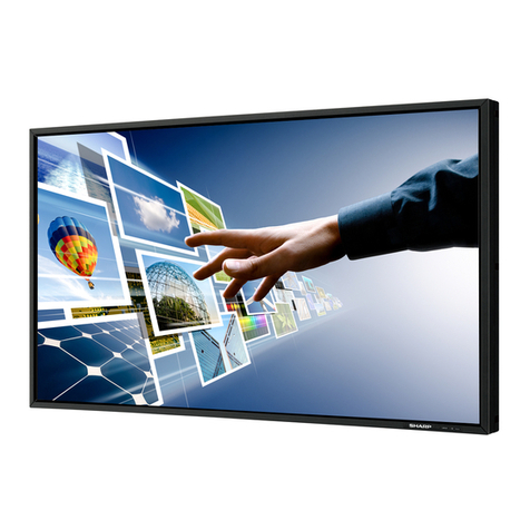
Sharp PN-L602B User manual

PN-L602B
LCD MONITOR
OPERATION MANUAL

IMPORTANT:
To aid reporting in case of loss or theft, please record the
product’s model and serial numbers in the space provided.
The numbers are located in the rear of the product.
Model No.:
Serial No.:
U.S.A. ONLY
FOR CUSTOMERS IN U.K.
IMPORTANT
The wires in this mains lead are coloured in accordance with the following code:
GREEN-AND-YELLOW: Earth
BLUE: Neutral
BROWN: Live
As the colours of the wires in the mains lead of this apparatus may not correspond with the coloured markings identifying the
terminals in your plug proceed as follows:
•ThewirewhichiscolouredGREEN-AND-YELLOWmustbeconnectedtotheterminalintheplugwhichismarkedbythe
letter Eor by the safety earth orcolouredgreenorgreen-and-yellow.
•ThewirewhichiscolouredBLUEmustbeconnectedtotheterminalwhichismarkedwiththeletterNor coloured black.
•ThewirewhichiscolouredBROWNmustbeconnectedtotheterminalwhichismarkedwiththeletterLor coloured red.
Ensurethatyourequipmentisconnectedcorrectly.Ifyouareinanydoubtconsultaqualiedelectrician.
“WARNING: THIS APPARATUS MUST BE EARTHED.”

3E
IMPORTANT INFORMATION
WARNING: TOREDUCETHERISKOFFIREORELECTRICSHOCK,DONOTEXPOSETHISPRODUCT
TORAINORMOISTURE.
RISKOFELECTRIC
SHOCK
DONOTOPEN
CAUTION
CAUTION: TOREDUCETHERISKOFELECTRIC
SHOCK,DONOTREMOVECOVER.
NOUSER-SERVICEABLEPARTS
INSIDE.
REFERSERVICINGTOQUALIFIED
SERVICEPERSONNEL.
Thelightningashwitharrowheadsymbol,within
anequilateraltriangle,isintendedtoalertthe
user to the presence of uninsulated “dangerous
voltage” within the product’s enclosure that may
beofsufcientmagnitudetoconstituteariskof
electric shock to persons.
The exclamation point within a triangle is
intended to alert the user to the presence of
important operating and maintenance (servicing)
instructions in the literature accompanying the
product.
WARNING:
FCCRegulationsstatethatanyunauthorizedchangesormodicationstothisequipmentnotexpresslyapprovedbythe
manufacturercouldvoidtheuser’sauthoritytooperatethisequipment.
NOTE:
ThisequipmenthasbeentestedandfoundtocomplywiththelimitsforClassAdigitaldevice,pursuanttoPart15ofthe
FCCRules.Theselimitsaredesignedtoprovidereasonableprotectionagainstharmfulinterferencewhentheequipment
isoperatedinacommercialenvironment.Thisequipmentgenerates,uses,andcanradiateradiofrequencyenergyand,if
not installed and used in accordance with the instruction manual, may cause harmful interference to radio communications.
Operationofthisequipmentinaresidentialareaislikelytocauseharmfulinterferenceinwhichcasetheuserwillberequired
to correct the interference at his own expense.
ThisproductutilizesaCRcoinLithiumbatterywhichcontainsaPerchloratematerial.
Special handling for this material may apply,
Californiaresidents,Seewww.dtsc.ca.gov/hazardouswaste/perchlorate/
Others,consultlocalenvironmentalofcers.
U.S.A. ONLY

4
E
IMPORTANT INFORMATION (Continued)
A. Information on Disposal for Users (private households)
1. In the European Union
Attention:Ifyouwanttodisposeofthisequipment,pleasedonotusetheordinarydustbin!
Usedelectricalandelectronicequipmentmustbetreatedseparatelyandinaccordancewithlegislationthatrequiresproper
treatment,recoveryandrecyclingofusedelectricalandelectronicequipment.
Followingtheimplementationbymemberstates,privatehouseholdswithintheEUstatesmayreturntheirusedelectricaland
electronicequipmenttodesignatedcollectionfacilitiesfreeofcharge*.Insomecountries*yourlocalretailermayalsotake
back your old product free of charge if you purchase a similar new one.
*)Pleasecontactyourlocalauthorityforfurtherdetails.
Ifyourusedelectricalorelectronicequipmenthasbatteriesoraccumulators,pleasedisposeoftheseseparatelybeforehand
accordingtolocalrequirements.
Bydisposingofthisproductcorrectlyyouwillhelpensurethatthewasteundergoesthenecessarytreatment,recoveryand
recycling and thus prevent potential negative effects on the environment and human health which could otherwise arise due
to inappropriate waste handling.
2. In other Countries outside the EU
If you wish to discard this product, please contact your local authorities and ask for the correct method of disposal.
ForSwitzerland:Usedelectricalorelectronicequipmentcanbereturnedfreeofchargetothedealer,evenifyoudon’t
purchaseanewproduct.Furthercollectionfacilitiesarelistedonthehomepageofwww.swico.chorwww.sens.ch.
B. Information on Disposal for Business Users
1. In the European Union
If the product is used for business purposes and you want to discard it:
PleasecontactyourSHARPdealerwhowillinformyouaboutthetake-backoftheproduct.Youmightbechargedforthe
costsarisingfromtake-backandrecycling.Smallproducts(andsmallamounts)mightbetakenbackbyyourlocalcollection
facilities.
ForSpain:Pleasecontacttheestablishedcollectionsystemoryourlocalauthorityfortake-backofyourusedproducts.
2. In other Countries outside the EU
If you wish to discard of this product, please contact your local authorities and ask for the correct method of disposal.
Attention: Your product is marked with this symbol. It means that used electrical and electronic products
should not be mixed with general household waste. There is a separate collection system for these products.
The battery supplied with this product contains traces of Lead.
ForEU:
Thecrossed-outwheeledbinimpliesthatusedbatteriesshouldnotbeputtothegeneralhousehold
waste!Thereisaseparatecollectionsystemforusedbatteries,toallowpropertreatmentandrecyclingin
accordance with legislation. Please contact your local authority for details on the collection and recycling
schemes.
ForSwitzerland:
The used battery is to be returned to the selling point.
Forothernon-EUcountries:
Please contact your local authority for correct method of disposal of the used battery.
“BATTERYDISPOSAL”
THISPRODUCTCONTAINSALITHIUMPRIMARY(MANGANESSDIOXIDE)MEMORYBACK-UPBATTERYTHAT
MUSTBEDISPOSEDOFPROPERLY.PLEASECONTACTYOURLOCALSHARPDEALERORAUTHORIZEDSERVICE
REPRESENTATIVEFORASSISTANCEINDISPOSINGOFTHISBATTERY.
U.S.A.ANDCANADAONLY
EUONLY
EUONLY

5E
ThankyouforyourpurchaseofaSHARPLCDproduct.Toensuresafetyandmanyyearsoftrouble-freeoperationofyour
product, please read the Safety Precautions carefully before using this product.
SAFETY PRECAUTIONS
Electricityisusedtoperformmanyusefulfunctions,butitcanalsocausepersonalinjuriesandpropertydamageifimproperly
handled.Thisproducthasbeenengineeredandmanufacturedwiththehighestpriorityonsafety.However,improperusecan
resultinelectricshockand/orre.Inordertopreventpotentialdanger,pleaseobservethefollowinginstructionswheninstalling,
operatingandcleaningtheproduct.ToensureyoursafetyandprolongtheservicelifeofyourLCDproduct,pleasereadthe
following precautions carefully before using the product.
1. Readinstructions—Alloperatinginstructionsmustbereadandunderstoodbeforetheproductisoperated.
2. Keepthismanualinasafeplace—Thesesafetyandoperatinginstructionsmustbekeptinasafeplaceforfuture
reference.
3. Observewarnings—Allwarningsontheproductandintheinstructionsmustbeobservedclosely.
4. Followinstructions—Alloperatinginstructionsmustbefollowed.
5. Cleaning—UnplugthepowercordfromtheACoutletbeforecleaningtheproduct.Useadryclothtocleantheproduct.Do
notuseliquidcleanersoraerosolcleaners.
6. Attachments—Donotuseattachmentsnotrecommendedbythemanufacturer.Useofinadequateattachmentscanresult
in accidents.
7. Waterandmoisture—Donotusetheproductnearwater.Donotinstalltheproductinaplacewherewatermaysplashonto
it.Becarefulofequipmentwhichdrainswatersuchasanair-conditioner.
8. Ventilation—Theventsandotheropeningsinthecabinetaredesignedforventilation.
Donotcoverorblocktheseventsandopeningssinceinsufcientventilationcancauseoverheatingand/orshortenthelife
oftheproduct.Donotplacetheproductonasofa,rugorothersimilarsurface,sincetheycanblockventilationopenings.
Donotplacetheproductinanenclosedplacesuchasabookcaseorrack,unlessproperventilationisprovidedorthe
manufacturer’s instructions are followed.
9. Powercordprotection—Thepowercordsmustberoutedproperlytopreventpeoplefromsteppingonthemorobjectsfrom
resting on them.
10. Thescreenusedinthisproductismadeofglass.Therefore,itcanbreakwhentheproductisdroppedorappliedwith
impact.Becarefulnottobeinjuredbybrokenglasspiecesincasethescreenbreaks.
11. Overloading—DonotoverloadACoutletsorextensioncords.Overloadingcancausereorelectricshock.
12. Enteringofobjectsandliquids—Neverinsertanobjectintotheproductthroughventsoropenings.Highvoltageowsin
theproduct,andinsertinganobjectcancauseelectricshockand/orshortinternalparts.
Forthesamereason,donotspillwaterorliquidontheproduct.
13. Servicing—Donotattempttoservicetheproductyourself.Removingcoverscanexposeyoutohighvoltageandother
dangerousconditions.Requestaqualiedservicepersontoperformservicing.
14. Repair—Ifanyofthefollowingconditionsoccurs,unplugthepowercordfromtheACoutlet,andrequestaqualiedservice
person to perform repairs.
a. Whenthepowercordorplugisdamaged.
b. Whenaliquidwasspilledontheproductorwhenobjectshavefallenintotheproduct.
c. Whentheproducthasbeenexposedtorainorwater.
d. Whentheproductdoesnotoperateproperlyasdescribedintheoperatinginstructions.
Donottouchthecontrolsotherthanthosedescribedintheoperatinginstructions.Improperadjustmentofcontrols
notdescribedintheinstructionscancausedamage,whichoftenrequiresextensiveadjustmentworkbyaqualied
technician.
e. Whentheproducthasbeendroppedordamaged.
f. Whentheproductdisplaysanabnormalcondition.Anynoticeableabnormalityintheproductindicatesthattheproduct
needs servicing.
15. Replacementparts—Incasetheproductneedsreplacementparts,makesurethattheservicepersonusesreplacement
partsspeciedbythemanufacturer,orthosewiththesamecharacteristicsandperformanceastheoriginalparts.Useof
unauthorizedpartscanresultinre,electricshockand/orotherdanger.
16. Safetychecks—Uponcompletionofserviceorrepairwork,requesttheservicetechniciantoperformsafetychecksto
ensure that the product is in proper operating condition.
17. Wallmounting—Whenmountingtheproductonawall,besuretoinstalltheproductaccordingtothemethod
recommended by the manufacturer.
18. Heatsources—Keeptheproductawayfromheatsourcessuchasradiators,heaters,stovesandotherheat-generating
products(includingampliers).
DEAR SHARP CUSTOMER

6
E
SAFETY PRECAUTIONS (Continued)
19. Batteries—Incorrectuseofbatteriesmaycausethebatteriestoburstorignite.Aleakybatterymaycorrodetheequipment,
dirty your hands or spoil your clothing. In order to avoid these problems, make sure to observe the precautions below:
•Usethespeciedbatteriesonly.
•Installthebatterieswithdueattentiontotheplus(+)andminus(-)sidesofthebatteriesaccordingtotheinstructionsinthe
compartment.
•Donotmixoldandnewbatteries.
•Donotmixbatteriesofdifferenttypes.Voltagespecicationsofbatteriesofthesameshapemayvary.
•Replaceanexhaustedbatterywithanewonepromptly.
•Ifyouwillnotusetheremotecontrolforalongtime,removethebatteries.
•Ifleakedbatteryuidgetsonyourskinorclothing,rinseimmediatelyandthoroughly.Ifitgetsintoyoureye,batheyour
eyewellratherthanrubbingandseekmedicaltreatmentimmediately.Leakedbatteryuidthatgetsintoyoureyeoryour
clothing may cause a skin irritation or damage your eye.
20. Usageofthemonitormustnotbeaccompaniedbyfatalrisksordangersthat,couldleaddirectlytodeath,personalinjury,
severe physical damage or other loss, including nuclear reaction control in nuclear facility, medical life support system, and
missile launch control in a weapon system.
21. Donotstayincontactwiththepartsoftheproductthatbecomehotforlongperiodsoftime.Doingsomayresultin
low-temperatureburns.
WARNING:
This is a class A product. In a domestic environment this product may cause radio interference in which case the user may be
requiredtotakeadequatecountermeasures.
TomaintaincompliancewithEMCregulations,useshieldedcablestoconnecttothefollowingterminals:PC/AVDVI-Doutput
terminal,PC/AVDVI-Dinputterminal,PC/AVHDMIinputterminal,PCD-SUBinputterminal,PCRGBinputterminals,and
RS-232Cinput/outputterminals.
Ifamonitorisnotpositionedinasufcientlystablelocation,itcanbepotentiallyhazardousduetofalling.Manyinjuries,
particularly to children, can be avoided by taking simple precautions such as:
•Usingxingdeviceslikewallmountbracketsrecommendedbythemanufacturer.
•Onlyusingfurniturethatcansafelysupportthemonitor.
•Ensuringthemonitorisnotoverhangingtheedgeofthesupportingfurniture.
•Notplacingthemonitorontallfurniture(forexample,cupboardsorbookcases)withoutanchoringboththefurnitureandthe
monitor to a suitable support.
•Notstandingthemonitorsonclothorothermaterialsplacedbetweenthemonitorandsupportingfurniture.
•Educatingchildrenaboutthedangersofclimbingonfurnituretoreachthemonitororitscontrols.
Especially for child safety
-Don’tallowchildrentoclimbonorplaywiththemonitor.
-Don’tplacethemonitoronfurniturethatcaneasilybeusedassteps,suchasachestofdrawers.
-Rememberthatchildrencanbecomeexcitedwhilewatchingaprogram,especiallyona“largerthanlife”monitor.Care
should be taken to place or install the monitor where it cannot be pushed, pulled over, or knocked down.
-Careshouldbetakentorouteallcordsandcablesconnectedtothemonitorsothattheycannotbepulledorgrabbedby
curious children.

7E
-TheTFTcolorLCDpanelusedinthismonitorismadewith
theapplicationofhighprecisiontechnology.However,there
may be minute points on the screen where pixels never light
or are permanently lit. Also, if the screen is viewed from
an acute angle there may be uneven colors or brightness.
Please note that these are not malfunctions but common
phenomenaofLCDsandwillnotaffecttheperformanceof
the monitor.
-Donotdisplayastillpictureforalongperiod,asthiscould
cause a residual image.
-Neverrubortapthemonitorwithhardobjects.
-PleaseunderstandthatSHARPCORPORATIONbearsno
responsibility for errors made during use by the customer or
a third party, nor for any other malfunctions or damage to this
product arising during use, except where indemnity liability is
recognizedunderlaw.
-Thismonitoranditsaccessoriesmaybeupgradedwithout
advance notice.
-Donotusethemonitorwherethereisalotofdust,where
humidity is high, or where the monitor may come into contact
withoilorsteam,asthiscouldleadtore.
-Ensurethatthemonitordoesnotcomeintocontactwith
waterorotheruids.Ensurethatnoobjectssuchaspaper
clipsorpinsenterthemonitorasthiscouldleadtoreor
electric shock.
-Donotplacethemonitorontopofunstableobjectsorin
unsafeplaces.Donotallowthemonitortoreceivestrong
shocksortostronglyvibrate.Causingthemonitortofallor
topple over may damage it.
-Donotusethemonitornearheatingequipmentorinplaces
where there is likelihood of high temperature, as this may
leadtogenerationofexcessiveheatandoutbreakofre.
-Donotusethemonitorinplaceswhereitmaybeexposedto
direct sunlight.
-TheACoutletshallbeinstalledneartheequipmentandshall
be easily accessible.
-DonottouchthescreenwhilethePCisstartingup,since
it will be detected as a failure of the infrared transmitter/
receiverelementsandwillleadtoamalfunction.Whenthis
occurs,restartthePC.
-Donotoperatethescreenwithahardorpointedobjectsuch
asangernail,pen,orpencil.
-Twotouchpanelscannotbeusedwhentwodisplaysare
connected to the computer.
Only the touch panel on the display that is set as the primary
monitor will be operable.
-IfanotherUSBdeviceisconnectedtothecomputertowhich
thetouchpanelisconnected,donotoperatetheUSBdevice
during touch panel input. Input may not take place correctly.
-Iftwotouchpanelsareusedincloseproximitytoeachother,
use handwriting mode. The touch pens will interfere with
each other and will not operate correctly.
-Iftheinfraredtransmitter/receiverbecomesdirty,
malfunctioning may result. Use a soft cloth to gently wipe dirt
off the infrared transmitter/receiver.
-Ifdustaccumulatesinsidetheinfraredtransmitter/receiver,
the product cannot transmit or receive infrared rays properly,
resulting in a malfunction. To clean the dust accumulated
inside,contactanauthorizedSHARPservicingdealeror
servicecenter(extrachargerequired).
The Power Cord
-Useonlythepowercordsuppliedwiththemonitor.
-Donotdamagethepowercordnorplaceheavyobjectson
it, stretch it or over bend it. Also, do not add extension cords.
Damagetothecordmayresultinreorelectricshock.
-Donotusethepowercordwithapowertap.
Addinganextensioncordmayleadtoreasaresultof
overheating.
-Donotremoveorinsertthepowerplugwithwethands.
Doingsocouldresultinelectricshock.
-Unplugthepowercordifitisnotusedforalongtime.
-Donotattempttorepairthepowercordifitisbroken
or malfunctioning. Refer the servicing to the service
representative.
Manual Scope
-Microsoft,Windows,WindowsVistaandInternetExplorer
areregisteredtrademarksofMicrosoftCorporation.
-HDMI,theHDMILogoandHigh-DenitionMultimedia
InterfacearetrademarksorregisteredtrademarksofHDMI
LicensingLLC.
-Adobe,Acrobat,andReaderareeitherregisteredtrademarks
or trademarks of Adobe Systems Incorporated in the United
States and/or other countries.
-Intel,Celeron,andIntelCore2Duoaretrademarksor
registeredtrademarksofIntelCorporationoritssubsidiaries
in the U.S.A. and other countries.
-AMD,AMDSempron,AMDAthlon,andcombinationsthereof
aretrademarksofAdvancedMicroDevices,Inc.
-ThisproductcomeswithRICOHBitmapFontsproducedand
soldbyRICOHCOMPANY,LTD.
-Allotherbrandandproductnamesaretrademarksor
registered trademarks of their respective holders.
-LanguageofOSDmenuusedinthismanualisEnglishby
way of example.
-Illustrationsinthismanualmaynotexactlyrepresentthe
actual product or display.
LED Backlight
● TheLEDbacklightinthisproducthasalimitedlifetime.
*Ifthescreengetsdarkordoesnotturnon,itmaybe
necessarytoreplacetheLEDbacklight.ThisLED
backlight is exclusive to this product and must be replaced
byanauthorizedSHARP servicing dealer or service
center.
*PleasecontactyourlocalSHARP servicing dealer or
service center for assistance.
TIPS AND SAFETY INSTRUCTIONS

8
E
MOUNTING PRECAUTIONS
• Thisproductisforuseindoors.
• AmountingbracketcompliantwithVESAspecicationsis
required.
• Sincethemonitorisheavy,consultyourdealerbefore
installing,removingormovingthemonitor.
• Mountingthemonitoronthewallrequiresspecialexpertise
andtheworkmustbeperformedbyanauthorizedSHARP
dealer.Youshouldneverattempttoperformanyofthis
workyourself.Ourcompanywillbearnoresponsibility
foraccidentsorinjuriescausedbyimpropermountingor
mishandling.
• Thismonitorcannotbeusedinverticalorientation.
• Usethemonitorwiththesurfaceperpendiculartoalevel
surface.Ifnecessary,themonitormaybetiltedupto20
degreesupward.
• Whenmovingthemonitor,besuretoholditwitheither
handlesorthecornersonthebottomoftheunit.Donot
placeyourhandonthescreen.Thismaycauseproduct
damage,failure,orinjury.
• Thismonitorshouldbeusedatanambienttemperature
between41°F(5°C)and95°F(35°C).Provideenough
spacearoundthemonitortopreventheatfrom
accumulatinginside.
7-7/8 [20]
Unit: inch [cm]
2 [5]
2
[5]
2
[5]
1-7/16 [3.5]
• Ifitisdifculttoprovidesufcientspaceforanyreason
suchastheinstallationofthemonitorinsideahousing,or
iftheambienttemperaturemaybeoutsideoftherange
of41°F(5°C)to95°F(35°C),installafanortakeother
measurestokeeptheambienttemperaturewithinthe
requiredrange.
• Temperatureconditionmaychangewhenusingthemonitor
togetherwiththeoptionalequipmentsrecommendedby
SHARP.Insuchcases,pleasecheckthetemperature
conditionspeciedbytheoptionalequipments.
• Donotblockanyventilationopenings.Ifthetemperature
insidethemonitorrises,thiscouldleadtoamalfunction.
• Donotplacethemonitoronadevicewhichgeneratesheat.
• Donotusetheproductinlocationswheretheunitis
exposedtodirectsunlightorotherstronglight.Sincethis
productoperateswithinfraredrays,suchlightmaycausea
malfunction.
• FixtheUSBcablewiththecableclamp(supplied).
(1) Coilthecableintotwoloopsapprox.1-9/16inches
(4cm)indiameteratapprox.5-7/8inches(15cm)
fromtheminiUSBconnector.
(2) FixtheloopstothexingpartabovetheUSBportwith
thecableclamp.
(2)
(1)

9E
Forinformationonthetouchpaneldriver,seetheTouchPanelDriverOperationManual.ForinformationonthePenSoftware,
see the Pen Software Operation Manual.
Supplied Components
If any component should be missing, please contact your dealer.
LiquidCrystalDisplayMonitor:1
Remotecontrolunit:1
Cableclamp:3
Powercord:1
R-6battery(“AA”size):2
CD-ROM(UtilityDiskforWindows):1
SetupManual:1
Touchpen:1
* SharpCorporationholdsauthorshiprightstotheUtilityDiskprogram.Donotreproduceitwithoutpermission.
* Forenvironmentalprotection!
Donotdisposeofbatteriesinhouseholdwaste.Followthedisposalinstructionsforyourarea.
Pen tip (for touch pen): 2
Touch pen battery
(LR-03(“AAA”size)):1
USBcable:1
Eraser:1
Tray:1
Traymountingtting
(cover / bracket): x 2
System Requirements
To use the touch panel, the touch panel must be connected to a computer, and the touch panel driver and Pen Software must be
installedonthecomputerfromthesuppliedCD-ROM.Systemrequirementsforeachsoftwareprogramareasfollows.
Computer PC/ATcompatiblecomputerwithaUSB1.1port(mustbeabletosupplya500mA(5.0V)current)
andabletooutputaresolutionof1920x1080.(CD-ROMdriverequiredforsoftwareinstallation.)
OS WindowsXP(32-bitor64-bitversion),WindowsVista(32-bitor64-bitversion),Windows7(32-bit
or64-bitversion)
CPU IntelCeleronorAMDSempron1.6GHzorfaster
IntelCore2DuoorAMDAthlonIIX22.8GHzorfasterrecommended
Memory Atleast2GB(atleast1GBforWindowsXP)
Freespaceonharddrive Atleast100MB(freespaceseparatelyrequiredfordatastorage)
Toconnectthetouchpanelandinstallthetouchpaneldriver,seetheTouchPanelDriverOperationManual.
To install the Pen Software, see the Pen Software Operation Manual.
Contents
IMPORTANT INFORMATION............................................3
DEAR SHARP CUSTOMER..............................................5
SAFETY PRECAUTIONS..................................................5
TIPS AND SAFETY INSTRUCTIONS ...............................7
MOUNTING PRECAUTIONS ............................................8
Supplied Components.....................................................9
System Requirements .....................................................9
Part Names .....................................................................10
Connecting Peripheral Equipment...............................12
ConnectionwithaPCorAVequipment .....................12
ConnectionwhenthePN-ZB01(optional)
is attached..................................................................13
Connecting the Power Cord .........................................14
Binding Cables...............................................................14
Removing the Handles ..................................................14
Preparing the Remote Control Unit..............................15
Installing the batteries ................................................15
Remote control operation range.................................15
Turning Power On/Off....................................................16
Turning on the main power.........................................16
Turning power on/off ..................................................16
Disablingpoweron/offoperations..............................17
Touch Pen Preparations/Touch Action ........................18
Inserting the battery ...................................................18
Touch action and touch mode ....................................18
Touch action ...............................................................18
Other functions...........................................................20
Cautionarypoints .......................................................20
Eraser.........................................................................20
Basic Operation .............................................................21
Menu Items .....................................................................23
Displayingthemenuscreen.......................................23
Menu item details.......................................................24
AdjustmentsforPCscreendisplay ............................30
Initialization (Reset)/Functional Restriction Setting
(FUNCTION)....................................................................31
Controlling the Monitor with a PC (RS-232C)..............32
PCconnection............................................................32
Communicationconditions.........................................32
Communicationprocedure.........................................32
SettingoftheGAMMAuserdata................................35
RS-232Ccommandtable...........................................36
Controlling the Monitor with a PC (LAN) .....................43
Settings to connect to a LAN......................................43
ControllingwithaPC..................................................45
Troubleshooting.............................................................51
Specications ...............................................................53
Mounting Precautions
(For SHARP dealers and service engineers)...............57
Traymountingscrews:M5x4/M4x2
Terminallabel:1
Used when installing the expansion board
PN-ZB01(optional).
CoverSharplogo:1
PlacethisstickerontotheSHARPlogoto
cover the logo.

10
E
nFront view
768
11
5
22
2
2
43
1. Touch pen ultrasonic sensor
2. Infrared transmitter/receiver
3. Power button (Seepage16.)
4. Tray
5. Touch panel power LED
6. Remote control sensor (Seepage15.)
7. Input switch (Seepage21.)
8. Power LED (Seepage16.)
Part Names
nRear view
18
17
16
19
22
21
20
24
23
2
1
4
1514
5
6
7
8
9
10
11
12
3
25
13
When the PN-ZB01
(optional) is attached
1. Optional attachment section
This section is used to connect optional
hardware for function expansion.
Offering this attachment location is
not a guarantee that future compatible
hardware attachments will be released.
2. Speakers
3. Handles (Seepage14.)
4. Vents
5. Expansion terminal cover
Additional input/output terminals are
availablebyattachingthePN-ZB01
expansion board (optional).
6. PC/AV HDMI input terminal (See page
12.)
7. PC D-sub input terminal (See page
12.)
8. Audio input terminal (Seepage12.)
9. Audio output terminals (Seepage12.)
10. RS-232C output terminal (See page
12.)
11. RS-232C input terminal (Seepage12.)
12. Optional terminal
This terminal is provided for possible
future (optional) function expansion.
Offering of this terminal is not a
guarantee that future expanded
functionality will be provided.
13. USB port
14. AC input terminal (Seepage14.)
15. Main power switch (Seepage16.)
Caution
• ConsultyourSHARPdealerforattachment/detachmentof
optional parts.
• Donotopentheexpansionterminalcoverbyyourself.
There are high voltage parts inside the cover which may
cause an electric shock.
When the PN-ZB01 (optional) is attached
16. PC/AV DVI-D input terminal (Seepage13.)
17. PC/AV DVI-D output terminal (Seepage13.)
18. LAN terminal (Seepage13.)
19. External speaker terminals (Seepage13.)
20. Audio 1 input terminals (Seepage13.)
21. Audio 2 input terminals (Seepage13.)
22. PC RGB input terminals (Seepage13.)
23. AV component input terminals (Seepage13.)
24. AV video input terminal (Seepage13.)
25. AV S-video input terminal (Seepage13.)

11 E
Part Names
nRemote control unit
1
2
3
4
5
6
9
8
7
1. Signal transmitter
2. POWER button(Seepage16.)
3. MUTE button(Seepage21.)
4. VOL +/- buttons(Seepage21.)
BRIGHT +/- buttons(Seepage21.)
Cursor control ( / / / ) buttons
5. DISPLAY button(Seepage21.)
6. MODE button(Seepage21.)
7. INPUT button(Seepage21.)
8. MENU button(Seepage21.)
9. SIZE button(Seepage21.)

12
E
Connecting Peripheral Equipment
Caution
• Besuretoturnoffthemainpowerswitchanddisconnect
theplugfromthepoweroutletbeforeconnecting/
disconnectingcables.Also,readthemanualofthe
equipmenttobeconnected.
• Becarefulnottoconfusetheinputterminalwiththeoutput
terminalwhenconnectingcables.Accidentallyreversing
cablesconnectedtotheinputandoutputterminalsmay
causemalfunctionsandtheotherproblems.
TIPS
• Whenusingthetouchpanel,connecttheUSBcableto
thecomputer.Fordetails,seetheTouchPanelDriver
OperationManual.
• Imagesmaynotbedisplayedproperlydependingonthe
computer(videocard)tobeconnected.
• Ascreenwith1920x1080resolutionmaynotbedisplayed
correctlyonPCRGB.Inthiscase,checkthesettingsof
yourcomputer(videocard)toverifythatinputsignals
conformtospecicationsofthismonitor.(Seepage55.)
• IfthereisacheckboxtodisableEDIDindisplaycontrol
panel,checkitwhenusingPCRGB.
• UsetheautomaticscreenadjustmentwhenaPCscreen
isdisplayedforthersttimeusingPCD-SUBorPCRGB,
orwhenthesettingofthePCischanged.Thescreenis
adjustedautomaticallywhenSELFADJUSTintheOPTION
menuissettoON.
• Iftheaudiooutputfromtheplaybackdeviceisconnected
directlytospeakersorotherdevices,thevideoonthe
monitormayappeardelayedfromtheaudioportion.
Audioshouldbeplayedthroughthismonitorbyconnecting
theplaybackdevicetothemonitor’saudioinput,and
connectingthemonitor’saudiooutputtothespeakersor
otherdevices.
• Theaudioinputterminalsusedineachinputmodeare
factory-setasfollows.
Input mode Audio input terminal
(Factory setting)
PCD-SUB,PCDVI-D,PCRGB
Audioinputterminal
AVDVI-D Audio1inputterminal
AVCOMPONENT(BNC),
AVS-VIDEO,AVVIDEO(BNC)
Audio2inputterminal
AVCOMPONENT(D-SUB),
AV
VIDEO
(D-SUB) Audioinputterminal
PCHDMI,AVHDMI PC/AVHDMIinputterminal
Connection with a PC or AV equipment
1.PC/AV HDMI input terminal
• UseacommerciallyavailableHDMIcable(conformingto
theHDMIstandard).
• SetHDMIofINPUTSELECTontheOPTIONmenu
accordingtothedevicetobeconnected.
• SelecttheaudioinputterminaltobeusedinPCHDMI
orAVHDMIofAUDIOSELECTontheOPTIONmenu.
WhenHDMIisselected,connectiontotheaudioinput
terminalisunnecessary.
2. PC D-sub input terminal
• SetD-SUBofINPUTSELECTontheOPTIONmenu
accordingtothedevicetobeconnected.
• CommonterminalforAVCOMPONENTandAVVIDEO.
• WhenthePN-ZB01(optional)isattached,selecttheaudio
inputterminaltobeusedinPCD-SUBofAUDIOSELECT
ontheOPTIONmenu.
• TousewithAVVIDEO(D-SUB),connectthegreen
terminaltothedevice’svideooutput.
3. Audio input terminal
• Useanaudiocablewithoutresistance.
• WhenthePN-ZB01(optional)isattached,settheaudio
inputterminalusedforeachinputmodeinAUDIO
SELECTontheOPTIONmenu.
4. Audio output terminals
• Theoutputsoundvariesdependingontheinputmode.
• Thevolumeoftheoutputsoundcanbexedbysetting
AUDIOOUTPUT(RCA)ontheOPTIONmenu.
• Itisnotpossibletocontrolthesoundoutputfromthe
audiooutputterminalswiththeAUDIOmenu.
5. RS-232C input terminal
RS-232C output terminal
• YoucancontrolthemonitorfromaPCbyconnectinga
commerciallyavailableRS-232straightcablebetween
theseterminalsandthePC.
6. USB port
• Tousethetouchpanel,connectthetouchpaneltoyour
computerwiththeprovidedUSBcable.(TouchPanel
DriverOperationManual.)
13
15
7
14
8
12
10
9
1
2
3
4
5
5
When the PN-ZB01 (optional) is attached
11
6

13 E
Connecting Peripheral Equipment
Connection when the PN-ZB01
(optional) is attached
ThePN-ZB01expansionboard(optional)allowstheuseof
additional connection terminals.
7. PC/AV DVI-D input terminal
• SetDVIofINPUTSELECTontheOPTIONmenu
according to the device to be connected.
• SelecttheaudioinputterminaltobeusedinPCDVI-Dor
AVDVI-DofAUDIOSELECTontheOPTIONmenu.
8. PC RGB input terminals
• SetBNCofINPUTSELECTontheOPTIONmenutoPC
RGBwhenusingthePCRGBinputterminals.
• SelecttheaudioinputterminaltobeusedinPCRGBof
AUDIOSELECTontheOPTIONmenu.
9. AV component input terminals
• SetBNCofINPUTSELECTontheOPTIONmenuto
AVCOMPONENTwhenusingtheAVcomponentinput
terminals.
• SelecttheaudioinputterminaltobeusedinAV
COMPONENTofAUDIOSELECTontheOPTIONmenu.
• CannotbeusedwhenD-SUBinINPUTSELECTonthe
OPTIONmenuissettoAVCOMPONENT.
10. AV video input terminal
• SelecttheaudioinputterminaltobeusedinAVVIDEOof
AUDIOSELECTontheOPTIONmenu.
• CannotbeusedwhenD-SUBinINPUTSELECTonthe
OPTIONmenuissettoAVVIDEO.
11. AV S-video input terminal
• SelecttheaudioinputterminaltobeusedinAVS-VIDEO
ofAUDIOSELECTontheOPTIONmenu.
12. Audio1 input terminals / Audio2 input terminals
• Settheaudioinputterminaltobeusedineachinput
modeinAUDIOSELECTontheOPTIONmenu.
13. LAN terminal
• YoucancontrolthemonitorfromaPConanetworkby
connecting a commercially available LAN cable between
this terminal and a network.
14. External speaker terminals
• Touseexternalspeakers,setSPEAKERSELECTonthe
SETUPmenutoEXTERNAL.
• Besuretouseexternalspeakerswithanimpedanceof6Ω
orgreaterandaratedinputofatleast7W.
132
Approx.
3-15/16 inch
(10 cm)
1.Attachaspeakercablecore(includedwiththePN-ZB01)to
the end of the speaker cable connected to the monitor.
2.Whilepushingthetab,insertthetipofthecable.
3. Release the tab.
TIPS
• Besuretoconnectthe+and-terminalsandtheleftand
right speakers properly.
• Avoidshortcircuitingthe+and-terminals.
• WhenSPEAKERSELECTissettoEXTERNAL,the
internal speakers are disabled.
15. PC/AV DVI-D output terminal
• ThevideoofthePC/AVDVI-Dinputcanbeoutputtoan
external device.
• OutputtingHDCP-encryptedvideorequiresanexternal
devicewhichsupportsHDCP.
• Thisterminalallowsthedaisychainconnectionofupto5
monitors.
TIPS
• Thelengthofthesignalcablesorsurroundingenvironment
mayaffecttheimagequality.
• Thescreenmaynotdisplayproperlywhenusingterminals
otherthanPCDVI-D/AVDVI-Dfortheinputmode.Inthis
case, turn off the power to all the monitors connected in a
daisy chain and then turn the power on again.
• WhenconnectingmonitorsinadaisychainsetAUTO
INPUTCHANGEtoOFF.
• Videooutputisdisabledinthefollowingcases:
Whenthepoweristurnedoff
Whenthemonitorisininputsignalwaitingmode

14
E
Connecting the Power Cord
Caution
• Useonlythepowercordsuppliedwiththemonitor.
1.Turnoffthemainpowerswitch.
2.Plugthepowercord(supplied)intotheACinputterminal.
3.Plugthepowercord(supplied)intotheACpoweroutlet.
Binding Cables
The cables connected to the terminals on the rear of the
monitor can be fastened with the cable clamp.
Insert the cable clamp into the cable clamp attachment on the
rear of the monitor and fasten the cables.
AC input terminal
1
Main power switch
Power cord (Supplied)
For power
outlet
2
3
Removing the Handles
Cable clamp
Cable clamp
attachment
Cable
The handles can be removed.
Handle
Handle screws
Caution
• Theremovablehandlesandhandlescrewsareforusewiththismonitor.Donotusethemforanyotherdevices.
• Toattachhandles,besuretousethehandlesandhandlescrewswhichwereremovedfromthemonitor.
• Besurethehandlesareattachedsecurely.

15 E
Preparing the Remote Control Unit
Installing the batteries
1. Pressthecovergentlyandslideitinthedirectionofthe
arrow.
2. See the instructions in the compartment and put in the
suppliedbatteries(R-6(“AA”size)x2)withtheirplus(+)
andminus(-)sidesorientedcorrectly.
3. Closethecover.
TIPS
• Whenthebatteriesbecomeexhausted,replacethemwith
new (commercially available) batteries.
• Thesuppliedbatteries(R-6(“AA”size)x2)maybecome
exhaustedquicklydependingonhowtheyarestored.
• Ifyouwillnotbeusingtheremotecontrolforalongtime,
remove the batteries.
• Usemanganeseoralkalinebatteriesonly.
Remote control operation range
Theoperationrangeoftheremotecontrolunitisapprox.16.4
feet(5m)atanangleofapprox10°fromthecentertothetop/
bottom/right/left of the remote control sensor.
10°10°
10°
10°
Remote
control sensor
16.4
feet
(5 m)
TIPS
• Donotexposetheremotecontrolunittoshockbydropping
or stepping on it. This could lead to a malfunction.
• Donotexposetheremotecontrolunittoliquids,anddonot
place it in an area with high humidity.
• Theremotecontrolunitmaynotworkproperlyiftheremote
control sensor is under direct sunlight or strong lighting.
• Objectsbetweentheremotecontrolunitandtheremote
control sensor may prevent proper operation.
• Replacethebatterieswhentheyrunlowasthismay
shorten the remote control’s operation range.
• Ifauorescentlightisilluminatedneartheremotecontrol
unit, it may interfere with proper operation.
• Donotuseitwiththeremotecontrolofotherequipment
such as air conditioner, stereo components, etc.

16
E
Caution
• TurnonthemonitorrstbeforeturningonthePCor
playback device.
Turning on the main power
Main power switch
Caution
• Themainpowermustbeturnedon/offwiththemainpower
switch.Donotconnect/disconnectthepowercordorturn
the breaker on/off while the main power switch is on.
• WhenswitchingthemainpowerswitchorthePOWER
buttonoffandbackon,alwayswaitforatleast5seconds.
• Foracompleteelectricaldisconnection,pulloutthemain
plug.
Turning Power On/Off
Turning power on/off
PressthePOWERbuttontoturnthepowerON/OFF.
POWER
button
Power LED
Touch panel power LED
• StatusofthepowerLED
Status Status of the monitor
Greenlit Power on
Orange lit Power off (Standby mode)
Greenashing Input signal waiting mode
• StatusofthetouchpanelpowerLED
Status Status of the touch panel
Greenlit Operating normally
Blinkingorange
Alternately blinking green and
orange
Initializing
Off Touch panel off (power not
supplied, etc.)
Caution
• WhenswitchingthemainpowerswitchorthePOWER
buttonoffandbackon,alwayswaitforatleast5seconds.
A short interval may result in a malfunction.
• WhenthetouchpanelpowerLEDblinksorangeor
alternately blinks green and orange, the touch panel is
beinginitialized.Donottouchthetouchpanelatthistime.
Touching the touch panel may cause malfunctioning.
TIPS
• Whenthemainpowerswitchisoff,themonitorcannotbe
turned on.
• Ifthemonitorisintheinputsignalstandbymodeandyou
pressthePOWERbuttonontheremotecontrolunit,the
monitor enters standby mode.
• SettingtheSCHEDULEashesthepowerLEDalternately
in red and orange in standby mode.
• Todisablethelogoscreenfromdisplayingwhenturning
thepowerON,setLOGOSCREENtoOFFontheSETUP
menu. (See page 26.)

17 E
Turning Power On/Off
nDate/time setting
• Ifthetimehasyettobesetwhenthemonitorisrstturned
on, the date/time setting screen appears. Set the date and
time.
DATE/TIME SETTING
SET
CANCEL
//
OK···[MENU]
::
01 01 11
/12 AM00
:/ 20
1. Press , , or to select the date and
time, and press or to change the numerical
values.
2. Press or toselectSETandthenpress
MENU
.
• Besuretosetthedateandtime.
• Thedate/timesettingscreenwillcloseautomaticallyifno
operationisperformedforabout15seconds.Thedate
andtimecanbesetusingDATE/TIMESETTINGfrom
the OPTION menu when the date/time setting screen
disappears.
TIPS
• Setthedatein“Month/Day/Year”order.
• Setthetimeona12-hourbasis.
• The clock is maintained by the internal battery.
• If you already set the time but the date/time setting
screen appears when the power is turned on, the
internal battery may be exhausted. Please contact
your local SHARP servicing dealer or service center for
assistance with battery replacement.
• Estimatedservicelifeoftheinternalbattery:About5
years (depending on monitor operation)
• The initial battery was inserted at the factory when the
monitor was shipped, so it may run out of power before
its expected operation life.
Disabling power on/off operations
Power on/power off operations can be disabled in order to
protect the monitor from an accidental power off. Set the
ADJUSTMENTLOCKinFUNCTIONmenuto“ON2”.(See
page31.)

18
E
Touch Pen Preparations/Touch Action
Inserting the battery
1. Rotatethebatterycapandremoveit,andthenpulloutthe
cover.
Battery cap
2. Insertthesuppliedbattery(LR-03(“AAA”size))inthe
orientation shown, and attach the cover and battery cap.
TIPS
• Thesuppliedbattery(LR-03(“AAA”size))maybe
exhausted in a short time, depending on how it was stored.
• Ifthetouchpenwillnotbeusedforanextendedtime,
remove the battery from the touch pen.
• Forthebattery,useanalkalinebattery.
Touch action and touch mode
Touch panel actions that can be used vary depending on the
touch mode setting in the touch panel driver.
InWindowsXP/WindowsVista,dualtouchmodecannotbe
used.
Touch mode
Touch action
Single touch mode
Dual touch mode
Single-tap Yes Yes
Double-tap Yes Yes
Drag-and-drop Yes Yes
Flicks No Yes
Press-and-hold No Yes
Pan No Yes
Zoom No Yes
Press-and-tap No Yes
TIPS
• Settingsfortouchpaneloperationsuchasthetouchmode
and actions of the function buttons can be changed in the
touchpaneldriver.Fordetails,seethemanualforthetouch
panel driver.
• InWindows7,ifthecheckmarkhasbeenremovedfrom
“Enablemulti-touchgesturesandinking”in“Penandtouch”
inControlPanel,selectthecheckbox.
Touch action
Whenthetouchpanelistouchedwiththepen,theinputmode
changestopenmode.Whentouchedwithyournger,the
input mode changes to handwriting mode. The input mode is
set by default to change automatically (Standard mode).
TIPS
• FortheproceduresforusingthetouchpeninthePen
Software, see the Pen Software Operation Manual.
nCommon nger and pen actions
Single-tap
Same action as left-clickingamouse.
Touchwithyournger/pen.

19 E
Double-tap*1
Sameactionasdouble-clickingamouse.
Quicklytouchtwicewithyournger/pen.
Whendouble-tappingwithyournger,besuretoliftyour
ngersufcientlyoffthescreenafterthersttap.Ifthere
isinsufcientdistancebetweenthescreenandyournger,
double-tapwillnottakeplace.
Drag-and-drop
Sameactionasdrag-and-dropwithamouse.
Touchthescreenwithyournger/penandmovewithoutlifting.
When you havenishedthemovement,liftyournger/pen.
Flicks*2
Flickyournger/peninthedirectionofthefunctionyouwant
to use.
Flickyournger
Press-and-hold*2
Sameactionasright-clickingamouse.
Pressbrieywithyournger/pen,andthenliftyournger/pen
from the screen.
Pan*2
Use in a screen with a scrollbar.
Withyournger/pentouchingthescreen,moveinthe
direction you want to scroll. The screen scrolls in the direction
of the movement.
*1 InWindowsXP/WindowsVista,thesettingscanbechangedin
the touch panel driver.
*2 Thesettingscanbechangedin"Penandtouch"ofControlPanel
inWindows7.Fordetails,seeWindowsHelp.
nFinger actions
Zoom
Use in a screen that is capable of enlargement/reduction.
Touchthescreenwithtwongersandmoveyourngers
closer together to reduce the view, or apart to enlarge the
view.
Reduction
Enlargement
TIPS
• Moveyourngerdiagonallyacrossthescreen.Ifyoumove
yourngerhorizontallyorvertically,thescreenmaynot
respond correctly.
Touch Pen Preparations/Touch Action

20
E
Press-and-tap
Sameactionasright-clickingamouse.
Withonengertouchingthescreen,taponce(singletap)with
anothernger.
Withonengertouching
Taponce(singletap)withanothernger
TIPS
• Thescreenmaynotrespondcorrectlyinthefollowing
cases:
Touchingistooquick
The distance between the two points is too short
The two points intersect
• Operationwiththetouchpenisnotpossible.
nPen actions
Pen tip
Function Button 2
Function Button 1
Ultrasonic transmitter
Battery indicator
Function Button 1
PressingFunctionButton1hasthesameactionasright-
clicking a mouse.
The battery indicator illuminates.
Function Button 2
InthePenSoftware,pressingFunctionButton2hasthe
action that is set in the Pen Software.
The battery indicator illuminates.
TIPS
• UseFunctionButton1andFunctionButton2nearthefront
of the screen. If too far away, operation will not be possible.
• PressFunctionButton1andFunctionButton2slowly
andrmly.Ifpressedtooquickly,theactionwillnotbe
recognized.
• Ifthepentipbecomeswornordamaged,replaceit.Pull
out the old pen tip and insert a new pen tip.
Other functions
InWindows7,touchpointerandinputpanelfunctionscanbe
used.
Forinformationonthesefunctions,seeWindowsHelp.
Touch pointer :
A translucent image of a mouse appears near the point
touched. The left/right buttons of the image can be clicked
to perform the same actions as left/right clicking a mouse.
Input panel :
A software keyboard and an input panel with handwriting
recognition appear on the screen.
InWindows7(excludingStarter),theinkfunctionofMicrosoft
Ofcecanbeused.
Handwrittencommentscanbewritten,andhandwritingcan
berecognized.
Fordetails, see MicrosoftOfceHelp.
Cautionary points
• Donotusethetouchpenforanypurposeotherthantouch
panel operation.
• Donotpresshardonthepentip.
•
Do not cover the ultrasonic transmitter of the touch pen with
yourhandornger.
•Operation will not take place correctly if there is an obstacle
between the infrared transmitter/receiver and the touch pen
oryournger.Operationwillnottakeplacecorrectlyifyour
ngers or your sleeve is near the screen.
• Ifthetouchpenisheldtooatagainstthescreen,the
touch position may not be correctly detected.
• Ifthetouchpendoesnotworkattheedgeofthescreen,
move it slowly.
• Donotstorewiththepentipofthetouchpenorfunction
button pressed. The battery will be exhausted.
• Donotusenearadevicethatemitsultrasonicwaves.The
touch pen uses ultrasonic waves and may not operate
correctly.
• Iftwotouchpanelsareusedincloseproximitytoeach
other, use handwriting mode. The touch pens will interfere
with each other and will not operate correctly.
• Ifthereisdirtorforeignmatteronthetipofthetouchpen,
removeit.Foreignmattermaydamagethescreen.
• Applicationssuchasascreensaverormediaplayermay
cause the resolution to automatically change. If "Resolution
ChangeNotice"isenabledinthetouchpaneldriver,a
resolution change message will appear. In this case,
disable"ResolutionChangeNotice",orchangethesetting
in the application so that it does not change the resolution.
• Thepenmaybeoutofpositionintheloginscreen.Inthis
case, use the keyboard or mouse.
• IftheUSBcablebecomesdisconnected,thetouchpanel
may not operate correctly after the cable is reconnected. In
this case, restart your computer.
Eraser
TheeraserisusedwiththePenSoftware.Fortheprocedure
for using the eraser, refer to the Pen Software Operation
Manual.
Caution
• Whenusingtheeraser,gentlybringtheclothsideinto
contact with the screen. Touching the screen with one of
thenon-clothsideswilldamagethescreen.
• Ifthereisanydirtorforeignmatteronthesurfacethat
contactsthescreen,removeit.Foreignmattermaydamage
the screen.
Touch Pen Preparations/Touch Action
Other manuals for PN-L602B
5
This manual suits for next models
1
Table of contents
Other Sharp Monitor manuals

Sharp
Sharp PN-E421 User manual

Sharp
Sharp PN-R426 User guide

Sharp
Sharp PN-Y496 User guide

Sharp
Sharp PN-L805H User manual

Sharp
Sharp LV-70X500E User manual

Sharp
Sharp PN-L751H User guide

Sharp
Sharp PN-60TA3 User manual

Sharp
Sharp PN-HW651 User manual

Sharp
Sharp AQUOS LB-1085 User manual

Sharp
Sharp PN-465U User manual

Sharp
Sharp PN-L501C User manual

Sharp
Sharp LL-H1813 User manual

Sharp
Sharp MZ-1D13 User manual

Sharp
Sharp PN-V601A User manual

Sharp
Sharp PN-40TC1 User guide

Sharp
Sharp PN-HM851 Quick start guide

Sharp
Sharp PN-K322B User manual

Sharp
Sharp PN-E421 User manual

Sharp
Sharp PN-E471R User manual

Sharp
Sharp PN-E602 User guide