PC-UM10M
LL-T1815 OUTLINE OF THE PRODUCT, NOMENCLATURE AND FUNCTION
1 –3
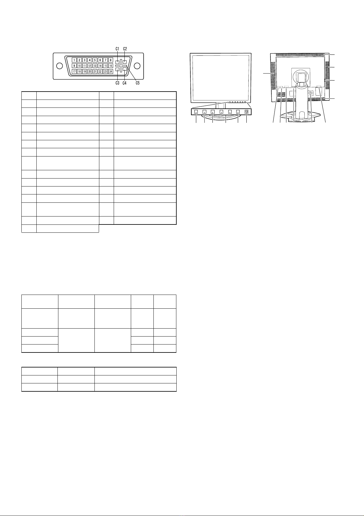
The DVI-I input connector pin
Power management
The monitor is based on the VESA DPMS*1and the DVI DMPM*2stan-
dards.
To activate the monitor's Power Management function, both the video
card and the computer must conform to the VESA DPMS standard and
the DVI DMPM standard.
*1 DPMS: Display Power Management Signalling
*2 DMPM: Digital Monitor Power Management
DDC (Plug & Play)
This monitor supports the VESA DDC (Display Data Channel) standard.
DDC is a signal standard for carrying out Plug & Play functions on the
monitor or PC. It transfers information such as degree of resolution
between the monitor and PC. You can use this function if your PC is
DDC compliant and if it is set so that it can detect the Plug & Play mon-
itor.
There are many varieties of DDC due to the differences between sys-
tems. This monitor works with DDC2B.
PRODUCT DESCRIPTION
No. Function No. Function
1 TMDS data 2- 16 Hot plug detection
2 TMDS data 2+ 17 TMDS data 0-
3 TMDS data 2/4 shield 18 TMDS data 0+
4 N.C. 19 TMDS data 0/5 shield
5 N.C. 20 N.C.
6 DDC clock 21 N.C.
7 DDC data 22 TMDS clock shield
8 Analogue vertically
synchronised signal 23 TMDS clock +
9 TMDS data 1- 24 TMDS clock -
10 TMDS data 1+ C1 Analogue red image signal
11 TMDS data 1/3 shield C2
Analogue green image signal
12 N.C. C3
Analogue blue image signal
13 N.C. C4 Analogue horizontally
synchronised signal
14 +5V C5 Analogue GND
15 GND
DPMS mode Screen Power
consumption H-sync V-sync
ON Display on 51W
(withnoaudio
input)
Yes Yes
STANDBY Display off 5W No Yes
SUSPEND Yes No
OFF No No
DPMS mode Screen Power consumption
ON Display on 51W (with no audio input)
OFF Display off 5W
1. INPUT button: To switch between the signals input termi-
nals. (Input terminal 1 0Input terminal 2)
2. MENU button: This button is used to pop-up, select and
close the OSD (On Screen Display) Menu.
3. cbutton: This button is used to select menu options
when the OSD Menu is displayed.
4. e d buttons: When the OSD Menu is displayed:
These buttons are used to increase or
decrease the value of a selected option.
When the OSD Menu is not displayed:
These buttons are used to adjust backlight
brightness and speaker volume.
5. Power button
6.PowerLED: This LED is lit green when in use and
orange when in power-saving mode.
7. Speakers: Audio entering via the monitor and the
external device connected to the monitor
can be heard.
8. Headphone terminal: Headphones (commercially available) can
be connected here.
9. Audio input terminal: A computer’s audio output terminal can be
connected here. The audio cable included
should be used.
10. DVI-I input terminal:
(INPUT-2) The computer’s digital RGB output terminal
or analog RGB output terminal can be con-
nected here.
Separately sold cables are necessary for
connection.
For a digital signal input: It can be con-
nected to a computer with a DVI-compatible
output terminal (DVI-D24 pin or DVI-I29 pin)
and which has SXGA output ability.
Depending on the computer to be con-
nected, correct display may or may not be
possible.
11. Analog RGB input
terminal(INPUT-1) The analog signal cable is connected
here.The analog signal cable included
should be used.
12. Security lock anchor: By connecting a security lock (commercially
available) to the security lock anchor, the
monitor is fixed so that it cannot be trans-
ported.
The security slot works in conjunction with
Kensington Micro Saver Security Systems.
13. Power terminal
14. Main power switch
15. Ventilation openings:
Note: Never block the ventilation openings
as this may lead to overheating inside the
monitor and result in malfunction.
12 3 4 5 6
Rear side
810 13
14
12
7
9
Front side
11
15
15
7