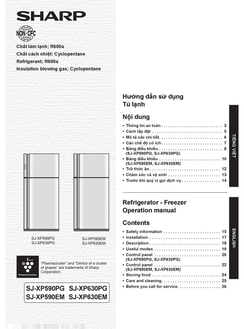
Sharp SJ-GF60X-T User manual

SERVICE MANUAL
This document has been published to be used for
after sales service only.
The contents are subject to change without notice.
Refrigerator-freezer
MODEL
SJ-GF60X-T
No.S0310SJF60XTFT
DESTINATION F
CONTENTS
Refer to "REFRIGERATING-CYCLE REPAIR MANUAL" for handling this refrigerant.
Refrigerant; R600a
[1] PRODUCT SPECIFICATIONS
1. SPECIFICATIONS ………………………… 2
2. ACCESSORIES …………………………… 2
3. AUTOMATIC ICE MAKING ……………… 3
[2] DESIGNATION OF VARIOUS PARTS
1. PART NAMES ……………………………… 4
2. INTERNAL STRUCTURE ………………… 5
3. FLOW OF COOL AIR ……………………… 6
4. TEMPERATURE DISTRIBUTION………… 7
[3] DIMENSIONS
1.
OUTER DIMENSIONS AND CLEARANCE
…8
2. INNER DIMENSIONS ……………………… 9
[4] ELECTRICAL CIRCUIT DIAGRAMS…………10
1. WIRING DIAGRAM …………………………10
2. ELECTRIC ACCESSORIES LAYOUT …… 11
3.
PRECAUTIONS FOR USING LEAD-FREE SOLDER
……12
[5] ELECTRICAL SYSTEM SPECIFICATIONS…13
1. FUNCTIONAL PART SPECIFICATIONS…13
2. MODE FOR DISPLAY………………………14
[6]
REFRIGERATION CYCLE SYSTEM SPECIFICATIONS
1. R600A PRECAUTIONS ……………………15
2.
TABLE OF R600A CHARACTERISTICS
…15
3. REFRIGERATION CYCLE DIAGRAM……15
4.
REPAIR OF THE REFRIGERATION CYCLE
…17
[7] TROUBLESHOOTING
1. SELF-DIAGNOSIS MODE …………………18
2.
FORCED STOPPING OF DOOR ALARM BUZZER
…22
3.
THERMISTOR CIRCUIT CHECK METHOD
…22
4.
INSPECTION FLOWCHART AND REPAIR ITEMS
…23
5.
PLASMACLUSTER OK/NG JUDGMENT
…25
[8] DISASSEMBLY/ASSEMBLY
1.
GENERAL DISASSEMBLY SEQUENCE
…26
2.
REFRIGERATOR COMPARTMENT DISASSEMBLY
…27
3. FREEZER COMPARTMENT/ICE
COMPARTMENT DISASSEMBLY ………29
4. HOW TO REMOVE OP. PWB ASS'Y ……31
5. HOW TO REMOVE TERMINAL BOX ……31
6. HOW TO INSTALL R-SUB PACKING ……32
7.
HOW TO INSTALL DUCT RT ASS'Y COVER
…33
8.
ADJUSTMENT OF R-DOOR (DOUBLE DOOR)
…34
9. MAIN PARTS ASSEMBLY…………………35
Parts Guide
SJGF60XT
2
[1] PRODUCT SPECIFICATIONS
SPECIFICATIONS1.
Item SJ-GF60X-T
Rated voltage/Rated frequency 110V ~60Hz
Rated input (W) 127
Rated power input of heating systems (W) 189
Defrosting input (W) 155
Defrosting heater input (W) 155
O u t e r d i m e n s i o n s
Width×Depth×Height (mm) 750 x 728 x 1820
Rated total storage volume 601L (21.2 cu.ft.)
Refrigerator compartment 315L (11.13 cu.ft.)
Freezer compartment (upper) 37L (1.31 cu.ft.)
Freezer compartment (lower) 120L (4.24 cu.ft.)
Ice compartment 19L (0.67 cu.ft.)
Vegetable compartment 110L (3.89 cu.ft.)
Weight (kg) 106
Refrigerant (Charging quantity) [Flammable] R600a (72g)
Insulation blowing gas [Flammable] Cyclo pentane (HC)
Cabinet
Inner box material ABS plastic
Outer shell material PET steel
(Hot dipped zinc plated steel sheet with baked polyester resin coating)
Door Door shell material Glass
Door inner material ABS plastic
Temperature control Automatic(adjustable)
Defrosting system Heater system
(automatic start, automatic finish)
Refrigerator lamp LED (8 pcs)
Adjustable legs 2
Casters 4
Climate class ST
PLUG TYPE
Plug cord 2pin
Plug type A-1
Destination mark F
COLOR
Items -T
Outside color Brown
Inside color White
ACCESSORIES2.
Refrigerator Compartment
R shelf 2
Free set shelf (left) (front/back) 1 each
Free set shelf (right) (front/back) 1 each
Chilled case 1
Chilled case tray 1
Case 1
Door pocket (left) 2
Door pocket (right) 2
Egg case 1
Egg tray 1
Bottle pocket (left/right) 1each
Water tank (Tank cap, Lock lever, Slide cap,
Filter case, Water tank, Water filter) 1

SJGF60XT
3
Freezer compartment (Upper)
Freezer case (Upper) 1
Stainless tray 1
Freezer compartment (Lower)
Freezer case (top) 1
Freezer case (bottom) 1
Ice compartment
Ice storage box 1
Noise-proof sheet 1
Ice scoop 1
Vegetable compartment
Vegetable case 1
Fruit case 1
Pet case 1
Stainless tray 1
Other Accessories and Printed Materials
Foot grille 1
Operation manual 1
Warranty card 1
Control label 1
AUTOMATIC ICE MAKING3.
Water supply method: Storing water in tank/Direct water supply to ice cube maker•
Water tank volume: Approx. 1.2 L•
Ice making capacity (External air temperature: 30ºC, No door opening/closing, Temperature control: “• 中”, Ice-making mode: “ 通常 ”)
Ice cube size Standard Large
Daily Approx. 1.2 kg Approx. 1.5 kg
Once (8 pieces) Approx. 100 g Approx. 230 g
Ice-making time/once•
Ice cube size Standard Large
Ice making
mode
通常 Approx. 2 hours Approx. 3 hours and 30 minutes
キラット Approx. 6 hours Approx. 8 hours
おいそぎ Approx. 1 hour and 20 minutes Approx. 2 hours
Others: Water filter is attached.•
Ice scoop is provided.
Enables test operation with the cleaning function.
Heat-resistant temperature of water tank: Approx. 60ºC•
Ice storage quantity•
Ice cube size Standard Large
Normal Approx. 48 to 64 pcs. Approx. 24 to 32 pcs.
Maximum (when leveled) Approx. 96 to 112 pcs. Approx. 40 to 48 pcs.

SJGF60XT
4
[2] DESIGNATION OF VARIOUS PARTS
PART NAMES1.
Parts names in parentheses "[ ]" are denominations used in the Operation manual.
ྑ
>@
Ice compartment Freezer compartment (upper)
Freezer compartment (lower)
Noise-proof sheet
Ice storage box
Ice scoop F case sus
F case s
F top case
F bottom case Vegetable case
Fruit case
V case sus
Pet case
Vegetable compartment
Free set shelf(left)
Egg case
Egg tray
Water tank
Bottle pocket(left) Bottle pocket(right)
Cool plate
Door pocket(left) Door pocket(right)
Case
Chilled case
C case tray
LED [ ]
[ ]
[ ]
[ ]
[ ]
[ ]
[ ]
[ ]
[ ]
[ ]
[ ]
[ ] [ ]
[ ]
[ ]
[ ]
[ ]
[ ]
[ ]
[ ]
[ ]
[ ]
[ ]
[ ] Free set shelf(right)
Plasmacluster unit
R shelf
[ ]

SJGF60XT
5
INTERNAL STRUCTURE2.
Catalyzer
Humidity sensor
Fan motor
Proximity switch
Thermo fuse
Fan motor
Catalyzer
Ice compartment Freezer compartment (upper)
Freezer
compartment (lower)
Vegetable compartment
Refrigerator compartment
R-shower duct ass’y
D-fan motor PCI
Damper ass’y
V heater
Thermistor
Ice cube heater
Evaporator
Terminal box
(Main PWB, EECON-INV PWB, REACTANCE)
Compressor, protector, valve turret
Fan motor g
Condenser unit
Caster
Evaporating pan
Side view
Adjustable leg ass’y
F proximity switch
Ice maker ass’y
OP.PWB
Transparant electrode
R door switch
LED PWB ass’y
Cool plate
LED PWB ass’y
R-thermistor
Gear pump
Water pipe ass’y
Water pipe heater
Tank heater
F-thermistor
Evaporator
Heater
Front view
Fan motor f
DEF thermistor

SJGF60XT
6
FLOW OF COOL AIR3.
Ice compartment
Freezer compartment (upper)
Freezer
compartment (lower)
Refrigerator compartment
Freezer
compartment (lower)
Vegetable compartment
Side view
Front view
Refrigerator compartment
Ice compartment Freezer compartment (upper)
Vegetable compartment
Flow of Cool air
When Plasmacluster ion is in operation.

SJGF60XT
7
TEMPERATURE DISTRIBUTION4.
●
The temperatures above are indications under the condition of no
food inside, doors closed and surrounding temperature is 30 after
stabilized the inside temperature. (Temperature adjustment is "中")
Approx.3 7°C Approx.2 5°C Approx.3 7°C
Approx.0 2°C
Approx.-17 -19°C
Approx.-18 -20°C
Approx.-18 -20°C
Approx.3 8°C

SJGF60XT
8
[3] DIMENSIONS
OUTER DIMENSIONS AND CLEARANCE (UNIT:mm)1.
174 230
728
285 461
616
697.5
691.5
641
68
691.5
4
750
1820
853.2180.8335
365 8
8
15.5
50
732.5
125 118
Moving wheels
back side
Moving wheels
front side
Adjustable feet
More than
960
1136
728
60 60
More than More than
60
More than
60
More than
90
mm

SJGF60XT
9
INNER DIMENSIONS2.
The dimensions between shelves can be changed by setting the shelves on the other rails.•
348
319
348
619
353
357
215
208
208
584
593
366 208
172
118
67
95
96
96
246
226
392
81.5
70
70
417.8
424
420
280
50
112
203
412
589
589
135 334
334
309
334
142
142
144
75
75
75
144
75
122
123
123
123
135
94
163
417.8
105
66
100 71
348
311911
319
348
50
424 597
282
310
63
353
88
105
404
110.5
138.5
95.5
89
440
119 113 125
140

SJGF60XT
10
[4] ELECTRICAL CIRCUIT DIAGRAMS
WIRING DIAGRAM1.
Source cord
Reactance
Main PWB
OP
PWB
EECON-INV
PWB
Protector Compressor
Fan
motor g
Fan
motor f
R-fan
motor
LED
PWB
(left)
Indicator
PWB
Plasmacluster
unit
Motor
D-fan motor PCI
Gear
pump
Damper
R
thermistor
F thermistor
DEF thermistor
Ice maker unit
Motor
Switch
Thermistor
Proximity
switch
F proximity
switch
Ice cube
heater
Water
pipe
heater
R door
heater
V heater
Door
switch
(left)
Door
switch
(right)
LED
PWB
(right)
Terminal box
Valve turret
Humidity sensor
Heater
Thermo fuse
Tank heater

SJGF60XT
11
ELECTRIC ACCESSORIES LAYOUT2.
Black
Blue
Brown
Compressor
Compressor ass’y
Comp. harness
Red
Inverter DC harness
EECON-INV PWB
White
Green
Earth harness
MAIN PWB
Terminal box
Indicator
PWB
Red
Gray
Orange
White
Yellow
Black
Motor
Brown
Brown
Black
White
White
White
Brown
Brown
White
White
Red
Black
Red Purple
Gray
Black
Purple
Gray
Red
Red
Orange
Orange
Orange
Orange
Yellow
Yellow
Blue
Light green
Light green
Light green
Damper harness
Gray
Blue
Reactance
G-fan
Reactance
Fan motor
F thermistor
DEF thermistor
Heater
F-proximity switch
V-heater
Humidity sensorR door heaterOP.PWB
Valve turret
Tank heater
Harness
Harness
Harness
Harness
Black
Black
Black
White Heater
Thermo fuse
Blue
Red
Red
Orange
Yellow
Light green
White
White
White
White
Blue
Blue
Black
Black
Brown
Yellow
Black Brown
F proximity
switch
Gray
Brown
Brown
Red
Harness
OP PWB
R door
heater
Humidity
sensor
LED PWB
(left)
Ice cube tray
Ice cube heater
Light
green Blue
Brown
Light
green
Thermistor
Ice maker unit
Harness
R-damper
R fan motor
Gear pump
Water pipe
R thermistor
R door switch
(left)
R door
switch(right)
Water pipe
heater
SW
Motor
LED PWB
(right)
Ice cube heater
Gear
pump
R
damper
Water pipe heater
Source cord
Black
White
WhiteWhiteYellowBrown
V-heater
harness
Valve turret
Valve turret
Green
/Yellow
Green
/Yellow
Protector
Black
Yellow
Proximity switch
Moter
Tank heater
Proximity
switch
Black
Brown
Blue
Black
Red
Gray
Red
Red
Blue Orange
Light green
Yellow
Yellow
White
White
White
White
White
Light green
Black
White
Gray
White
White
Gray
Brown
Brown Brown Brown
Blue Blue
Gray
Red
Red Red Red
Orange
Yellow
Orange
Orange
Orange
Yellow
Yellow Yellow
Blue
Red
Brown
Red
Red
Red
Brown
Brown
Brown
Brown
Brown
Brown
Brown
Brown
Brown
Brown
Brown
Red
Brown
Brown
White
White
White
White
White
White
White
Orange
Orange
Orange
Orange
Orange
Orange
Orange
Orange
Purple
Purple
Orange
Light green
Light green
Light green
Light green
Light green
Light green
Light green
Light green
Red
Red
Red
Red
Red
Red
Red
Red
Orange
Yellow
Yellow
Yellow
Yellow
Yellow
Yellow
Yellow
Yellow
Yellow
Light green
Blue
Blue
Blue
Blue
Gray
Blue
Blue
Black
Black
Black
Black
Black
Gray
Gray
Gray
Gray
Gray
Gray
Yellow
Orange
White
Motor
Indicator PWB
LED PWB(right)
LED PWB(left)
R door switch(left)
R door switch(right)
Green
Blue
Brown

SJGF60XT
12
PRECAUTIONS FOR USING LEAD-FREE SOLDER3.
1) Employing lead-free solder
The PWB of this model employs lead-free solder. This is indicated by the "LF" symbol printed on the PWB and in the
service manual. The suffix letter indicates the alloy type of the solder.
Example:
Indicates lead-free solder of tin, silver and copper
2) Using lead-free wire solder
When repairing a PWB with the "LF" symbol, only lead-free solder should be used. (Using normal tin/lead alloy
solder may result in cold soldered joints and damage to printed patterns.)
As the melting point of lead-free solder is approximately 40°C higher than tin/lead alloy solder, it is recommend that a
dedicated bit is used, and that the iron temperature is adjusted accordingly.
3) Soldering
As the melting point of lead-free solder (Sn-Ag-Cu) is higher and has poorer wettability, (flow), to prevent damage
to the land of the PWB, extreme care should be taken not to leave the bit in contact with the PWB for an extended
period of time. Remove the bit as soon as a good flow is achieved.The high content of tin in lead free solder will
cause premature corrosion of the bit. To reduce wear on the bit, reduce the temperature or turn off the iron when it is
not required.
Leaving different types of solder on the bit will cause contamination of the different alloys, which will alter their
characteristics, making good soldering more difficult. It will be necessary to clean and replace bits more often when
using lead-free solder. To reduce bit wear, care should be taken to clean the bit thoroughly after each use.

SJGF60XT
13
[5] ELECTRICAL SYSTEM SPECIFICATIONS
FUNCTIONAL PART SPECIFICATIONS1. Part Name Specifications Function
Fan motor F
(F fam motor)
Model No.: 4715JL-09W-S37-GF8
Rating: DC15V
Power Input: 1.05W (Vs:2.6V)
For cooling
(For freezer compartment)
Fan motor
(R fam motor)
Model No.: D08A-12PM
Rating: DC12V
Power Input: 0.84W
For cold air circulation
(For refrigerator compartment)
Fan motor g
(condenser fan motor)
Model No.: 4515JL-09W-S10-G01
Rating: DC15V
Power Input: 1.2W
For condensing
(Out side refrigerator)
D-fan motor PCI
Model No.: D09F-12SM20(EX)
Rating: DC12V 0.13A
Power Input: 1.56W
For ion releasing
(For refrigerator compartment)
Damper ass'y (R damper) 415 ± 5Ω(25°C) For refrigerator compartment temperature control
Motor Rating: DC12V 0.13A 300ΩDeodorant/bacteria elimination switching damper
Door switch
(R door switch) 5mA 5V DC For detection of opening or closing of the door
(For refrigerator compartment)
Proximity switch
(I door switch) DC15V 100mA 1W For detection of opening or closing of the door
(For Ice compartment)
F proximity switch
(Freezer (bottom) door switch) DC15V 100mA 1W For detection of opening or closing of the door
(For freezer compartment (bottom))
Compressor
Model No.: VESD9C+
Rating: 100V 50/60Hz
Resistance value: 9.6Ω(at 25°C)
Protector MODEL: MSP59AMN-6
Operating temperature: 120°C For compressor overload prevention
Main PWB For main control
OP.PWB For operation panel control (touch panel)
LED PWB 15V 72mA 1.125W For refrigerator compartment illumination
Indicator PWB 3.2V 20mA 64mW
Source cord 125V 7A Source cord (2 Pin + earth)
F thermistor Resistance: 6.4kΩ(at 0°C) For detection of the freezer compartment temperature
R thermistor Resistance: 6.4kΩ(at 0°C) For detection of the refrigerator compartment temperature
DEF thermistor Resistance: 15kΩ(at 0°C) Senses when defrosting is completed
Thermo fuse Rating: 250 V 10 A
Rated operating temperature: 77°C For defrosting temperature excessive rise prevention
Thermistor Resistance value: 6.0kΩ(at 0°C) For detection of ice tray temperature
Gear pump Supplies water to the ice cube maker
Heater 110V 155W 78ΩFor defrosting
Plasmacluter unit DC15V 34mA For bacteria elimination in compartment
Reactance 11mH±10% Class E wiring
EECON-INV PWB 100V 50/60Hz For compressor drive
Ice cube heater 12W 833ΩFor making clear ice cube
Humidity sensor 0.5mA 5V DC For detection of outside temperature and humidity
Valve turret For switching refrigerant
Partition heater(R door heater) 3.4W/2910ΩFor refrigerator compartment door condensation prevention
Water pipe heater 2.8W/3565ΩFor water pipe freezing prevention
Tank heater 1.0W/9638ΩAvoid the water tank from freezing
V heater ass'y 9.0W/1110ΩFor vegetable compartment temperature compensation
:Unexchengeable parts or Independently unexchangeable parts.

SJGF60XT
14
MODE FOR DISPLAY2. How to set the product in this mode2-1.
Open the doors of the refrigerator compartment and the ice compartment within 2 minutes after turning ON the•
power to the main unit, and press and hold the [ 戻る ] button for 5 seconds or longer.
How to cancel this mode2-2.
With the doors of the refrigerator compartment and the ice compartment opened, press and hold the [• 戻る ] button
for 5 seconds or longer.
Even if the main power supply is turned OFF, the display mode will be maintained. (not be cancelled)
Operation in the display mode2-3.
Each load (compressor, each fan motor, all heaters, damper, ice release motor, water pump motor) stops.1)
The damper is normally kept opened.2)
Even if the ice compartment or the refrigerator compartment (lower) door is opened, the door-open buzzer does3)
not sound.
When the refrigerator compartment door is opened:4)
The refrigerator compartment illumination lamp and indicator LED are lit.•
The cooling/refrigerator compartment PCI fan motor operates.•
The door-open buzzer does not sound.•
Operation panel5)
<Outside of compartment>
The operation panel lamps on the door will blink in sequence one by one.•

SJGF60XT
15
[6] REFRIGERATION CYCLE SYSTEM SPECIFICATIONS
R600A PRECAUTIONS1.
•Do not use any refrigerant other than R600a.
•Gas leak testers for HFC-134a, CFC-12, HCFC-22, etc., cannot be used.
•A special tool is used for the R600a cycle.
TABLE OF R600A CHARACTERISTICS2.
Refrigerant saturated vapor pressure table R600a
(Unit) Temperature: °C, Pressure: kgf/cm abs
Temperature
Pressure
-20 -15 -10 -5 0 10 15 20 25 30 35 40 45 505
0.74 1.601.340.91 1.11 1.91 2.25 2.64 3.08 3.58 4.13 4.74 5.42 7.006.17
(Unit)Temperature:°C, Pressure: MPa abs
Temperature
Pressure
-20 -15 -10 -5 0 10 15 20 25 30 35 40 45 505
0.073 0.1570.1310.089 0.109 0.187 0.221 0.259 0.302 0.351 0.405 0.465 0.532 0.6860.605
REFRIGERATION CYCLE DIAGRAM3. Piping Diagram3-1.
Evaporator
Charge pipe
Compressor
Discharge pipe
kit
Capillary
tube B
Dryer
Capillary
tube A
Charge pipe
①
②
③⑤
⑦
⑨
⑬
⑮
⑪
⑧
④
⑯
⑫
⑥
⑩
⑭
⑰
⑳
⑲
⑱
Dew proofing condenser
Extra
cond.
unit kit
←(①~⑳)
Show the order ofthe refrigerant flow
Bottom
condenser
Back
condenser
Suction
connector
Suction
pipe
Valve
turret
Extension
barrel
Side
condenser L
Side
condenser R

SJGF60XT
16
Schematic diagram3-2.
Suction connector
Compressor
Value turret kit
Suction pipe
Charge pipe
(Low presure side)
Capillary tube A
I. D.0.55
Side condenser L
Side
condenser R
Discharge pipe kit
Dryer Back condenser
Bottom condenser
Evaporator
Charge pipe
(High presure side)
Extra cond. unit kit
Extra cond.
unit
D.P
condenser
Capillary tube B
I. D.0.7
Piping detail drawing3-3.
:
Side condenser R Outlet
Dew proofing condenser
Inlet Side condenser R
Inlet Suction pipe
Charge pipe Discharge pipe
ass’y
Evaporating pan
Suction connector
Suction connector ass’y
Side condenser L
Outlet
Compressor
Charge pipe
R-valve ass’y
Dryer
Side condenser L
Inlet
Extra cond.unit
ass’y
Pinch point
Back condenser ass’y Outlet
Back condenser Inlet
Capillary tube B
Capillary tube A

SJGF60XT
17
Specifications of Refrigerant Valve Operation3-4.
Modes and operating conditions of refrigerant valve (3-way valve)1)
Valve is fully closed:1.
• This mode is used in compressor OFF status.
Only fine capillary is opened:2.
• During normal cooling operation
Only wide capillary is opened:3.
• During cooling operation under large load
Both capillaries are opened4.
• The refrigerator is set in this mode for only one minute after the power supply is turned ON. This mode is used for
vacuuming. During cooling operation, this mode is not used.
• Differentiation between fine capillary and wide capillary
- Fine capillary: Capillary tube A
- Wide capillary: Capillary tube B
- The fine capillary is identified with a yellow mark.
Fault and status of refrigerant valve2)
• There is no method to give an instruction from the PWB and confirm the valve position.
Refrigerant valve status Problem
1Both capillaries are opened, and the valve does not operate.
No problem on cooling operation No problem
2Only the fine capillary is opened, and the valve does not operate.
Cooling performance deteriorates under large load.
Refrigerant shortage may occur, causing frost around
the evaporator inlet to increase.
3Only the wide capillary is opened, and the valve does not operate.
No problem on cooling operation No problem
4Both capillaries are closed, and the valve does not operate.
Cooling operation is disabled.
Cooling operation is disabled even when the
compressor is ON.
• Fault of the refrigerant valve cannot be displayed in the self-diagnosis mode.

SJGF60XT
18
[7] TROUBLESHOOTING
SELF-DIAGNOSIS MODE1. Outline1-1.
The self-diagnosis mode stores fault data for 5 days in the past (including “today”), and displays them by the date•
in the order of occurrence.
Self-diagnosis data to be displayed Storage of self-diagnosis result
Current fault Fault history
All faults that have currently occurred
(Displayed in the order of fault number)
Faults that occurred in the past five days
(Displayed by the date in the order of occurrence)
Storage of fault data for the past five days
(Up to 9 items per day)
Self-diagnosis display•
Mode input “Current”
fault display “Today” fault
history display
“1-day before”
fault history display “2-days before”
fault history display “3-days before”
fault history display “4-days before”
fault history display
Button
operation Button
operation Button
operation Button
operation Button
operation
Display priority is given to the upper stages
of self-diagnosis display (Table 1) (All items) The last fault on that day is displayed first, and the older ones
are displayed in the order of occurrence. (Up to 9 items per day)
(Note 1) Self-diagnosis result data for 5 days (including “today”) are stored. 24 hours from the time when the
refrigerator power supply turned ON is defined as “one day”.
24 hours 24 hours 24 hours 24 hours 24 hours 24 hours
Today
Current time
1-day before 2-days before
Stored data
3-days before 4-days before n-days before
Refrigerator power supply
is turned ON
(Note 2) How to clear stored data
After turning ON the power to the main unit, open the doors of the refrigerator compartment and the ice1)
compartment within 2 minutes, and press and hold the [ 戻る ] button for 5 seconds or longer.
With the doors of the refrigerator compartment and the ice compartment opened, press and hold the [2) 戻る ]
button for 5 seconds or longer again.
Self-diagnosis mode1-2.
Mode input method1)
With the refrigerator compartment door opened (the temperature control1)
lamp unlit), press and hold the [ メニュー決定 ] button for 5 seconds.
(The buzzer sounds, “beep, beep”.)
The refrigerator enters the self-diagnosis mode.
* The self-diagnosis mode will be automatically canceled when the status
with no button operation continues for 3 minutes.
* If the refrigerator does not enter the self-diagnosis mode, a fault with the
door switch system can be considered.
クリーン
[メニュー決定] button

SJGF60XT
19
Operation in the self-diagnosis mode2)
The compressor is forcedly turned ON. (Excepting a period of defrosting operation and compressor ON delay•
time)
The cooling, condenser and R-fan motors are forcedly turned ON.•
(These motors will be forcedly turned ON even while the compressor is OFF. However, when the door is opened,
the motors other than the condenser fan motor are kept OFF.)
The refrigerator compartment/vegetable compartment PCI fan and the PCI are forcedly turned ON. (However,•
when the door is opened, the PCI and fan are kept OFF.)
When the refrigerator compartment door is opened, the R damper is forcedly closed. When the refrigerator•
compartment door is closed, the R damper is forcedly opened. (Opening/closing the refrigerator compartment
door activates the R damper operation.)
During execution of the self-diagnosis mode, and for 20 minutes after cancellation of this mode, self-diagnosis•
data serial output is executed.
During execution of the self-diagnosis mode, and for 20 minutes after cancellation of this mode, the door-open•
buzzer does not sound.
Operation during self-diagnosis mode, and self-diagnosis display3)
Self-diagnosis data is displayed on the temperature control panel. (Refer to self-diagnosis display [Table 1].)1)
Self-diagnosis display can be switched by operating the temperature control panel buttons.2)
Temperature control panel button Operation
[▼] Fault data forward scroll
[▲] Fault data reverse scroll
[メニュー決定 ] Fault occurrence date forward scroll
クリーン
Fault occurrence
date
(Forward scroll) Fault data
(Forward scroll)
Fault data
(Reverse scroll)

SJGF60XT
20
<Example of button operations and self-diagnosis display>
* During self-diagnosis mode input, the “current” fault is displayed.
・
・
・ ・
・
・
・
・
・
[During mode input]
“Current” fault
Display of the fault
at the top of Table 1
Press [▲].
Press [▼].
Press [▲].
Press [▼].
Display of the fault at
the second top of Table 1
Display of all faults
that have occurred
Press
[メニュー決定].
Press
[メニュー決定].
Press
[メニュー決定].
“Current” fault history
Press
[メニュー決定].
Press
[メニュー決定].
Press
[メニュー決定].
Display of the
latest fault
Display of the
second latest fault
Press [▲].
Press [▼].
Press [▲].
Press [▼].
Press [▲].
Press [▼].
Press [▲].
Press [▼].
Display of up to 9 items Display of up to 9 items
“1-day before”
fault history
“2-day before”
fault history
Display of the
last fault
Display of the fault just
before the last
“3-days before”
fault history
“4-days before”
fault history
* During forward/reverse scroll of fault display with [▼]/[
▼
] button, if fault data to be displayed next does not exist,
the buzzer sounds “beep-beep”, and the display will not change.
* To display a fault occurrence date for currently displayed data, press the [ 冷凍・温度] lamp.
Fault occurrence date [ 冷凍・温度] lamp.
Current Unlit OFF
Today Lit ON
1-day before Blink once. Repeat "2-sec. OFF"/"0.5-sec. ON/0.5-sec. OFF".
2-days before Blink twice. Repeat "2-sec. OFF"/"0.5-sec. ON/0.5-sec. OFF" twice.
3-days before Blink three times. Repeat "2-sec. OFF"/"0.5-sec. ON/0.5-sec. OFF" three times.
4-days before Blink four times. Repeat "2-sec. OFF"/"0.5-sec. ON/0.5-sec. OFF" four times.
Example of lamp indication: “2-days before”
0.5-sec. 0.5-sec. 0.5-sec. 0.5-sec. 0.5-sec. 0.5-sec. 0.5-sec. 0.5-sec.
2-sec. pause 2-sec. pause
Repeat
ON
OFF
Table of contents
Other Sharp Refrigerator manuals

Sharp
Sharp SJ-FP760V User manual

Sharp
Sharp SJ-GC680V User manual

Sharp
Sharp SJ-LE123M1X-EU User manual

Sharp
Sharp SJ-T2435H4I-EU User manual

Sharp
Sharp FD-450NF User manual

Sharp
Sharp SJ-BA35CHXI2-UA User manual

Sharp
Sharp SJ-P43N-SL1/WH1 User manual

Sharp
Sharp SJ-T1400M0W-EU User manual

Sharp
Sharp SJ-X345E User manual

Sharp
Sharp SJ-LF300E00X-EN User manual

Sharp
Sharp SJ-BA31IMXI2-EU User manual

Sharp
Sharp SJ-GC400V User manual

Sharp
Sharp SJ-FS79V User manual

Sharp
Sharp SJ-BB10DTXWE-EU User manual

Sharp
Sharp SJ-F624ST User manual

Sharp
Sharp SJ-BB05DTXLD-EU User manual

Sharp
Sharp SJ-T1227M5W-UA User manual

Sharp
Sharp SJ-25P User manual

Sharp
Sharp SJ-XP470HB User manual

Sharp
Sharp SJ-GC680V User manual