Sharp CD-MD3000H User manual

Thank you for purchasing this SHARP product.
To obtain the best performance from this product, please read this
manual carefully. It will guide you in operating your SHARPproduct.
CD-MD3000HAudio Tower System consisting of CD-MD3000H (main
unit) and CP-RW5000H (speaker system).
AUDIO TOWER SYSTEM
MODEL
CD-MD3000H
OPERATION MANUAL
If you require any advice or assistance re-
garding your Sharp product, please visit our
web-site www.sharp.co.uk/support.
Customers without internet access may tele-
phone 08705 274277 during office hours (or
(01) 676 0648 if telephoning from Ireland).

2Web-site: www.sharp.co.uk/support Help Line: 08705 274277 (office hours)
Important Instruction
Special Notes
NOTES FOR USERS IN THE U.K. AND IRELAND
The mains lead of this product is fitted with a non-rewireable (moulded) plug incorpo-
rating a 3A fuse. Should the fuse need to be replaced, a BSI or ASTA approved BS
1362 fuse marked or and of the same rating as above, which is also indicated on
the pin face of the plug must be used.
Always refit the fuse cover after replacing the fuse. Never use the plug without the
fuse cover fitted.
In the unlikely event of the socket outlet in your home not being compatible with the
plug supplied, cut-off the mains plug and fit an appropriate type.
DANGER:
The fuse from the cut-off plug should be removed and the cut-off plug destroyed
immediately and disposed of in a safe manner.
Under no circumstances should the cut-off plug be inserted elsewhere into a 13A
socket outlet as a serious electric shock may occur.
To fit an appropriate plug to the mains lead, follow the instructions below:
IMPORTANT:
The wires in the mains lead are coloured in accordance with the following code:
Blue : Neutral
Brown : Live
As the colours of the wires in the mains lead of this product may not correspond with
the coloured markings identifying the terminals in your plug, proceed as follows:
●The wire which is coloured blue must be connected to the plug terminal which is
marked N or coloured black.
●The wire which is coloured brown must be connected to the plug terminal which is
marked L or coloured red.
Ensure that neither the brown nor the blue wire is connected to the earth terminal in
your three pin plug.
Before replacing the plug cover, make sure that:
●If the new fitted plug contains a fuse, its value is the same as that removed from
the cut-off plug.
●The cord grip is clamped over the sheath of the mains lead and not simply over the
lead wires.
IF YOU HAVE ANY DOUBT, CONSULTAQUALIFIED ELECTRICIAN.
SERVICE INFORMATION
In the unlikely event of your equipment requiring repair, please contact the dealer or
supplier from whom it was purchased. Where this is not possible, please visit our
web-site www.sharp.co.uk/support.
Customers without internet access may telephone 08705 274277 during office hours
(or (01) 676 0648 if telephoning from Ireland).
Please note; all calls will be charged at local rate.
Certain replacement parts and accessories may be obtained from our main parts
distributor. WILLOW VALE ELECTRONICS LTD.
0121 766 5414
In the unlikely event of this equipment requiring repair during the guarantee period,
you will need to provide proof of the date of purchase to the repairing company.
Please keep your invoice or receipt, which is supplied at the time of purchase.
WARNINGS
●When the ON/STAND-BY button is set at STAND-BY position, mains voltage is still
present inside the unit.
WhentheON/STAND-BYbuttonissetatSTAND-BYposition,theunitmaybebrought
into operation by the timer mode or remote control.
●This unit contains no user serviceable parts. Never remove covers unless qualified
to do so. This unit contains dangerous voltages, always remove mains plug from the
socket before any service operation and when not in use for a long period.
●To prevent fire or shock hazard, do not expose this appliance to dripping or splash-
ing. No objects filled with liquids, such as vases, shall be placed on the apparatus.
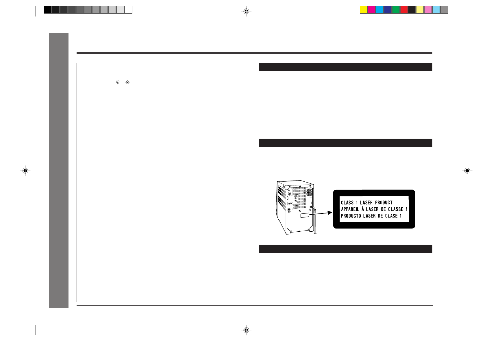
CAUTION
●Use of controls, adjustments or performance of procedures other than those speci-
fied herein may result in hazardous radiation exposure.
●As the laser beam used in this compact disc player is harmful to the eyes, do not
attempt to disassemble the cabinet. Refer servicing to qualified personnel only.
NOTES
●Recording and playback of any material may require consent, which SHARP is
unable to give. Please refer particularly to the provisions of the Copyright Act
1956, the Dramatic and Musical Performers ProtectionAct 1958, the Performers
ProtectionActs 1963 and 1972 and to any subsequent statutory enactments and
orders.
●This equipment complies with the requirements of Directives 89/336/EEC and 73/23/
EEC as amended by 93/68/EEC.
●US and foreign patents licensed from Dolby Laboratories.

3
Web-site: www.sharp.co.uk/support Help Line: 08705 274277 (office hours)
Important Instruction
Contents
■Important Instruction Page
Special Notes .......................................................................................2
■General Information
Precautions .......................................................................................4-5
Accessories .........................................................................................5
Controls and Indicators .................................................................6-11
■Preparation for Use
System Connections ....................................................................12-13
Remote Control .................................................................................14
■Basic Operation
General Control .................................................................................15
Sound Control ...................................................................................16
Setting the Clock ...............................................................................17
■CD Playback
Listening to a CD (CDs) ...............................................................18-19
■MD Playback
Listening to a MiniDisc ................................................................20-21
■Advanced CD/MD Playback
Programmed Play ..............................................................................22
Repeat or Random Play ....................................................................23
To Specify a Disc to Play (CD Only).................................................23
Switching the Time Display ..............................................................23
■Tape Playback
Listening to a Cassette Tape ............................................................24
■Radio
Listening to the Radio..................................................................25-26
■RDS Radio
Using the Radio Data System (RDS) ......................................... 27-34
■MD Recording Page
Before Recording to a MiniDisc .......................................................35
Recording to a MiniDisc from CDs ............................................ 36-38
Recording to a MiniDisc from a Cassette Tape ..............................39
Recording to a MiniDisc from the Radio .........................................39
Checking Displays ............................................................................40
■Tape Recording
Recording to a Cassette Tape from a CD ........................................41
Recording to a Cassette Tape from a MiniDisc ..............................42
Recording to a Cassette Tape from the Radio................................43
■MD Editing
Titling a MiniDisc ..........................................................................44-45
Editing a Recorded MiniDisc ...................................................... 46-48
■Advanced Features
Timer and Sleep Operation......................................................... 49-51
Enhancing Your Stereo System ................................................. 52-53
■References
What is a MiniDisc?...........................................................................54
MiniDisc System Limitations............................................................54
Error Messages .................................................................................55
Troubleshooting Chart .................................................................56-57
Maintenance.......................................................................................58
Specifications ...............................................................................58-59
TERMS OF GUARANTEE ................................................. Back cover

4Web-site: www.sharp.co.uk/support Help Line: 08705 274277 (office hours)
General Information
Precautions
■General
●Please ensure that the equipment is positioned in a well ventilated area
and that there is at least 10 cm (4") of free space along the sides and back.
There must also be a minimum of 20 cm (8") of free space on the top of the
unit.
10 cm (4")
10 cm (4") 20 cm (8")
10 cm (4")
●Use the unit on a firm, level surface free
from vibration.
●Keep the unit away from direct sunlight,
strong magnetic fields, excessive dust,
humidity and electronic/electrical equip-
ment (home computers, facsimiles, etc.)
which generates electrical noise.
●Do not place anything on top of the unit.
●Do not expose the unit to moisture, to temperatures higher than 60°C
(140°F) or to extreme low temperatures.
●If your system does not work properly, disconnect the AC power lead
from the wall socket. Plug the AC power lead back in, and then turn on
your system.
●In case of an electrical storm, unplug the
unit for safety.
●Hold the AC power plug by the head when re-
moving it from the wall socket, as pulling the
lead can damage internal wires.
●Do not remove the outer cover, as this may
result in electric shock. Refer internal ser-
vice to your local SHARP service facility.
●The ventilation should not be impeded by cov-
ering the ventilation openings with items, such
as newspapers, tablecloths, curtains, etc.
●No naked flame sources, such as lighted candles, should be placed on the
apparatus.
●Attentionshould be drawntothe environmental aspectsof battery disposal.
●The apparatus is designed for use in moderate climate.
●This unit should only be used within the range of 5°C - 35°C (41°F - 95°F).
Warning:
The voltage used must be the same as that specified on this unit.
Using this product with a higher voltage other than that which is specified is
dangerous and may result in a fire or other type of accident causing damage.
SHARP will not be held responsible for any damage resulting from use of this
unit with a voltage other than that which is specified.
■Volume control
The sound level at a given volume setting depends on speaker efficiency,
location, and various other factors.
It is advisable to avoid exposure to high volume levels, which occur whilst
turning the unit on with the volume control setting up high, or whilst continu-
ally listening at high volumes.

5
Web-site: www.sharp.co.uk/support Help Line: 08705 274277 (office hours)
General Information
,,
,,,
,,,
,,
,,,
,,,
Speaker wire for
MAIN terminals × 2
AM loop aerial × 1
Remote control × 1
Speaker wire for
SUBWOOFER terminals × 2
Blue
Black Black
Red
Precautions (continued)
■Care of compact discs
Compact discs are fairly resistant to damage, however mistracking can oc-
cur due to an accumulation of dirt on the disc surface.
Follow the guidelines below for maximum enjoyment from your CD collection
and player.
●Do not write on either side of the disc, particularly the non-label side from
which signals are read.
Do not mark this surface.
●Keep your discs away from direct sunlight, heat, and excessive moisture.
●Always hold the CDs by the edges. Fingerprints, dirt, or water on the CDs
can cause noise or mistracking. If a CD is dirty or does not play properly,
clean it with a soft, dry cloth, wiping straight out from the centre, along the
radius.
■Cassette tape
●
For playback, use normal or low-noise tape for the
best sound. (Metal or CrO
2
tape is not recommended.)
For recording, use only normal tape.
●Do not use C-120 tapes or poor-quality tapes, as they
may cause malfunctions.
●Before loading a tape into the cassette compartment,
tighten the slack with a pen or pencil.
Cassettes have removable tabs which prevent accidental
recording or erasing.
Removing the tab will protect the corresponding side.
Cover the tab holes with adhesive tape to erase or record
again. Side A (1)
Tab for sideA (1)
Tab for side B (2)
Accessories
Note:
Only the above accessories are included.
Please confirm that the following accessories are included.
FM aerial × 1
“AA” size battery
(UM/SUM-3, R6, HP-7 or similar) × 2

6Web-site: www.sharp.co.uk/support Help Line: 08705 274277 (office hours)
General Information
Controls and Indicators
1
2
3
4
5
6
7
8
11
9
10
■Front panel Reference page
01. Cassette Compartment....................................................... 24, 41-43
02. Volume Up/Demo Button ....................................................15, 16, 50
03. Volume Down Button ..........................................................16, 50, 57
04. Timer Set Indicator..........................................................................50
05. On/Stand-by Button ............................................................15, 49, 57
06. CD Direct Play Buttons (with Indicator)/
CD Eject Buttons.................................................................18, 23, 41
07. Disc Trays ........................................................................................18
08. Headphone Socket..........................................................................52
09. MD Eject Button ..............................................................................21
10. MD Compartment ......................................................................20, 36
11. Control Panel Open/Close Button .................................................15

7
Web-site: www.sharp.co.uk/support Help Line: 08705 274277 (office hours)
General Information
■Control panel Reference page
12. CD/MD Play Mode Select Button ...................................................23
13. Equalizer Mode Select Button........................................................16
14. Extra Bass Button ...........................................................................16
15. Name/Toc Edit Button ................................................................44-48
16. Delete Button...................................................................................45
17. Menu Button ........................................................................17, 49, 51
18. Display/Character Button .........................................................40, 44
19. Jog Dial ................................................................................17, 26, 36
20. Enter Button ........................................................................17, 26, 36
21. Tuner (Band) Button .......................................................................25
22. MD Track Edit Button ......................................................................38
23. CD Button ............................................................................18, 36, 41
24. MD Button ..................................................................................20, 42
25. CD MD One Touch Edit Button..............................................37, 38
26. MD Auto Mark Select Button ....................................................39, 53
27. CD/MD Fast Reverse, Tape Fast Wind or
Tuning Down Button (with Indicator) ..........................19, 21, 24, 25
28. Stop Button (with Indicator)...............................................19, 21, 24
29. Tape Reverse Play Button (with Indicator) ....................... 24, 41-43
30. Tape Button ...............................................................................24, 43
31. Auxiliary Button ........................................................................50, 53
32. MD Record Button.....................................................................39, 53
33. MD Record Mode Button ....................................................36, 38, 53
34. MD Record Speed Select Button ...................................................37
35. Tape Record Pause Button ................................................ 41-43, 53
36. CD/MD Fast Forward, Tape Fast Wind or
Tuning Up Button (with Indicator) ...............................19, 21, 24, 25
37. CD/MD Play or Pause, Tape Forward Play Button
(with Indicator) ....................................................................19, 20, 24
Controls and Indicators (continued)
30
31
32
33
34
35
36
37
21
22
23
24
25
26
27
28
29
12 13 14 17
15
16
18
19
20

8Web-site: www.sharp.co.uk/support Help Line: 08705 274277 (office hours)
General Information
■Multi-function LCD display
01. CD Indicators
02. Function Indicator
03. Extra Bass Indicator
04. Timer Play Indicator
05. Sleep Indicator
06. Timer Recording Indicator
07. CD/MD Play Indicator
08. CD/MD Repeat Indicator
09. CD/MD Pause Indicator
10. FM Stereo Indicator
11. Tape Reverse Mode Indicator
12. FM Stereo Mode Indicator
13. Cassette Indicator
14. Level Meter
15. MD Indicator
16. Digital Source Indicator
17. Monaural Long-Play Mode Indicator
18. Disc Name Indicator
19. Auto Mark Indicator
20. Memory Indicator
21. Total Indicator
22. Track Name Indicator
23. Track Edit Indicator
24. Random Play Indicator
25. CD All Disc Play Indicator
26. Remain Indicator
27. Record Indicator
28. RDS Indicator
29. Radio Text Indicator
30. Clock Time Indicator
31. Dynamic PTY Indicator
32. Traffic Programme Indicator
33. TOC Indicator
34. Synchronised Recording Indicator
35. EON Indicator
36. Traffic Information Indicator
37. Programme Type Indicator
38. Traffic Announcement Indicator
Controls and Indicators (continued)
1
2
3
4
5
6
7
8
9
10
11
12
18
19
20
21
22
23
24
25
26
27
28
29
30
31
32
33
34
35
36
37
38
13 14 15 16 17

9
Web-site: www.sharp.co.uk/support Help Line: 08705 274277 (office hours)
General Information
■Rear panel Reference page
01. AM Loop Aerial Socket ...................................................................12
02. FM 75 Ohms Aerial Socket .............................................................12
03. Auxiliary Input Sockets ......................................................50, 52, 53
04. Digital Input Socket.............................................................50, 52, 53
05. Speaker Terminals ..........................................................................12
06. AC Power Lead................................................................................12
5
6
1
2
3
4
Controls and Indicators (continued)

10 Web-site: www.sharp.co.uk/support Help Line: 08705 274277 (office hours)
General Information
Controls and Indicators (continued)
■Remote control Reference page
01. Remote Control Transmitter...........................................................14
02. CD Button (No. 23) ..........................................................................22
03. MD Button (No. 24) ..........................................................................22
04. Tape Button (No. 30)
05. CD Direct Play Buttons (No. 6).......................................................22
06. Clear Button.........................................................................22, 26, 29
07. Memory Button................................................................................22
08. CD/MD Fast Reverse, Tape Fast Wind or
Preset Down Button......................................................19, 21, 24, 26
09. Enter Button (No. 20) ................................................................26, 29
10. Stop Button (No. 28)........................................................................22
11. Menu Button (No. 17)
12. MD Record Button (No. 32)
13. MD Record Mode Button (No. 33)
14. Time Button ...............................................................................23, 34
15. FM Stereo Mode Button..................................................................25
16. Control Panel Open/Close Button (No. 11)
17. Tuner (Band) Button (No. 21) ...................................................29, 30
18. Auxiliary Button (No. 31)
19. On/Stand-by Button (No. 5) ............................................................14
20. RDS Programme Type/Traffic Information Search Button .... 30-32
21. RDS EON Button .......................................................................31, 32
22. RDS ASPM (Auto Station Programme Memory) Button ..............29
23. RDS Display Mode Selector Button.........................................27, 34
24. CD/MD Play Mode Select Button (No. 12)
25. CD/MD Fast Forward, Tape Fast Wind or
Preset Up Button...........................................................19, 21, 24, 26
26. CD/MD Play or Pause, Tape Play Button (No. 29, 37).......22, 24, 42
27. Tape Reverse Mode Select Button ..........................................24, 41
28. Tape Record Pause Button (No. 35)
29. Dimmer Button ................................................................................15
30. Display Button...........................................................................17, 49
31. Equalizer Mode Select Button (No. 13)
32. Extra Bass Button (No. 14)
33. Volume Up or Down Buttons (No. 2, 3)
1
2
3
4
5
6
7
8
9
10
11
12
13
14
15
16
17
18
19
20
21
22
23
24
25
26
27
28
29
30
31
32
33
This number (No. ) indicates the same function button on the main unit (see
pages 6-7).
Buttons with no number are on the remote control only. To show com-
mon buttons, illustrations of the main unit are used.

11
Web-site: www.sharp.co.uk/support Help Line: 08705 274277 (office hours)
General Information
Controls and Indicators (continued)
■Speaker system
Power amplifier
Mid-to-high range
(200 Hz - 20 kHz)
Ultra-low range
(60 Hz - 200 Hz)
Pre-amplifier
Pre-amplifier
Power amplifier
L-ch
Tweeter
Woofer
Sub-
woofer
Speaker grilles are removable:
Makesure nothingcomesinto contactwith the
speaker diaphragms when you remove the
speaker grilles.
01. Tweeter 4. Subwoofer
02. Woofer 5. Subwoofer Terminals
03. Bass Reflex Duct 6. Main Speaker Terminals
1
2
3
4
5
6
Placing the speaker system:
There is no distinction between the right and
the left speakers.
Right speaker
Left speaker
Bi-amp system:
Eachspeaker unit has abuilt-in subwoofer (low frequencyrange) which is drivensepa-
rately from the woofer and tweeter (mid-to-high frequency range). Two independent
amplifiers which have individual frequency characteristics are used.
By amplifying separately the two frequency bands, clearer sound is achieved.
There are two sounds from the subwoofer.
One comes out from the bass reflex duct and
the other rebounds from the wall behind the
speaker.

12 Web-site: www.sharp.co.uk/support Help Line: 08705 274277 (office hours)
Preparation for Use
System Connections
FM aerial
Right
speaker Left
speaker
AM loop aerial
,,,,
,,,,
,,,,
,,,,
,,,,,,,
,,,,,,,
,,,,,,,
,,,,,,,
2 31
,
,
,,,
Right speaker Left speaker
Blue Black Red
,,
,,,,
,,,,
,,,,
,,,,
,,,,
,,,,
,,,
,,,
Wall socket
(AC 230 V, 50 Hz)

13
Web-site: www.sharp.co.uk/support Help Line: 08705 274277 (office hours)
Preparation for Use
■Aerial connection
Supplied FM aerial:
Connect the FM aerial wire to the FM 75 OHMS socket and position the FM aerial wire
in the direction where the strongest signal can be received.
Supplied AM loop aerial:
Connect the AM loop aerial to the AM LOOP socket. Position the AM loop aerial for
optimum reception. Place theAM loop aerial on a shelf, etc., or attach it to a stand or a
wall with screws (not supplied).
Note:
Placing the aerial on the stereo system or near the AC power lead may cause noise
pickup.
Place the aerial away from the stereo system for better reception.
Installing the AM loop aerial:
<Assembling>
<Attaching to the wall>
Wall Screws
External FM aerial:
Use an external FM aerial if you require better reception.
Consult your dealer.
External FM aerial
■Speaker connection
Main terminals (left side of the rear):
Connect the blue wire to the (+) and the black one to the (–).
Subwoofer terminals (right side of the rear):
Connect the red wire to the (+) and the black one to the (–).
Caution:
●
Connect the speaker wires to the speakers first, then to the unit.
●Never mistake the MAIN and the SUBWOOFER terminals.
The stereo system or the speakers may be damaged .
●Only the included speakers should be used with this product.
Do not use other speakers with this unit or use the supplied speakers with other
units.
●Do not mistake the right and the left channels.
The right speaker is the one on the right side when you face the unit.
●Do not let the bare speaker wires touch each other.
,,
,,
Incorrect Incorrect
●Do not stand or sit on the speakers. You may be injured.
■Connecting the AC power lead
After checking all the connections have been made correctly, plug the unit into the
mains.
If you plug the unit first, the unit will enter the demonstration mode (see page 15).
Note:
Unplug the unit if it will not be used for a prolonged period of time.

14 Web-site: www.sharp.co.uk/support Help Line: 08705 274277 (office hours)
Preparation for Use
■Battery installation
1. Remove the battery cover.
2. Insert the supplied batteries according to the direction indicated in
the battery compartment.
●When inserting or removing the batteries, push them towards the ëbattery
terminals.
3. Replace the cover.
Precautions for battery use:
●Replace all old batteries with new ones at the same time.
●Do not mix old and new batteries.
●Remove the batteries if the unit will not be used for long periods of time. This will
prevent potential damage due to battery leakage.
Caution:
●Do not use rechargeable batteries (nickel-cadmium battery, etc.).
●Installing the batteries incorrectly may cause the unit to malfunction.
Notes concerning use:
●Replace the batteries if the operating distance is reduced or if the operation be-
comes erratic.
Purchase 2 “AA” size batteries (UM/SUM-3, R6, HP-7 or similar).
●Periodically clean the transmitter on the remote control and the sensor on the ste-
reo system with a soft cloth.
●Exposing the sensor on the stereo system to strong light may interfere with opera-
tion. Change the lighting or the direction of the stereo system.
●Keep the remote control away from moisture, heat, shock, and vibrations.
■Test of the remote control
Face the remote control directly to the remote sensor on the unit.
The remote control can be used within the range shown below:
Press the ON/STAND-BY button. Does the power turn on? Now, you can enjoy the
music.
0.2 m - 6 m
(8" - 20')
Remote Control
Remote sensor

15
Web-site: www.sharp.co.uk/support Help Line: 08705 274277 (office hours)
Basic Operation
General Control
■Display Brightness (2 levels)
You can switch the display brightness by pressing the DIMMER button.
DIMMER ON
DIMMER OFF
■Demonstration Mode
The first time the unit is plugged, the unit will enter the demonstration mode. You will
see words scroll.
To cancel the demonstration mode:
When the unit is in the power stand-by mode (demonstration mode), press the DEMO
button. The unit will enter the low power consumption mode.
To return to the demonstration mode:
When the unit is in the power stand-by mode, press the DEMO button again.
■Opening and closing the control panel
The control panel is motorised.
The control panel automatically opens when the power is turned on, and closes when
the unit is set to the power stand-by mode.
When the power is turned on, you can open or close the control panel by pressing the
control panel open/close 7button.
Caution:
●Do not push the control panel whilst it is opening or closing.
●Do not press buttons on the control panel strongly. The hinge of the panel may be
broken.
●Be careful not to jam your fingers in the control panel.

16 Web-site: www.sharp.co.uk/support Help Line: 08705 274277 (office hours)
Basic Operation
Sound Control
■Volume control
Press the VOLUME Wbutton to increase the volume and the VOLUME Xbutton for
decreasing.
■Bass control
When the X-BASS button is pressed, the unit will enter the extra bass mode which
emphasises the bass frequencies, and “X-BASS” will appear.
To cancel the extra bass mode, press the X-BASS button.
Bass is emphasised. Cancelled.
■Equalizer
When the EQUALIZER button is pressed, the current mode setting will be displayed.
To change to a different mode, press the EQUALIZER button repeatedly until the de-
sired sound mode appears.
The sound is not modified. Bass and treble are emphasised.
Treble is reduced. Vocals (midrange tones) are
emphasised.

17
Web-site: www.sharp.co.uk/support Help Line: 08705 274277 (office hours)
Basic Operation
To confirm the time display:
[When the stand-by mode]
Press the DISPLAY button on the remote control.
The time display will appear for about 3 seconds.
[When the power is on]
Press the MENU button.
The time display will appear for about 10 seconds.
Note:
“CLOCK” will appear or time will flash at the push of the DISPLAY button when theAC
power supply is restored after a power failure or after unplugging the unit.
Reset the clock as follows.
To reset the clock:
[When time will flash]
1. Press the ON/STAND-BY button.
2. Press the MENU button.
3. Press the ENTER button.
4. Perform “Setting the Clock” from step 5.
[When “CLOCK” will appear]
Perform “Setting the Clock” from the beginning.
To change the 24-hour or 12-hour display:
1. Clear all the programmed contents.
[Refer to “If trouble occurs (reset)” on page 57 for details.]
2. Preform “Setting the clock” from the beginning.
Setting the Clock
In this example, the clock is set for the 24-hour (0:00) display.
1Press the ON/STAND-BY button to turn the power on.
2Press the MENU button.
3Turn the jog dial to select “CLOCK” and within 10 seconds, press
the ENTER button.
4Turn the jog dial to select the 24-hour or 12-hour display and
within 2 minutes, press the ENTER button.
5Turn the jog dial to adjust the hour and within 2 minutes, press
the ENTER button.
●
When the 12-hour display is selected, “AM” will change automatically to “PM”.
6Turn the jog dial to adjust the minutes and within 2 minutes, press
the ENTER button.
●
The hour will not advance even if minutes advance from “59” to “00”.
●The clock starts from “0” second. (Seconds are not displayed.)
The time display will disappear after a few seconds.
“0:00” →The 24-hour display will appear. (0:00 - 23:59)
“AM 12:00”→
The12-hour displaywillappear.(AM12:00 -PM 11:59)
“AM 0:00” →
The12-hour displaywillappear. (AM0:00 -PM 11:59)

18 Web-site: www.sharp.co.uk/support Help Line: 08705 274277 (office hours)
Listening to a CD (CDs)
■
To play discs in turn (from Disc 1 to Disc 6)
1Press the ON/STAND-BY button to turn the power on.
2Press the CD button.
3Press the DISC 1 77
77
7 button to open the disc tray 1.
4Place the CD on the disc tray 1, label side up.
●Be sure to place 8 cm (3") CD in the middle of the disc trays.
5Press the DISC 1 77
77
7 button to close the disc tray 1.
6You can place discs on the trays 2 - 6 by following steps 3 - 5.
Note:
The system will search CD trays until it finds a CD and will not search the rest of the
trays.
12 cm (5”) 8 cm (3”)
Total number of tracks
Total playing time
Means "disc
inside"
This system can play audio CD-R and CD-RW discs just as CD discs, but cannot
perform recording.
CD Playback

19
Web-site: www.sharp.co.uk/support Help Line: 08705 274277 (office hours)
7Press the 0606
0606
06 button to start playback.
●Playback will begin from track 1 on the DISC 1.
After that disc finishes playing, the next disc will automatically play.
●When there is no CD in one of the disc tray 1 - 6 positions, that position will
be skipped and the next CD will be played.
●When the last track on the DISC 6 has finished playing, the CD player will
stop automatically.
To interrupt playback:
Press the 06 button.
To resume playback from the same point, press the 06 button again.
To stop playback:
Press the ■button.
To exchange other CDs whilst playing a disc:
Press the CD7button for the stopped disc and exchange discs.
To remove the CDs:
Whilst in the stop mode, press the desired CD7button.
After use:
Press the ON/STAND-BY button to enter the power stand-by mode.
Caution:
●Do not place two CDs in one disc tray.
●Do not push the disc tray whilst it is moving.
●If the power fails whilst the tray is open, wait until the power is restored.
●If the disc tray is stopped forcibly, “E-CD 20” will appear in the display and the unit
will not function.
If this occurs, press the ON/STAND-BY button to enter the power stand-by mode
and then turn the power on again.
●If TV or radio interference occurs during CD operation, move the unit away from the
TV or radio.
●If a disc is damaged, dirty, or loaded upside down, the disc will be skipped.
■To locate the beginning of a track
To move to the beginning of the next track:
Turn the jog dial slowly clockwise by one position during playback.
To restart the track being played:
Turn the jog dial slowly anti-clockwise by one position during playback.
Notes:
●You can locate the beginning of a track on a single disc only.
●The 5or 4button on the remote control allows you to locate the beginning of a
track.
■To locate the desired portion
For audible fast forward:
Press and hold down the 2button during playback.
For audible fast reverse:
Press and hold down the 3button during playback.
Notes:
●Normal playback will resume when the 3or 2button is released.
●When the end of the last track is reached during fast forward, “DISC END” will
appear in the display and CD operation will be paused. When the beginning of the
first track is reached during fast reverse, the unit will enter the playback mode.
●You can locate the desired portion on a single disc only.
CD Playback
●
You can skip to any track by turning the jog dial until the
desired track number appears.
●
You can skip to any track by turning the jog dial until the
desired track number appears.

20 Web-site: www.sharp.co.uk/support Help Line: 08705 274277 (office hours)
Listening to a MiniDisc
1Press the ON/STAND-BY button to turn the power on.
2Press the MD button.
3Load a MiniDisc into the MD compartment, label side up.
●The disc name will be displayed only when it has been programmed, and
then the total number of tracks and the total playing time on the MiniDisc will
be displayed.
4Press the 0606
0606
06 button to start playback.
●If the MiniDisc has a track name, it will appear and scroll across the display.
Then, the elapsed playing time will appear.
●If the MiniDisc has no track names, the elapsed playing time will appear.
●Whenthe lasttrackhas finishedplaying, theMDplayer willstop automatically.
●Eachtime the DISP/CHARACTERbutton is pressedduring playbackorwhen
in the pause mode, the display will change. (See page 40.)
MD Playback
Total number
of tracks Total playing
time
Disc name
Other manuals for CD-MD3000H
1
This manual suits for next models
1
Table of contents
Other Sharp Stereo System manuals

Sharp
Sharp GX-CH170X User manual

Sharp
Sharp SD-CX1W User manual

Sharp
Sharp XL-65H User manual

Sharp
Sharp XL-MP100H User manual

Sharp
Sharp CD-C602 User manual

Sharp
Sharp XL-35H User manual

Sharp
Sharp XL-1000H User manual

Sharp
Sharp CD-DV650W User manual

Sharp
Sharp CD-MPS660E User manual

Sharp
Sharp GF-575Z User manual

Sharp
Sharp CD-BA160H User manual

Sharp
Sharp XL-DH259P User manual

Sharp
Sharp XL-MP130 User manual

Sharp
Sharp CD-MPX850 User manual

Sharp
Sharp XL-1600 User manual

Sharp
Sharp SD-EX200 User manual

Sharp
Sharp CD-ES777 User manual

Sharp
Sharp XL-UH242 User manual

Sharp
Sharp XL-MP150 User manual

Sharp
Sharp CD-C430H User manual