XL-3500H
– 2 –
Beforereturning theunit tothecustomer aftercompletionof a
repairoradjustmentitis necessary forthefollowingwithstand
voltage test to be applied to ensure the unit is safe for the
customer to use.
Setting of Withstanding Voltage Tester and set.
Set name set value
Withstanding Voltage Tester
Test voltage 4,240 VPEAK
3,000 VRMS
Set time 6 secs
Set current(Cutoff current) 4 mA
Unit
Judgment
OK: The “GOOD” lamp lights.
NG: The “NG” lamp lights and the buzzor sounds.
This product is classified as a CLASS 1 LASER PRODUCT.
Precaution to be taken when replacing and servicing the
Laser Pickup.
TheAEL(AccessibleEmissionLevel)ofLaserPowerOutputis
lessthanClass1butthelasercomponentiscapableofemitting
radiationexceedingthelimitforClass1.Thereforeitisimportant
thatthefollowingprecautionsmustbeobservedduringservicing
to protect your eyes against exposure to the Laser beam.
(1) When the cabinet has been removed, the power is turned
on without a compact disc, and the Pickup is on a position
outerthanthelead-inposition,theLaserwilllightforseveral
seconds to detect a disc. Do not look into the Pickup Lens.
(2) The Laser Power Output of the Pickup inside the unit and
replacementservicepartshavealreadybeenadjustedprior
to shipping.
(3) No adjustment to the Laser Power should be attempted
when replacing or servicing the Pickup.
(4) Under no circumstances look directly into the Pickup Lens
at any time.
(5)CAUTION-Useofcontrolsoradjustments,orperformance
of procedures other than those specified herein may result
in hazardous radiation exposure.
SAFETY PRECAUTION FOR SERVICE MANUAL
IMPORTANT SERVICE NOTES (FOR U.K. ONLY)
PROBE
AC OUT UNIT
SHORT-CIRCUT
AC POWER
SUPPLY CORD
WITHSTANDING
VOLTAGE TESTER
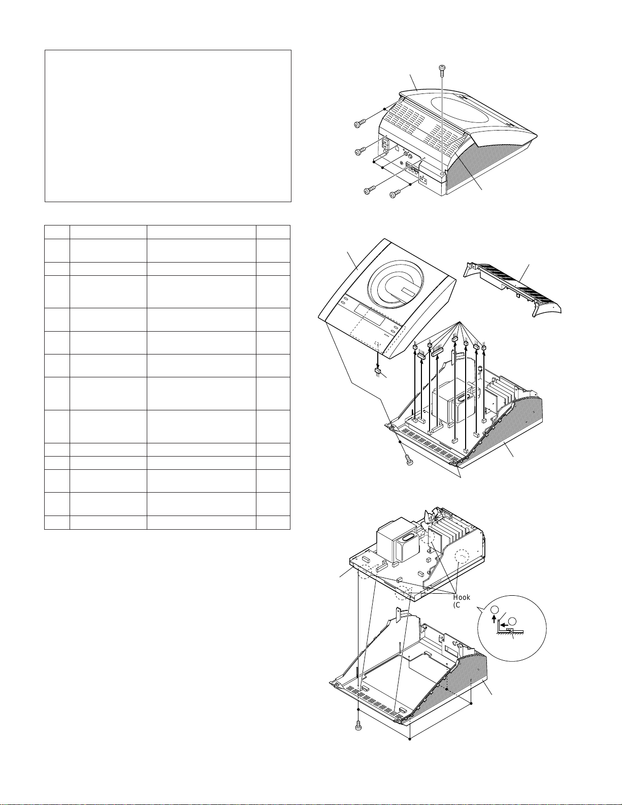
Screw
Laser Diode Properties
Material: GaAIAs
Wavelength: 780 nm
Emission Duration: continuous
Laser Output: max. 0.6 mW
VAROITUS! LAITTEEN KÄYTTÄMINEN MUULLA KUIN TÄSSÄ
KÄYTTÖOHJEESSA MAINITULLA TAVALLA SAATTAA
ALTISTAA KÄYTTÄJÄN TURVALLISUUSLUOKAN 1
YLITTÄVÄLLE NÄKYMÄTTÖMÄLLE LASERSÄTEILYLLE.
VARNING - OM APPARATEN ANVÄNDS PÅ ANNAT SÄTT ÄN
I DENNA BRUKSANVISNING SPECIFICERAS. KAN
ANVÄNDAREN UTSÄTTAS FÖR OSYNLIG LASER-
STRÅLNING, SOM ÖVERSKRIDER GRÄNSEN FÖR
LASERKLASS 1.
ADVERSEL-SYNLIG OG USYNLIG LASERSTRÅLING VED ÅBNING.
SE IKKE IND I STRÅLEN-HELLER IKKE MED OPTISKE INSTRUMENTER.
VARO!AVATTAESSAOLETALTTIINA NÄKYVÄLLE JANÄKYMÄTTÖMÄLLE
LASERSÄTEILYLLE ÄLÄ TUIJOTA SÄTEESEEN ÄLÄKÄ KATSO SITÄ
OPTISEN LAITTE EN LÄPI.
VARNING-SYNLIG OCH OSYNLIG LASERSTRÅLNING NÄR DENNA
DEL ÄR ÖPPNAD. STIRRA EJ IN I STRÅLEN OCH BETRAKTA EJ
STRÅLEN GENOM OPTISKT INSTRUMENT.


 User manual")