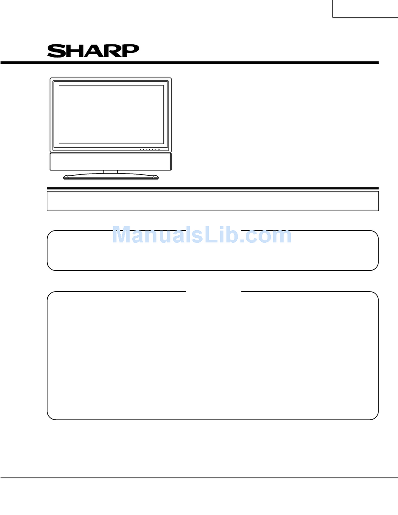
Sharp LC-32DV200E User manual

SERVICE MANUAL
S50OSLC32DV20
COMBINATION LIQUID CRYSTAL
TELEVISION AND DVD/CD PLAYER
MODEL
LC-32DV200E(K)
In the interests of user-safety (Required by safety regulations in some countries) theset should be restored
to its original condition and only parts identical to those specified should be used.
Page
• IMPORTANT WARNING …………………………………………………………………………………………………
…
A1-1
• SERVICING NOTICES ON CHECKING …………...…………………………………………………………………… A1-2
• HOW TO ORDER PARTS ………………...…………………………………………………………………………….
…
A1-2
• IMPORTANT ………………….………………………………………………………………………………………...…
…
A1-2
• WHEN REPLACING DVD DECK ………………………...……………………………………………………………
…
A1-3
• PREPARATION OF SERVICING……………………….………………………………………………………..……….A1-3
• DISC REMOVAL METHOD AT NO POWER SUPPLY …………………………………….…………………………
…
A1-4
• PARENTAL CONTROL - RATING LEVEL …………………………………….………………………………………
…
A1-4
• ABOUT LEAD FREE SOLDER (PbF) ………………………..……………………………………………………..…
…
A1-5
• HOTEL MODE FUNCTION………………………………...………………………...………………………………..…
…
A1-6
• GENERAL SPECIFICATIONS …………………………..………………………………………………………………
…
A2-1~A2-8
• DISASSEMBLY INSTRUCTIONS …………………………….……………………………………………………….… B1-1~B3-2
• SERVICE MODE LIST ……………………………………..……………………………………………………………
…
C-1
• SERVICING FIXTURES AND TOOLS …………………………………….……………………………………………
…
C-2
• RE-WRITE FOR DVD FIRMWARE ……………………………….……………………………………………………
…
C-2
• PART LOCATION GUIDE (WIRING CONNECTION) ……..…………………………………………………………
…
D-1
• TROUBLESHOOTING GUIDE ……………………..………………………………………………………………….… E-1~E-9
• BLOCK DIAGRAM ……………………………………..……………………………………………………………..…
…
F-1~F-12
• PRINTED CIRCUIT BOARDS ……………………….……………………………………………………………….…
…
G-1~G-11
• SCHEMATIC DIAGRAMS ……………………….…………………………………………………………………..…… H-1~H-50
• WAVEFORMS ………………………………………….…………………………………………………………….…… I-1~I-3
• MECHANICAL EXPLODED VIEWS ………………….…………………………………………………………………
…
J1-1~J1-3
• DVD DECK EXPLODED VIEWS ………………...……………………………………………………………..……..
…
J2-1
• REPLACEMENT PARTS LIST …………….…………………………………………………………………..……..…
…
K1-1~K3-8
Parts marked with " " are important for maintaining the safety of the set. Be sure to replace these parts with
specified ones for maintaining the safety and performance of the set.
SHARP CORPORATION
This document has been published to be used for
after sales service only.
CONTENTS
!

CAUTION:
DVD PLAYER IS A CLASS 1 LASER PRODUCT. HOWEVER THIS PLAYER USES A VISIBLE LASER
BEAM WHICH COULD CAUSE HAZARDOUS RADIATION EXPOSURE IF DIRECTED. BE SURE TO
OPERATE THE PLAYER CORRECTLY AS INSTRUCTED.
THE FOLLOWING CAUTION LABEL IS LOCATED ON THE REAR PANEL OF THE PLAYER.
(Printed on the Rear Panel)
WHEN THIS PLAYER IS PLUGGED TO THE WALL OUTLET, DO NOT PLACE YOUR EYES CLOSE
TO THE OPENING OF THE DISC TRAY AND OTHER OPENINGS TO LOOK INTO THE INSIDE OF
IMPORTANT WARNING
THIS PLAYER.
USE OF CONTROLS OR ADJUSTMENTS OR PERFORMANCE OF PROCEDURES OTHER THAN
THOSE SPECIFIED HEREIN MAY RESULT IN HAZARDOUS RADIATION EXPOSURE.
DO NOT OPEN COVERS AND DO NOT REPAIR YOURSELF. REFER SERVICING TO QUALIFIED
PERSONNEL.
A1-1

1. Remove the Stand Ass'y, Front Cabinet Ass'y and LCD Panel.
(Refer to item 1 of the DISASSEMBLY INSTRUCTIONS.)
2. Slide the Gear Middle toward the arrow direction by hand to release the lock. (Refer to Fig. 1)
3. Take out the Disc from the DVD Deck. Be careful not to scratch on the Disc.
DVD Deck
DISC REMOVAL METHOD AT NO POWER SUPPLY
Gear Middle
Fig. 1
If the stored 4 digit password in the Rating Level menu needs to be cancelled, please follow the steps below.
1. Turn Unit ON.
2. Set the DVD to the Stop Mode.
3. Check that “No disc” is displayed on the screen.
4. Press and hold the “STOP” button on the side panel.
5. Simultaneously press and hold the “7” key on the remote control unit.
6. Hold both keys for more than 2 seconds.
7. The On Screen Display message “PASSWORD CLEAR” will appear.
8. The 4 digit password has now been cleared.
PARENTAL CONTROL - RATING LEVEL
4 DIGIT PASSWORD CANCELLATION
Gear
Middle
A1-4

ABOUT LEAD FREE SOLDER (PbF)
Distinction of PbF PCB:
PCBs (manufactured) using lead free solder will have a PbF printing on the PCB.
(Please refer to figures.)
Caution:
Pb free solder has a higher melting point than standard solder;
Typically the melting point is 86oF~104oF(30oC~40oC) higher.
Please use a soldering iron with temperature control and adjust it to 650oF
±
20oF (350oC ±10oC).
In case of using high temperature soldering iron, please be careful not to heat too long.
Pb free solder will tend to splash when heated too high (about 1100
o
F/ 600
o
C).
A1-5
Pb free solder will tend to splash when heated too high (about 1100
o
F/ 600
o
C).
All products with the printed circuit board with PbF printing must be serviced with lead free solder.
When soldering or unsoldering, completely remove all of the solder from the pins or solder area,
and be sure to heat the soldering points with the lead free solder until it melts sufficiently.
Recommendations
Recommended lead free solder composition is Sn-3.0Ag-0.5Cu.
A1-5

HOTEL MODE FUNCTION
To reset the Hotel mode, please follow the steps below.
1.
Press the MENU---> 0027button on the remote control.
2.
The Hotel mode setting menu will appear.
3.
Using the UP/DOWN button on the remote control, select the RESET.
4.
Using the LEFT/RIGHT button on the remote control, please select "OK".
Then press the ENTER button.
5.
The setting items has now been returned to initial value.
Setting of the maximum volume value.
4.
Maximum volume
Setting item
5.
FUNCTIONInitial value
100
Setting value
0~100
To set the Hotel mode, please follow the steps below.
Press the MENU---> 0027 button on the remote control.
The Hotel mode setting menu will appear.
Using the UP/DOWN button on the remote control,
select the desired mode. Then press the ENTER button.
Using the LEFT/RIGHT button on the remote control,
1.
2.
3.
set the mode to desired setting.
The Hotel mode has now been set up.
Effective/invalid setting of main key operation. (*Note 1)
Effective/invalid setting of Menu key operation of set and remote control.
(*Note 1)
Note 1) Even if setting it to "No Respond", the service mode function are effective.
Note 2) If setting it to "OFF", it start up in same input source when you turn off the power before.
Panel button
Setting of input source at power supply On. (*Note 2)
COMPONENT/
Input mode start
Menu button RESPOND
OFF
RESPOND/
NO RESPOND
TV/AV/
Reset Various settings of the Hotel mode function return initial State.
All Channel 1
HDMI/PC/DVD/
OFF
Channel Number Channel Number tuned when starting this product can be set.
A1-6

GENERAL SPECIFICATIONS
G-1 TV LCD LCD Size / Visual Size 31.51 inch / 800.4mmV
System LCD Type Color TFT LCD
Number of Pixels 1366(H) x 768(V)
View Range Left/Right 88/88 degree
Up/Down 89/89 degree
Bright Dot n 0
Zero Bright Dot Ratio --
Color System PAL / SECAM
Speaker 2 Speaker
Position Front
Size 1.6 x 4.8 inch
Impedance 4 ohm
Sound Output MAX 10W + 10W
10%(Typical) ---
NTSC3.58+4.43 /PAL60Hz Yes
G-2 DVD System Color System NTSC, PAL
Disc DVD,
Disc Diameter 120 mm , 80 mm
Drive DSM-4
Search speed Fwd 4 step
Actual 4, 8, 16, 32 times (DVD)
4, 8, 16, 32 times (CD)
Rev 4 step
Actual 4, 8, 16, 32 times (DVD)
4, 8, 16, 32 times (CD)
Slow speed Fwd 4 step
Actual 1/16, 1/8, 1/4, 1/2 times
Rev 4 step
Actual 1/16, 1/8, 1/4, 1/2 times
G-3 Tuning Broadcasting System Analog U.K.,
System Digital DVB-
Tuner and System 1Tuner (Analog+Digital)
Receive CH Destination UK, I.R., CCIR Hyper+France CATV
CH Coverage Analog IreE2~E4, X~Z+2, S1~S10, E5~E12,S11~S41,E21~E69
Digital E5~E12, ItaD~H2, Fra1~6, Rus6~12, E21~E69
Intermediate Analog BG / II
Frequency Picture(FP) 38.9 / 38.9 / 38.9 / 33.9MHz
Sound(FS) 33.4 / 32.9 / 32.4 / 40.4MHz
FP-FS 5.5 / 6.0 / 6.5 / 6.5MHz
Digital 36.167MHz
Auto Tuning Method ALL Band (Not C.C.I.R. CH Plan)
Preset CH 2000 Service in total of Analog and Digital.
Stereo/Dual TV Sound Nicam/A2 Dual
Tuner Sound Muting Yes
G-4 Signal Video Signal Input Level 1 V p-p/75 ohm
Output Level 1 V p-p/75 ohm
S/N Ratio (Weighted) 65dB
Horizontal Resolution at DVD Mode 400 Lines
RGB Signal Output Level --
Audio Signal Input Level -8.0dBm/50k ohm
Output Level at DVD -12.0dBm/1k ohm (-20dBFs 0dBFs=2.0Vrms)
at TV -8 dBm/1k ohm (0dBm=0.775Vrms)
Digital Output Level 0.5 V p-p/75 ohm
S/N Ratio at DVD (Weighted) 85dB
Harmonic Distortion 0.02% (1KHz)
Frequency Response : at DVD 4Hz - 22kHz
at Video CD/SVCD 4Hz - 20kHz
at CD 4Hz - 20kHz
G-5 Power Power Source AC 220-240V AC 50Hz
DC ---
Power Consumption at AC 95 W at AC 230 V 50 Hz
at DC --
Stand by (at AC) w/ EPG Timer --
w/o EPG Timer 0.5 W at AC 230 V 50 Hz
Per Year -- kWh/Year
Protector Power Fuse Yes
<
=
A2-1
GENERAL SPECIFICATIONS
G-6 Regulation Safety CE(EN60065:2002+AMD.11:2008), SEMKO, HOMOLO,
Ukraine Safety
Radiation CE
X-Radiation ---
G-7 Temperature Operation +5oC ~ +40oC
Storage -20oC ~ +60oC
Space Around Unit 100mm (4inch)
G-8 Operating Humidity Less than 80% RH
G-9 OSD Language (TV) English, Spanish, German, French, Italian, Swedish
Dutch, Russian, Portuguese, Turkish, Greek, Finnish
Polish, Danish, Norwegian, Hungarian, Czech, Slovak
Estonian, Latvian, Lithuanian, Slovenian, Ukranian
(DVD) English, Spanish, German, French, Italian, Swedish
Dutch, Russian, Portuguese, Turkish, Greek, Finnish
Polish, Danish, Norwegian, Hungarian, Czech, Slovak
Estonian, Latvian, Lithuanian, Slovenian, Ukranian
G-10 Clock and Sleep Timer Max Time 120 Min
Timer Step 10 / 20 / 30 / 40 / 50 / 60 / 90 / 120 Min
On/Off Timer Program(On Timer / Off Timer) 1 Program / 1 Program
Timer Back-up (at Power Off Mode) more than -- Min Sec
EPG Timer Events --
G-11 Remote Unit RC-RV
Control Glow in Dark Remocon No
Remocon Format ORION
Format NEC
Custom Code 71-8E h
Power Source Voltage(D.C) 3V
UM size x pcs UM-3 x 2 pcs
Total Keys 47 Keys
Keys Power (Stand By) Yes
Display / (Status) Yes
Analog Menu No
Digital Menu No
Input Select Yes
DTV/ATV Yes
TV/DVD Yes
Eject No
Guide(EPG) Yes
Picture Size Yes
1 Yes
2 Yes
3 Yes
4 Yes
5 Yes
6 Yes
7 Yes
8 Yes
9 Yes
0 Yes
Sleep No
Mute Yes
Volume Up / No
Volume Down / No
Volume Up Yes
Volume Down Yes
CH Down No
CH Up No
Menu / Setup Yes
A2-2

GENERAL SPECIFICATIONS
Yes
Yes
/Slow- Yes
/Slow+ Yes
OK / CH List Yes
Return Yes
Freeze No
TV/Radio No
Subtitle Yes
Audio No
Play Yes
Stop Yes
Pause Yes
Quick View Yes
Cancel Yes
DVD Menu Yes
Top Menu Yes
Repeat A-B No
Play Mode Yes
Jump No
Search+ No
Search- No
T'TEXT Keys TEXT / TAP / TV Yes
Slow+ / F.T.B No
Audio / F.T.B Yes
Slow- / Hold No
Freeze / Hold Yes
Angle / Reveal Yes
Zoom / Sub Page Yes
Red/Skip- Yes
Green/REV Yes
Yellow/FWD Yes
Cyan/Skip+ Yes
CH Up / Page Up Yes
CH Down / Page Down Yes
G-12 Features Power On Memory Yes
Auto Shut Off Yes
Just Clock Function No
Game Position No
DNR Yes
3D
Comb Filter Yes
3D
Auto Set Up (Fast installation) Auto tuning Yes
CH sort Yes
ATS Yes
Auto clock (Digital tuner) Yes
Plug in start Yes
Picture Setting(TV) Picture Preference Yes
Brightness , Contrast , Color Yes
Tint Yes
Sharpness Yes
DNR Yes
Color Temperature Yes
Blue Back Yes
Backlight Control Yes
HDMI Mode Yes
DBC (Dynamic Backlight Control) Yes
Film Mode No
Picture Setting(PC) BRIGHTNESS , CONTRAST Yes (Connected with TV mode setting)
HOR POSITION , VER POSITION Yes
PHASE , CLOCK Yes
AUTO ADJUST Yes
RED , GREEN , BLUE Yes
Backlight Yes (Connected with TV mode setting)
WXGA INPUT No
WVGA INPUT No
A2-3

GENERAL SPECIFICATIONS
Audio Tone Control (Bass/Treble/Balance) Yes
Surround Yes
Equalizer Yes
Speaker Yes
Stable Sound No
Audio Description Yes
BBE No
SRS WOW (SRS 3D/Focus/Tru Bass) No
Variable Audio Out No
Tuning Auto Tuning (Analog/Digital) Yes
Update Scan (Analog/Digital) Yes
CH Skip (Analog/Digital) Yes
CH Sort (Analog/Digital) Yes
CH Edit (Analog/Digital) Yes
Fine Tuning (Analog) Yes
Lock Panel Lock No
Channel Lock Yes
Parental Lock (Digital) Yes
Hotel Lock Yes
Screen Saver Inversion No
Full White No
Screen Saver No
Static Image No
T'Text Yes
Text type Fastext / Toptext
Text Language English, German, Swedish, Finnish, Hungarian,
Italian, French, Portuguese, Spanish, Czech,
Slovak, Polish, Estonian, Lettish, Lithuanian,
Serbian, Croatian, Slovenian, Rumanian, Russian,
Bulgarian, Ukrainian, Turkish, Greek, Hebrew,
Arabic
Text and Picture Yes
Wide Mode (AUTO/4:3/16:9/CINEMA/14:9/REAL) Yes
CH Label Yes
Reset TV Setting Yes
HD Zoom Yes
Picture Scroll (Vertical Position) No
PFC(Power Factor circuit) Yes
Freeze frame Yes (Tuner Only)
Plug and Play No
Power Management Yes
No Operation Power Off Yes
Hearing Impaired Yes
4:3 Mode (Auto 4:3 Default) Yes
TV Location Yes
Scart Spec Scart1 AV in Yes
AV out Yes (A.Tuner/D.Tuner)
S-Video in Yes
RGB in Yes
Scart2 AV in Yes
AV out Yes (Monitor)
S-Video in Yes
RGB in No
Digital Text (VBI teletext) Yes
MHEG-5 Yes
MHP No
EPG (BBC type 8Days Digital tuner only) Yes
OAD (Over Air Download) Yes
Common Interface (Digital tuner only) Yes
Rec Screen Status No
Ch sorting based on Ch List (Digital/Germany only) Yes
Rename Carrier (Digital) No
Edit Event Timer No
Software Update via CI Slot No
Preference Language (Audio/Subtitle/Digital Service)(Digital) Yes
DVB Subtitle (Digital) Yes
Time Setup Yes
Signal Status Yes
A2-4

GENERAL SPECIFICATIONS
Digital Out Dolby Digital Dolby Digital
Dolby Digital Plus Dolby Digital
MPEG PCM
HE AAC Dolby Digital
Decode(Down Mix) Dolby Digital Yes
Dolby Digital Plus Yes
MPEG Yes
HE AAC Yes
PC Monitor Input Yes
VGA (640x480) Yes (60Hz)
VGA (720x400) No (Possible to Display)
WVGA (848x480) No
SVGA (800x600) Yes (60Hz)
XGA (1024x768) Yes (60Hz)
WXGA (1280x768) Yes (60Hz)
WXGA (1280x720) Yes (60Hz)
WXGA (1360x768) Yes (60Hz)
SXGA (1280x1024) No (Possible to Display)
WXGA+ (1440x900) No (Possible to Display)
WSXGA+ (1680x1050) No (Possible to Display)
FULL HD (1920x1080) No (Possible to Display)
HDMI Input Yes
VGA (640×480) Yes (60Hz)
VGA (720x400) No (Possible to Display)
WVGA (848x480) No
SVGA (800x600) Yes (60Hz)
XGA (1024x768) Yes (60Hz)
WXGA (1280x768) Yes (60Hz)
WXGA (1280x720) Yes (60Hz)
WXGA (1360x768) Yes (60Hz)
SXGA (1280x1024) No (Possible to Display)
WXGA+ (1440x900) No (Possible to Display)
WSXGA+ (1680x1050) No (Possible to Display)
FULL HD (1920x1080) No (Possible to Display)
720×480i (4:3) Yes (60Hz)
720×480i (16:9) Yes (60Hz)
720×480p (4:3) Yes (60Hz)
720×480p (16:9) Yes (60Hz)
720×576i (4:3) Yes (50Hz)
720×576i (16:9) Yes (50Hz)
720×576p (4:3) Yes (50Hz)
720×576p (16:9) Yes (50Hz)
1280×720p Yes (50/60Hz)
1920×1080i Yes (50/60Hz)
1920×1080p Yes (24/50/60Hz)
CEC(ORION Standard) No
Deep Color No
xvYCC No
Component Input Yes
720×480i (4:3) Yes (60Hz)
720×480i (16:9) Yes (60Hz)
720×480p (4:3) Yes (60Hz)
720×480p (16:9) Yes (60Hz)
720×576i (4:3) Yes (50Hz)
720×576i (16:9) Yes (50Hz)
720×576p (4:3) Yes (50Hz)
720×576p (16:9) Yes (50Hz)
1280×720p Yes (50/60Hz)
1920×1080i Yes (50/60Hz)
1920×1080p No (Possible to Display)
Wall Mount Size W x H(mm) Yes (200 x 200)
Screw Size M6 x 10
Stand Tilt No
Swievel No
A2-5

GENERAL SPECIFICATIONS
Features Parental Lock Yes
(DVD) Auto Power Off No
Video CD Playback Yes
SVCD Playback Yes
MP3 Playback Yes
WMA Playback Yes
JPEG Playback Yes
Fujicolor CD Yes
KODAK Picture CD Yes
Divx Playback Yes
DMF Support No
VR Format Pla
y
b
a
No
USB No
Digital Out Dolby Digital Dolby Digital
MPEG PCM
PCM PCM
DTS Yes
Decode(Down Mix) Dolby Digital Yes
DTS No
Auto Retract Disc No
BNR No
Disc Navigator Yes
E.B.L. (Enhanced Black Level) No
Surround No
Screen Saver No
Tray Lock No
One Touch Replay No
CGMS-A in CC XDS No
Audio DAC 192kHz / 24bit
Macrovision Yes (No Video Out)
Closed Caption signal in VBI (DVD Playback) No
Play Mode Yes
Audio Adjust Yes
Equalizer Yes
Dynamic Range Control Yes
Dialog Yes
Video Adjust Yes
Sharpness Yes
Brightness Yes
Contrast Yes
Gamma Yes
Hue Yes
Chroma Level Yes
TV Screen 4:3 (Letter Box, Pan Scan) Yes
16:9 (Wide) Yes
Audio Language Yes
Subtitle Language Yes
DVD Menu Language Yes
Subtitle Display Yes
Angle Indicator Yes
G-13 Accessories Owner's Manual Language English, Spanish, German, French, Italian, Portuguese
Dutch
w/Guarantee Card No
Remote Control Unit Yes
Rod Antenna No
Poles -
Terminal -
Loop Antenna (W/ Antenna Change Plug) No
Terminal -
A2-6

GENERAL SPECIFICATIONS
DVB-T Antenna No
U/V Mixer No
DC Car Cord (Center+) No
Guarantee Card Yes
Caution Sheet No
Repair Coupon No
AQUOS Care plan Yes
Warning Sheet No
Circuit Diagram No
Antenna Change Plug No
Service Facility List No
Important Safeguard No
Quick Set-up Sheet Yes(11Language)
Battery Yes
UM size x pcs UM-3 x 2 pcs
OEM Brand No
AC Adapter No
AC Cord (for AC Adapter) No
AC Cord Yes
AV Cord (2Pin-1Pin) No
HDMI-DVI Cable No
Registration Card No
300 ohm to 75 ohm Antenna Adapter No
Stand Screw??? Yes(8pcs,Wrench)
Stand Yes
Frame Stand Yes
G-14 Interface Switch Side Power (Tact) Yes
System Select No
Main Power SW No
Channel Up / Play / Menu Up Yes
Channel Down / Stop / Menu Down Yes
Volume Up/Menu > Yes
Volume Down/Menu < Yes
Input Select/Enter Yes
Menu Yes
Eject Yes
Indicator Power/Stand-by Yes(GREEN / RED)
On Timer No
Terminals Rear Video Input 1 RCA x 1 (AV3)
Audio Input 1 RCA x 2(L/MONO, R) (AV3)
S- Input 1 No
Video Input 2 No
Audio Input 2 No
S- Input 2 No
Video Output No
Audio Output No
Digital Audio Out (Coaxial) Yes
Headphone No
Euro Scart (21Pin) 2Scart (AV1, AV2)
Component In RCA x 3
Audio Input (Component In use) RCA x 2(L/MONO, R)
PC Monitor Input (D-Sub) Yes
Audio Input Mini Pin Jack( 3.5), STEREO
HDMI Input 1 Yes
Audio Input (HDMI/DVI In use) PC Monitor Audio Input Alternative
HDMI Input 2 Yes
Audio Input (HDMI/DVI In use) No
HDMI Input 3 No
Audio Input (HDMI/DVI In use) No
USB(Software Update) Yes
Sub Woofer Output No
Diversity No
Ext Speaker No
DC Jack 12V(Center +) No
AC Inlet Yes
VHF/UHF Antenna Input No
Side CI Card Slot Yes
Headphone Yes
VHF/UHF Antenna Input DIN Type
A2-7

GENERAL SPECIFICATIONS
G-15 Set Size Approx. W x D x H (mm) 796.2 x 243.0 x 596.6
w/o Stand,Handle Approx. W x D x H (mm) 796.2 x 105.5 x 546.6
G-16 Weight Net Approx. 12.5kg (27.2lbs)
Net w/o Stand,Handle Approx. 11.0kg (24.1lbs)
Gross Approx. 15.5kg (34.4lbs)
Gross w/Master Carton (Approx.) --- kg ( --- lbs)
G-17 Carton Master Carton No
Content ---- Sets
Material -- /--
Dimensions W x D x H(mm) -- x -- x --
Description of Origin No
Gift Box Yes
Material Double/Brown
Dimensions W x D x H(mm) 900 x 265 x 654
Design As per Buyer's
Description of Origin No
Drop Test Natural Dropping At 1 Corner / 3 Edges / 6 Surfaces
Height (cm) 48
Container Stuffing 390 Sets/45' Trailer
w/Pallet No
w/Wrapping No
G-18 Material Cabinet Cabinet Front PC+ABS 94V0 NON-HALOGEN
Cabinet Rear PS 94V0 NON-DECABROM
Stand PC+ABS 94V0 NON-HALOGEN
PCB Non-Halogen No
Eyelet Yes
G-19 Environment Environmental standard requirement Green procurement of SHARP
Pb- Free Phase3(PHASE3A)
Measures for Whisker Yes
WEEE Yes
A2-8

1. REMOVAL OF MECHANICAL PARTS
AND P.C. BOARD
S
1. Remove the 12 screws (1).
2. Remove the Back Cabinet Ass'y in the direction of arrow .
CAUTION
Be careful not to remove the LVDS cable forcibly, because
the LVDS cable may be damaged.
1-1: COVER INVERTER and COVER LVDS
(
Refer to Fi
g
. 1-1
)
1. Remove the screws (1).
2. Remove the Cover Inverter in the direction of arrow (A)
.
3. Disconnect the followin
g
connectors:
(
CP3803
)
.
4. Remove the screws (2).
5. Remove the Cover LVDS in the direction of arrow (B)
.
6. Release the lock of connector disconnect the followin
g
connector: (CP2804).
DISASSEMBLY INSTRUCTIONS
1-2: BACK CABINET ASS'Y (Refer to Fig. 1-2)
(1)
(2)
(A)
Back Cabinet Ass'y
(B)
Connector
Cover
Cover LVDS
(1)
(1)
(1)
(1)
(1)
(1)
(1)
(1) (1) (1) (1)(1)
Front Cabinet
(1)
(1)
B1-1
1. Remove the 4 screws (1).
2. Remove the Angle-Hinge in the direction of arrow (A).
3. Remove the 5 screws (2).
4. Remove the Angle-LCD Bottom in the direction of arrow (B).
5. Remove the LCD Block in the direction of arrow (C).
1-3: LCD BLOCK
(
Refer to Fi
g
. 1-3
)
Fig. 1-1
LVDS
Fig. 1-3
Front Cabinet Ass'y
(C)
Fig. 1-2
LCD Block
(B)
(1)
(1)
(2) (1)
(1)
(2)
(2)
Angle-LCD-Bottom (A)
(1)
Angle-Hinge
(2)
B1-1

1-4: DVD MT PCB and DVD DECK
(
Refer to Fi
g
. 1-4
)
1-5: POWER PCB
(
Refer to Fi
g
. 1-5
)
1. Put the Cabinet Back Ass'y on the bottom. 1. Disconnect the following connectors:
2. Short circuit the position shown in Fig. 1-4 using a
(
CP3200 and CP3203
)
.
soldering iron. If you remove the DVD Deck with no 2. Remove the 6 screws (1).
soldering, the Laser may be damaged. 3. Remove the Power PCB in the direction of arrow.
3. Disconnect the following connectors:
(
CP2301, CP2302, CP2303, CP8501 and CP8502
).
4. Remove the 3 screws (1).
5. Remove the DVD DECK Ass'y in the direction of
arrow (A).
6. Remove the 4 screws (2).
7. Unlock the 2 supports (3).
8. Remove the DVD MT PCB in the direction of arrow (B).
9. Remove the Shield LVDS in the direction of arrow (C).
10. Remove the Shield LVDS Bottom in the direction of arrow (D).
DISASSEMBLY INSTRUCTIONS
Power PCB
(1)
(1)
(1)
(A)
(1)
(C)
Shield LVDS
DVD MT PCB
Short circuit using a
ld i i
Pick Up PCB
(1)
(1)
(1)(1)
Fig. 1-5
Back Cabinet Ass'y
(2)
(1)
Shield LVDS
(2)
(2)(2)
(B)
(D)
(3)
(3)
B1-2
1-6: MAIN PCB and TUNER PCB
(
Refer to Fi
g
. 1-6
)
1. Disconnect the following connector:
(
CP301, CP2201and CP4301
).
2. Remove the 2 screws (1).
3. Remove the Tuner PCB in the direction of arrow (A).
4. Remove the screw (2).
5. Remove the Spring Earth Tuner in the direction of arrow (B).
6. Remove the 3 screws (3).
7. Remove the Shield Main Bottom in the direction of arrow (C
)
8. Remove the 6 screws (4).
NOTE 9. Remove the Main PCB in the direction of arrow
(
D
).
10. Remove the Plate Jack in the direction of arrow (E).
1. Before your operation, please read "PREPARATION
OF SERVICING".
2. Use the Lead Free solder.
3. Manual soldering conditions
•
Soldering temperature: 320 ± 20
o
C
• Soldering time: Within 3 seconds
• Soldering combination: Sn-3.0Ag-0.5Cu
4. When Soldering/Removing of solder, use the drawing
equipment over the Pick Up Unit to keep the Flux
smoke away from it.
5. When installing the DVD Deck, remove all the soldering
on the short circuit position after the connection of Pick
Up PCB and DVD MT PCB connector. Main PCB
Back Cabinet Ass'y
Fig. 1-6
(4)
Back Cabinet Ass'y
so
ld
er
i
ng
i
ron.
Fig. 1-4
(1)
(2)
(1) (3)
(4)
(4)
(3)
(3)
Tuner PCB
Spring EarthTuner
Shield Main
Bottom
(4)
(4)
(4)
Plate Jack
(B)
(A)
(C)
(D)
(E)
B1-2

1-7: OPERATION PCB and REMOCON PCB
(
Refer to Fi
g
. 1-7
)
1. Remove the 2 screw (1).
2. Remove the Remocon PCB in the direction of arrow (A).
3. Remove the 2 screws (2).
4. Remove the Panel Side Ass'y in the direction of arrow (B).
5. Remove the 3 screws (3).
6. Remove the Operation PCB in the direction of arrow (C).
DISASSEMBLY INSTRUCTIONS
(A) (B)
Back Cabinet Ass'y
(1)
Remocon PCB (1)
(3)
(2)
(2) (C)
Operation PCB
(3)
(3)
(3)
Panel Side
B1-3
Fig. 1-7
B1-3

2. REMOVAL OF DVD DECK PART
S
NOTE
1. Disassemble only the DVD DECK PARTS parts listed
here. Minute adjustments are needed if the
disassembly is done. If the repair is needed except
listed parts, replace the DVD MECHA ASS'Y.
2-1: TRAVERSE ASS'Y/LOADING MOTOR PCB ASS'Y/
PLATE TRVS UD (Refer to Fig. 2-1-A)
1. Remove the screw (1).
2. Remove the screw (2). 2.2: INSULATOR (R)/FEED RACK ASS'Y/
3. Unlock the 5 supports (3). PCB630/GEAR MIDDLE/GEAR FEED/
4. Remove the Insulator (R) from the Loader Ass'y. FEED MOTOR/GEAR MOTOR
5. Remove the Traverse Ass'y and Plate Trvs Ud. (Refer to Fig. 2-2-A)
1. Remove the Insulator (R).
2. Remove the screw (1).
3. Remove the Feed Rack Ass'y.
4. Unlock the 2 supports (2).
5. Remove the PCB630.
6. Remove the screw (3).
7. Remove the Gear Feed.
8. Remove the Gear Middle.
9.
Remove the 2 screws (4).
DISASSEMBLY INSTRUCTIONS
Traverse Ass'y
Insulator (R)
(1)
(2)
Plate TRVS UD
(
3
)
(
3
)
Fig. 2-1-C
Check Lock
B2-1
9
.
Remove
the
2
screws
(4)
.
10. Remove the Gear Motor.
11. Remove the Feed Motor.
• Screw Torque: 1.0 ± 0.3kgf•cm (screw(1))
• Screw Torque: 3.0 ± 0.3kgf•cm (screw(2))
NOTE
1. In case of the Traverse Ass'y installation, hook the wire
on the Loader Ass'y as shown Fig. 2-1-B to Fig. 2-1-C.
• Screw Torque: 1.3 ± 0.3kgf•cm (Screw (1))
• Screw Torque: 2.5 ± 0.3kgf•cm (Screw (3))
• Screw Torque: 1.0 ± 0.3kgf•cm (Screw (4))
Loader Ass'y (Top side)
Loader Sub Ass'y
(
)
(3)
(
3
)
Fig. 2-1-A
Fig. 2-1-B
Check Lock
Check Lock
Check Lock
(3)
Chassis
Feed Motor
Gear Middle
(4)
(3)
Gear Feed
(2)
(1)
PCB630
Feed Rack Ass'y
Gear Motor
Fig. 2-2-A
Insulator (R)
B2-1

NOTE
1. In case of the Gear Motor installation, check if the value
of the Fig. 2-2-B is correct.
2. When installing the wire of the PCB630 install it correctly
as Fig. 2-2-C.
Manual soldering conditions
• Solderin
g
tem
p
erature: 350 ± 5oC
• Soldering time: Within 4 seconds
• Soldering combination: Sn-3.0Ag-0.5Cu
3. When installing the Feed Rack Ass'y, push both ends to
align the teeth as shown Fig. 2-2-D. Then install it.
4. In case of the Insulator (R) installation, install correctly as
Fig. 2-2-E.
5. After the assembly of the Traverse Ass'y, hook the wire
on the Traverse Ass'y as shown Fig. 2-2-F.
• In case of remove FEED MOTOR that has to arrange wire as following
7.0 ± 0.1mm the picture on above.
2.3: GEAR ROLLER/LUMIRROR WASHER/
ROLLER CONE/SHAFT ROLLER/
LOADING MOTOR PCB/LOADING MOTOR/
GEAR WORM/RACK LEVER (Refer to Fig. 2-3-B)
DISASSEMBLY INSTRUCTIONS
Insulator (R)
Gear Motor
Feed Motor
Safety surface for pressing of the insert.
Fig. 2-2-B
Fig. 2-2-E
Traverse Ass'y (Top Side)
Fig. 2-2-F
Check Hook
Traverse Ass'y
Check Hook
UP SIDE
BOTTOM
B2-2
1. Remove the 3 screws (1).
~FEED MOTOR~
2. Remove the Chassis Main Ass'y.
3. Remove the Roller Ass'y.
4. Remove the Gear Roller.
5. Remove the Lumirror Washer.
• Install wire from (1) to (4) in order.
6. Remove the Roller Cone.
7. Remove the Shaft Roller .
8. Remove the screw (2).
9. Remove the Loading Motor PCB Ass'y.
10. Remove the screw (3).
11. Remove the Loading Motor.
12. Remove the Gear Worm.
13. Remove the Rack Lever.
NOTE
1. When Chassis Main Ass'y is removed, it is necessary to
change the position of Lever Disc and Guide Disc.
2. In case of the Chassis Main Ass'y, check position Lever
Disc, Lever Guide and Boss of Rack Disc Sensor as shown
Feed Rack Ass'y Fig. 2-3-A.
• Remove the Lever Guide in the direction of arrow.
(OK) (NG)
PCB630
Fig. 2-2-C
Push Push
Fig. 2-2-D
~FEED MOTOR~
WHITE(3)
BROWN(4)
GREEN(1)
YELLOW(2)
Fig. 2-3-A
Check Boss
Check Position
Chassis Main Ass'y
Frame Main Ass'y
Lever Guide
B2-2

• Install wire from (1) to (2) in order.
RED(2)
BLACK(1)
(OK) (NG)
• Screw Torque: 3.0 ± 0.3kgf•cm (Screw (1))
• Screw Tor
q
ue: 0.8 ± 0.3k
g
f•cm
(
Screw
(
2
))
DISASSEMBLY INSTRUCTIONS
Loading Motor PCB Ass'y
Lumirror Washer
Roller Cone
Rack Lever
Shaft Roller
Roller Cone
Lumirror Washer
Gear Roller
Chassis Main Ass'y
Frame Main Ass'y
(1)
(1) (1)
(3)
Loading Motor
Gear Worm
(2)
Loading Motor PCB Ass'y
Fig. 2-3-D
Roller Sub Ass'y
Fig. 2-3-E
Roller Sub Ass'y
B2-3
•
Screw
Torque:
0
.
8
±
0
.
3kgf•cm
(Screw
(2))
• Screw Torque: 1.0 ± 0.3kgf•cm (Screw (3)) (OK) (NG)
NOTE
1. In case of the Gear Worm installation, check if the value
of the Fig. 2-3-C is correct.
2. When installing the wire of the Loading Motor PCB Ass'y,
install it correctly as Fig. 2-3-D.
Manual soldering conditions
• Solderin
g
tem
p
erature: 350 ± 5oC
• Soldering time: Within 4 seconds
• Soldering combination: Sn-3.0Ag-0.5Cu
3. In case of the Roller Cone installation, install correctly as
Fig. 2-3-E.
4. In case of the Lumirror Washer installation,
install correctly as Fig. 2-3-F. 1.8 + 0, - 0.1mm
5. In case of the Gear Roller installation, check if the value
of the Fig. 2-3-G is correct.
6. After the assembly of the Loader Sub Ass'y, hook the wire
on the Loader Sub Ass'y as shown Fig. 2-3-H.
14.3 + 0, - 0.1mm
Loader Sub Ass'y
Fig. 2-3-B
Gear Worm
Loading Motor
Safety surface for pressing of the insert. Fig. 2-3-C
Fig. 2-3-G
Roller Sub Ass'y
Fig. 2-3-F
Fig. 2-3-H
Check Hook
Check Hook
Safety surface for
pressing of the insert.
B2-3

2.4: SPRING SHUTTER/PLATE RETAINER/
RETAINER SHUTTER/COVER CLAMPER/
PLATE CLAMPER/MAGNET CLAMPER/
CLAMPER/GUIDE DISC/LEVER DISC/
SPRING LEVER GUIDE/SPRING LEVER DISC/
LEVER DISC (Refer to Fig. 2-4-A)
1. Unlock the support (1).
2. Remove the Retainer Shutter Ass'y.
3. Remove the Spring Shutter.
4. Remove the 3 screws (2).
5. Remove the Plate Retainer.
6. Remove the Retainer Shutter.
7. Unlock the 2 supports (3).
8. Remove the Cover Clamper.
9. Unlock the 3 supports (4).
10. Remove the Plate Clamper. (OK) (NG)
11. Remove the Magnet Clamper.
12. Remove the Clamper.
13. Unlock the support (5).
14. Remove the Guide Disc.
15. Remove the Lever Guide.
16. Remove the Spring Lever Guide.
17. Remove the Spring Lever Disc.
18. Remove the Lever Disc.
DISASSEMBLY INSTRUCTIONS
Spring Shutter (2pcs)
Clamper Ass'y
Fig. 2-4-B
Check Hook
Frame Main Ass'y
Retainer Shutter
B2-4
2-5: FFC WIRE HANDLING
1. When installing the FFC, fold it correctly and install it as
shown from Fig. 2-5-A to Fig. 2-5-D.
NOTE
1. Do not make the folding lines except the specified
positions for the FFC.
• Screw Torque: 0.7 ± 0.3kgf•cm (Screw (2))
NOTE 35 ± 1mm
1. In case of the Retainer Shutter Ass'y installation,
check if the value of the Fig. 2-4-B is correct. Fold
2. In case of the Clamper Ass'y installation,
check if the value of the Fig. 2-4-C is correct.
[ 22 pin FFC ]
Guide Disc
Frame Mian
Spring Lever Disc
(5)
(2)
Lever Disc
Lever Guide
Spring Lever Guide
Cover Clamper
Plate Clamper
Magnet Clamper
Clamper
(2)
(2)
Retainer Shutter
Spring Shutter
Fig. 2-4-A
Fig. 2-4-C
Fig. 2-5-A
Printing Surface
Plate Retainer
(1)
(3)
(4)
Check Hook
B2-4
This manual suits for next models
1
Table of contents
Other Sharp TV manuals

Sharp
Sharp SX-68JS7 SX-68JS9 User manual

Sharp
Sharp 20F-S40 User manual

Sharp
Sharp 32HW-57E ES User manual

Sharp
Sharp Aquos UQ17U User manual

Sharp
Sharp 21V-R70M User manual

Sharp
Sharp LC-20B2UA User manual

Sharp
Sharp LC-32HI5012E User manual

Sharp
Sharp LC-32HT2U User manual

Sharp
Sharp 32UC4 User manual

Sharp
Sharp 32K-X2000 User manual

Sharp
Sharp 32F631 User manual

Sharp
Sharp 70GS-62S User manual

Sharp
Sharp DV-7035S User manual

Sharp
Sharp 70GF-63E User manual

Sharp
Sharp 14LK20A User manual

Sharp
Sharp 25R-M100 User manual

Sharp
Sharp LC-22DV510E User manual

Sharp
Sharp 21HS-50N User manual

Sharp
Sharp 63CS-03S User manual

Sharp
Sharp 21HT-15CS User manual