2701 Busse Road Elk Groove Village, IL. 60007 Tel. 708-562-9221
IM-N66-0
August 8, 2013
Page 3 of 5
---WARNING---
Do not attempt to repair or partially disassemble a valve while it is in line and under pressure.
Isolate the line, de-pressurized, and remove valve prior to performing maintenance.
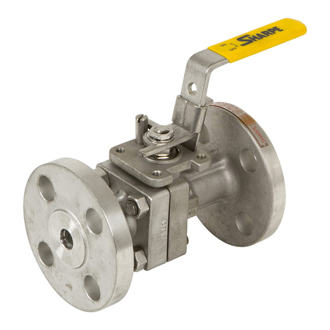
1. Turn valve to open position and remove the handle nut, lock washer, and handle.
2. Remove lock tab, stem nut, Belleville springs, and gland ring.
3. Loosen the body bolts, remove the end caps, body bolts, seals, and seats.
4. To take out the ball, rotate stem so ball is in fully closed position. Carefully lift ball off
stem tang and from body with a “rolling” motion. Note: Extreme caution should be
taken to avoid damage to the ball.
5. Push the stem downwards and slide it out from the body. The thrust bearing should
come out with the stem. Then remove the stem packing.
VISUAL INSPECTION:
1. Clean and inspect all metal parts. Replace the ball and/or stem if the seating or sealing
surfaces have been damaged, worn, or corroded.
2. Stem seals, seats, and body seal must be replaced whenever the valve is
disassembled to avoid seal leakage and ensure proper performance. Use only Sharpe
Valves replacement parts.
ASSEMBLY:
Note: The valve may be assembled and operated dry where no lubricants are allowed in the
system; however, a light lubrication of mating parts will aid in assembly and reduce initial
operating torque. Lubricant used must be compatible with the intended line fluid.
1. Install thrust bearing on stem and slide the stem up through the body.
2. Install new stem seals, gland ring, and belleville springs. Install gland nut and tighten
using the torque values given in Table 1.
