manuals.online logo
Brands
  1. Home
  2. •
  3. Brands
  4. •
  5. Sanhua
  6. •
  7. Control Unit
  8. •
  9. Sanhua MDF Series User manual

Sanhua MDF Series User manual

INSTRUCTIONS
Copyright © SANHUA 2020 1 II-MDF-MU-R2010
Subject to change without notice
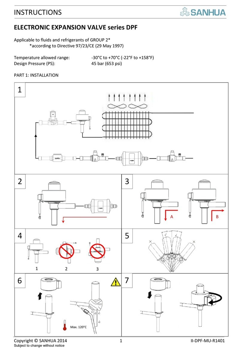
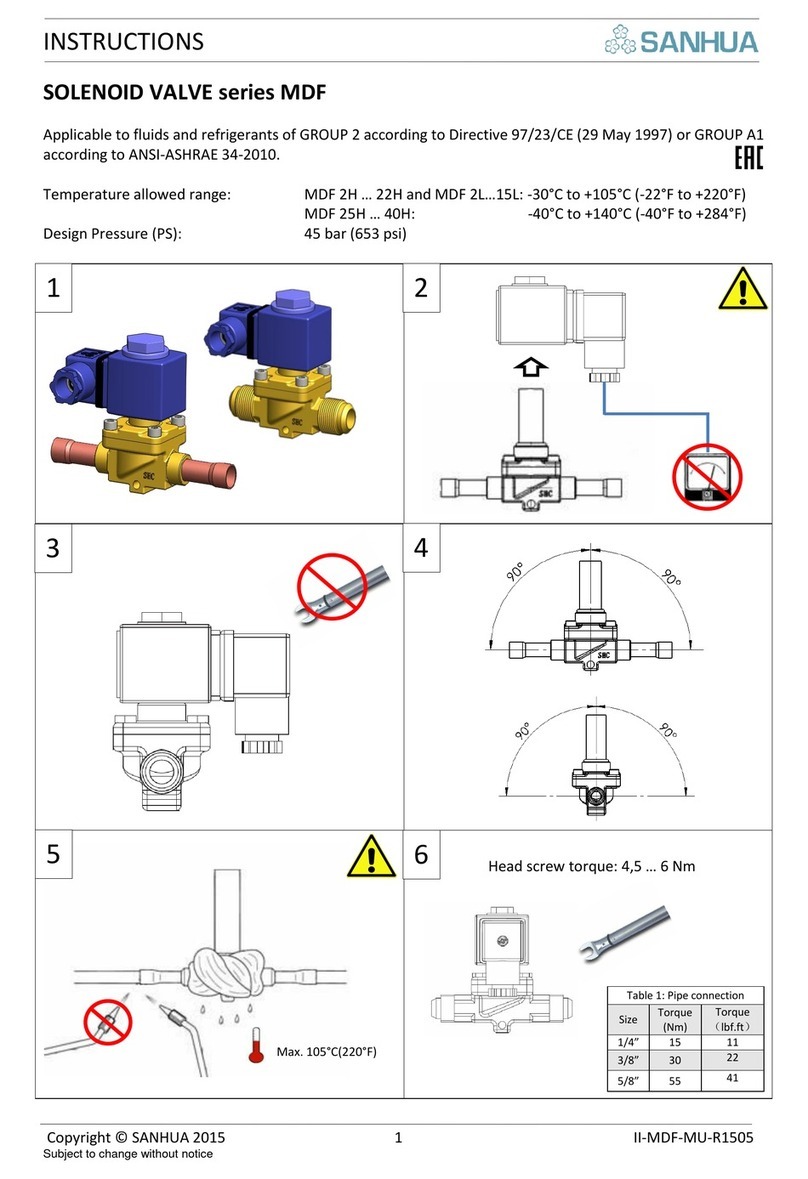
SOLENOID VALVE series MDF
Applicable to fluids and refrigerants of GROUP 2 according to Directive 2014/68/EU (15 May 2014) or GROUP
A1 according to ANSI-ASHRAE 34-2010. Solder version models with DN<25 mm and all MDF-A03-xxRH to
fluids of GROUP 1 according to Directive 2014/68/EU (15 May 2014) or GROUP A3/A2L according to ANSI-
ASHRAE 34-2010.
Product Range
Temperature allowed range (TS):
Design Pressure (PS):
MDF-A03(2H-22H,2L-15L)
-30°C to +105°C (-22°F to +220°F)
45 bar (653 psi)
MDF-B03(25H-40H)
-40°C to +140°C (-40°F to +284°F)
45 bar (653 psi)
MDF-A03(2RH-22RH)
-30°C to +105°C (-22°F to +220°F)
49 bar (710 psi)
MDF-A02(6H-22H,6L-15L)
-30°C to +105°C (-22°F to +220°F)
45 bar (653 psi)
Table 1: Pipe connection
Size
Torque
(Nm)
Torque
(lbf.ft)
1/4”
15
11
3/8”
30
22
5/8”
55
41
1
2
3
4
5
6
Max. 105°C(220°F)
4-5 Nm
5±0.5Nm
2.5±0.2Nm
N₂
N₂
INSTRUCTIONS
Copyright © SANHUA 2020 2 II-MDF-MU-R2010
Subject to change without notice
Model
MDF2-6
MDF10
MDF15
MDF20-22
Torque N*m
3±0.2
6±0.2
10±0.2
12±0.2
7
9
10
(0.2±0.05) Nm
8
(0.4±0.1) Nm
(0.6~0.7)
Nm
(0.5±0.1) Nm
(1±0.1) Nm
8a
aa
8b
aa
11
MDF-A03
MDF-A02
Gasket in right
side
Wire shell and rubber
ring are fully contacted
INSTRUCTIONS
Copyright © SANHUA 2020 3 II-MDF-MU-R2010
Subject to change without notice
ACTI
ON
English
Français
Deutsch
Italiano
Español
Русский
Chinese
1
MDF is available with
flare and solder
connections
Les électrovannes MDF
existent en connexion
flare (à visser) ou à
braser
Magnetventile der Serie
MDF sind mit Bördel-
oder Lötanschlüssen
erhältlich
Le valvole a solenoide
serie MDF possono
essere fornite con
attacchi filettati o a
saldare
La válvula solenoide
serie MDF se puede
suministrar con
conexiones para roscar
o soldar
Соленоидные
вентили MDF есть с
патрубками под
пайку или резьбу
MDF 系列电
磁阀可以螺
纹或焊接连
接
2
Remove the coil from
valve body before
installing valve to
system.
ATTENTION: Don’t
connect power
supply to the
electrical coil when it
is not mounted into
the valve
Retirer la bobine
électrique du corps de la
vanne avant d’installer
celle-ci dans le circuit
frigorifique.
ATTENTION: Ne pas
alimenter la bobine si
elle n’est pas connectée
à la vanne
Vor der Installation des
Ventils in den Kreislauf
die Spule vom
Ventilkörper abnehmen
ACHTUNG: An die Spule
keine Spannung
anlegen, solange diese
nicht fest auf den
Ventilkörper montiert
ist
Prima di connettere la
valvola nel circuito
frigorifero rimuovere la
bobina elettrica dal
corpo valvola
ATTENZIONE: Non
alimentare con tensione
la bobina elettrica
quando questa non è
montata sulla valvola
Quitar la bobina
eléctrica del cuerpo de
la válvula antes de
conectarla al circuito
de refrigeración
ATENCION: No
alimentar a la bobina
con tensión cuando no
está montada en la
válvula
Перед монтажом
вентиля снимите
катушку
ВНИМАНИЕ:
Не подключайте
катушку в сеть до
установки на
вентиль
将阀接入系
统管路前,
将线圈从阀
体上移除
注意:当线
圈没有装在
阀体上时不
要通电
3
Screw off manually
the bolt on the top of
the coil
Dévisser à la main la vis
sur le dessus de la
bobine
Die Schraube oberhalb
der Spule manuell
abschrauben
Svitare manualmente il
bullone posto sopra alla
bobina
Ajustar manualmente
el tornillo superior de
la bobina
Выкрутите вручную
болт в верхней
части катушки
手动拧开线
圈顶上的螺
栓
4
Installation
inclination of valve
body complies with
the angle rated in
diagram
L’inclinaison de la vanne
doit se conformer aux
angles maxi indiqué sur
le schéma.
Die Rechtwinkeligkeit
der Antriebsachse
gegenüber der Längs-
und der Querachse
überprüfen.
Controllare che l’asse
verticale dell’attuatore
sia in posizione
perpendicolare rispetto
agli assi di simmetria
longitudinale e
trasversale (vedi figura)
Comprobar que el eje
actuador vertical esté
en posición
perpendicular con
respecto a los ejes de
simetria longitudinal y
transversal
Убедитесь, что
наклон продольной
и вертикальной
осей не превышает
допустимого
наклона в
установленной
позиции
阀体安装倾
角允许范围
如图所示
5
SOLDER VERSION:
Braze the two valve
connections using
specific alloy (SilFos
15). Use a wet rag on
the valve and
nitrogen during the
brazing process
VERSION A BRASER:
Braser les 2 connexions
en utilisant un alliage
spécifique (SilFos 15).
Protéger à l’aide d’un
chiffon mouillé le corps
de la vanne durant le
brasage que vous devez
faire sous azote
LÖTVERSION:
Einlöten des Ventils
unter Verwendung
spezieller Legierung
(SilFos 15). Während
des Lötvorgangs das
Ventil mit nassem
Lappen umwickeln und
mit Stickstoff spülen
VERSIONE A SALDARE:
Brasare le due
connessioni della
valvola usando una lega
specifica (SilFos 15).
Usare uno straccio
bagnato sulla valvola e
azoto durante il
processo di brasatura
VERSION SOLDAR:
Soldar las dos
conexiones de la
válvula usando una
aleación específica
(SilFos 15). Poner un
paño húmedo sobre la
valvula, y utilizar
Nitrógeno, durante el
proceso de soldadura
ПАТРУБКИ ПОД
ПАЙКУ:
при пайке
пользуйтесь
припоем (SilFos15).
Защитите вентиль
от перегрева
мокрой ветошью,
пайку производите
в потоке азота
焊接类型:
用特殊合金
焊接阀的两
端接口(推
荐SilFos
15)焊接过
程用湿布和
氮气保护
6
THREAD VERSION:
Tighten the threaded
nut to the thread
connection
respecting the
torque values in the
table 1
VERSION A VISSER:
Serrer l’écrou en
respectant les couples
de serrage
recommandés dans la
table 1
BÖRDEL VERSION:
Überwurfmutter der
Verschraubung mit
Schlüssel unter
Beachtung des
Drehmoments in Tab.1
anziehen
VERSIONE AD AVVITARE
Serrare il dado di
serraggio alla
connessione filettata
rispettando i valori di
coppia riportati nella
tabella 1
VERSION ROSCAR:
Efectuar el roscado de
las conexiones
roscadas respetando
los valores de ajuste
que se indican en la
tabla 1
РЕЗЬБОВЫЕ
ПАТРУБКИ:
Затяните накидную
гайку, не превышая
допустимого
усилия (табл.1)
螺纹类型:
拧紧螺母到
螺纹接口注
意允许扭矩
值在表 1中
7
Remove the screw(s)
that fix the external
gland on the coil.
Insert into the gland
the power supply
cable
Retirer la vis qui fixe le
presse-étoupe de la
bobine. Insérez dans le
presse-étoupe le câble
d'alimentation
Befestigungsschraube
des Spulensteckers
entfernen. Das
Anschlusskabel in den
Spulenstecker einführen
Rimuovere la vite che
fissa il pressacavo sulla
parte esterna della
bobina. Inserire
attraverso il pressacavo
il cavo di alimentazione
Quitar el tornillo que
fija la caja terminal a la
bobina. Introducir el
cable de alimentación
a través de la caja
Отверните винт
коннектора.
Вставьте провод
питания в
коннектор
移出螺钉,
固定好外压
盖,将引线
插入压盖中
8
Do not install the
junction box with
lead wire outlet
upwards
Ne pas installer la boîte
de jonction avec la
sortie de câble vers le
haut
Installieren Sie den
Ausgang der
Anschlusskabel nicht
nach oben
Non installare il
connettore DIN con
l’usita del cavo verso
l’alto
Tirar de la parte
externa de la bobina
extrayéndola del
cuerpo pricipal
Не устанавливайте
коннектор выходом
вверх
接线盒引线
出口禁止朝
上
9
Wire the power
supply cable to the
coil with 3 terminals.
Raccorder la bobine
avec les 3 fils
électriques comme
indiqué sur le schéma
Das Kabel mit den 3
Anschlüssen der Spule
verbinden.
Connettere i cavi di
alimentazione alla
bobina usando i 3
morsetti in figura
Conectar el cable de
alimentación a los 3
terminales de la
bobina indicados en la
figura
Подключите
провода питания с
помощью 3 клемм
как показано на
рисунке
电源引线使
用3个接口
如图中所示
10
Utilize screwdriver to
remove 4 screws and
close the valve
A l’aide d’une clé 6
pans, vous pouvez
ouvrir et fermer le corps
de la vanne
Mit einem Torx
Schraubendreher die 4
Schrauben vom
Ventilkörper entfernen
Usando un cacciavite a
brugola rimuovere le 4
viti che chiudono il
corpo valvola
Con un destornillador
Allen quitar los 4
tornillos que cierran el
cuerpo de la válvula
Для вывинчивания
ввинчивания 4
винта корпуса
вентиля
используйте
отвертку
使用螺丝刀
将4个螺钉
移除并关闭
阀门
11
Assemble the valve
according to the
diagram and do not
dismantle the valve if
unnecessary.
NC (normally closed);
NO (normally open).
Assembler la vanne en
respectant l’ordre des
pièces internes comme
indiqué sur le schéma.
Mais ne la démontez
pas, si cela n’est pas
absolument nécessaire.
NC = Normalement
Fermé
NO = Normalement
Ouverte
Aufbau des
Magnetventils gemäß
Bild montieren.; Es ist
nicht empfohlen das MV
auseinander zu bauen.
NC (stromlos
geschlossen)
NO (stromlos geöffnet)
Assemblare la valvola a
solenoide rispettando la
struttura interna
mostrata in figura. NC
(normalmente chiusa);
NO (normalmente
aperta). E’ sconsigliato
smontare la valvola se
non per necessaria
manutenzione.
Ensamblar la válvula
solenoide respetando
la estructura interna
como indica la figura.
NC (normalmente
cerrada) N.O.
(normalmente abierta)
No se recomienda su
desmontaje en la
operación de
soldadura
Соберите вентиль
согласно рисунку
(NC - нормально
закрытый; NO -
нормально
открытый). Не
рекомендуется
изымать
внутренние части
装配电磁阀
注意内部结
构如图中所
示,NC(常
关). 但我
们不建议打
开电磁阀。

This manual suits for next models

15

Other Sanhua Control Unit manuals

Sanhua LPF Series User manual

Sanhua

Sanhua LPF Series User manual

Sanhua VPF Series User manual

Sanhua

Sanhua VPF Series User manual

Sanhua TXV Series Manual

Sanhua

Sanhua TXV Series Manual

Sanhua DPF Series User manual

Sanhua

Sanhua DPF Series User manual

Sanhua RFKA Series User manual

Sanhua

Sanhua RFKA Series User manual
Sanhua SBV Series User manual

Sanhua

Sanhua SBV Series User manual

Sanhua SBV Series User manual

Sanhua

Sanhua SBV Series User manual

Sanhua LPF Series User manual

Sanhua

Sanhua LPF Series User manual

Sanhua RFGD Series User manual

Sanhua

Sanhua RFGD Series User manual

Sanhua RFKA Series User manual

Sanhua

Sanhua RFKA Series User manual

Sanhua RFGB Series User manual

Sanhua

Sanhua RFGB Series User manual

Sanhua PS01 Series User manual

Sanhua

Sanhua PS01 Series User manual

Sanhua RFGB Series User manual

Sanhua

Sanhua RFGB Series User manual

Sanhua RFKA Series User manual

Sanhua

Sanhua RFKA Series User manual

Sanhua RFGD Series User manual

Sanhua

Sanhua RFGD Series User manual

Sanhua RFGB Series User manual

Sanhua

Sanhua RFGB Series User manual

Sanhua RFKH Series User manual

Sanhua

Sanhua RFKH Series User manual

Sanhua RFGD Series User manual

Sanhua

Sanhua RFGD Series User manual

Sanhua PEV0 User manual

Sanhua

Sanhua PEV0 User manual

Sanhua RFKH series User manual

Sanhua

Sanhua RFKH series User manual

Sanhua RFKH Series User manual

Sanhua

Sanhua RFKH Series User manual

Sanhua MDF Series User manual

Sanhua

Sanhua MDF Series User manual

Sanhua DPF-R Series User manual

Sanhua

Sanhua DPF-R Series User manual

Sanhua SBV Series User manual

Sanhua

Sanhua SBV Series User manual

Popular Control Unit manuals by other brands

ARTESYN EMBEDDED TECHNOLOGIES ATCA-736x SATA quick start guide

ARTESYN EMBEDDED TECHNOLOGIES

ARTESYN EMBEDDED TECHNOLOGIES ATCA-736x SATA quick start guide

Qcells Q.PEAK DUO M-G11 Series Installation and operation manual

Qcells

Qcells Q.PEAK DUO M-G11 Series Installation and operation manual

Alfalaval Unique PMO Plus Series instruction manual

Alfalaval

Alfalaval Unique PMO Plus Series instruction manual

Ublox TOBY-L1 series System integration manual

Ublox

Ublox TOBY-L1 series System integration manual

Hi-Spec RF-PRO instruction manual

Hi-Spec

Hi-Spec RF-PRO instruction manual

Krom Schroder VG 10/15 operating instructions

Krom Schroder

Krom Schroder VG 10/15 operating instructions

red lion Graphite GMJ1939 installation guide

red lion

red lion Graphite GMJ1939 installation guide

Oriental motor OPX-2A operating manual

Oriental motor

Oriental motor OPX-2A operating manual

Lightwave LW321 instruction manual

Lightwave

Lightwave LW321 instruction manual

Ublox MAX-8 Series Hardware Integration Manual

Ublox

Ublox MAX-8 Series Hardware Integration Manual

Ublox NEO-M8U Hardware Integration Manual

Ublox

Ublox NEO-M8U Hardware Integration Manual

Alfalaval Unique SSV PN10 instruction manual

Alfalaval

Alfalaval Unique SSV PN10 instruction manual

Alfalaval LKB Series instruction manual

Alfalaval

Alfalaval LKB Series instruction manual

KEBCO 00.F4.010-3009 instruction manual

KEBCO

KEBCO 00.F4.010-3009 instruction manual

Krom Schroder BCU 370 operating instructions

Krom Schroder

Krom Schroder BCU 370 operating instructions

SPX FLOW APV DELTA UF3(A) instruction manual

SPX FLOW

SPX FLOW APV DELTA UF3(A) instruction manual

GiBiDi BE24 Instructions for installation

GiBiDi

GiBiDi BE24 Instructions for installation

Ublox LEXI-R422 System integration manual

Ublox

Ublox LEXI-R422 System integration manual

manuals.online logo
manuals.online logoBrands
  • About & Mission
  • Contact us
  • Privacy Policy
  • Terms and Conditions

Copyright 2025 Manuals.Online. All Rights Reserved.