olympia electronics BS-464 User manual

DESCRIPTION
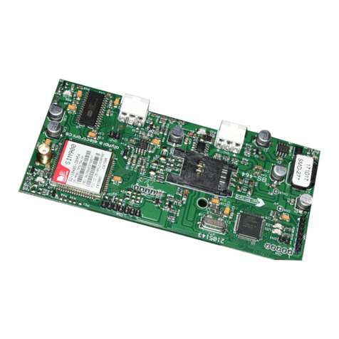
The BS-464 (figure1) is a module that can
be fitted only on the main board of the BS-
468 burg l a r a larm panel fr o m Olympia
Electronics. It can receive and send SMS
messages to and from selected telephone
numbers. These telephone numbers are
stored in the BS-468 panel’s memory and
do not erase in the event of a power failure
but can be changed by the user for as many
times as required. The BS-464 can also
accept commands from unknown telephone
numbers if the user requires.
INSTALLATION
The user must install the antenna (figure 4)
and the SIM card(figures 2 & 3) on the
board for it to become operational. Next,
the card is installed on the BS-468 panel
(figure 5) .
GENERAL INSTRUCTIONS
Verify that the GSM unit is placed in an area
were the signal is adequate. This can be
checked via the B S-4 66 keyboard. The
scale shows 0 to 4 bars. Signals lower that
2 bars can cause bad sound quality and
calls that cannot be sent and received. In
this case it is advised to test the system
using a SIM card from another provider.
Please note that if a call is not feasible due
to a low signal, when the signal is obtained
the GSM will sen d a ver b a l m e s s a g e
containing the alarm status during the time
of the unfeasible call. This is valid only if
this service is activated by the provider.
If the GSM unit is installed near a boarder
line then there might be increased charges
due to the roaming service. To avoid this,
deactivate the roaming service.
Some tele p h o n e u n i t s m i g h t exhibit
sensitivity due to being near the GSM unit. If
something like this is observed it is advised
to re orien t or to r e l o cate t h e affected
telephone device.
Each and every remote command to the
GSM unit must be accompanied with a valid
access code.
Warning!! It is not advised to use a high
gain or directional an t e n n a i n o r d e r to
improve the signal strength. Using such
ante n n a s wil l lead to uns t a b l e
communications because only one cellular
bas e will be used by th e GSM unit. Be
advised that GSM systems do not operate
correctly when the cellular base station is
more that 30km away beca u s e o f
communication delays. This is true even if
the signal is strong.
Warning!! The use of pre-paid SIM cards in
the GSM unit is not advised because some
providers block these card when they do not
have enough credit or when they are not get
credited often. If this is the case with your
provider then use tariffed SIM cards.
SIM CARD
It is suggested to install a SIM card, on
the BS-464, that will not require a PIN
number during the startup of the device.
To disable the PIN requirement, insert the
SIM card into a cell phone and disable the
PIN requirement. Next remove the SIM card
from the cell phone and insert it into the SIM
card holder of the BS-464.
WARNING: Never insert or remove a SIM
card from the BS-464 when the BS-464 is
powered. There is a chance that the SIM
card might be damaged. To insert/remove
TECHNICAL CHARACTERISTICS
ΟPΕΡΑΤΙΟΝ TEMPERATURE RANGE
RELATIVE HUMIDITY
EXTERNAL DIMENSIONS
WEIGHT
GUARANTEE
OPERATION VOLTAGE
CONSUMPTION
Powered by the BS-468 panel
0 to 60 C
o
Up to 95%
2 years
45gr.
101 x 61 x 25 mm
921464000_09_008
Page 1 from 5
BS-464 GSM TELEPHONE DIALER CARD FOR BS-468 PANELS
30mA (quiescent). 120mA (during a call)
PRODUCED IN ACCORDANCE WITH EN 50130-4, EN 55022, ETSI EN 301 489-7, ETSI EN 301 511, EN 60950-1, ETSI EN 301 419-1
Thank you for your trust in our products.
Olympia Electronics - European manufacturer.

921464000_09_008
closed without any other action. If the “#”
key is pressed then 2 beeps are heard, the
line is closed and the GSM dialer does not
dial any other numbers since one number
has already been informed. This is done to
prevent spending credit from the SIM card
and to preve n t d i s t u r b ing the other
numbers.
It is stressed that if the call is dismissed by
the user or the user does not pick up the
phone the call might still be answered by
the automatic telephone answering service,
if it is enabled by the service provider. In
this case the call will still be credited. For
this not to happen , the tele p h o n e
forward i n g to the tele p h o ne answerin g
service must be disabled. This is the main
reason why it is suggested to use SMS
instead of calling. Also the use of SMS is
more simple than using calls.
INCOMING CALLS
Regarding calls toward the GSM module it
is require to enter one of the 2 codes (user
or technician) in order to retrieve the status
of the syst e m . I f an action is re q u i r e d
(system arming) e.t.c) then an additional
code is also required. When a call is placed
to the GSM and the GSM module picks up
the line is will issue one beep. After the
beep is heard we must enter the user or
tech n i c i a n c o d e u s i n g our handset
keyboard. If the code is wrong then 3 beeps
are heard and the line is terminated. If the
code is cor rect then the syste m stat us
message is replayed 3 times. When the
messages finish a beep is heard and the
GSM waits for another code entry. Now we
can enter the user code, the technician
code or one of the 5 0 ge neral purpose
codes. If the code is wrong then 3 beeps
are heard and the line is terminated. If the
code is correct then the action(depending
on the code) is executed, 2 beeps are heard
and the new system status message will be
replayed 3 times after which the line will be
terminated.
INCOMING SMS
A command can also be sent by using SMS.
Each command must have a specific format
to be accepted by the GSM system. In any
case, the command must also contain a
valid code. SMS commands can be used to
do specific tasks (arming, disarming of the
system, activation/diactivation of specific
outputs of the BS-468 panel) or used to get
retrieve status information of the system.
For the above it is essential that the SMS
command also contains the main user code.
the SIM card we must either remove the
GSM module from the panel or we can
leave it on the panel and disconnect the
panel’s power supply and battery.
CAPABILITIES
It ha s pre-r e corded m essage s that a r e
stored in a memory area that cannot be
erased when the power is removed. These
messages are used to inform the user of the
present state of the system (alarm, fault,
arming or disarming).
It can be set to do calls or to send an SMS to
all events or to selected events (i.e alarm,
fault e.t.c) or in combination of events (i.e.
During an alarm and fault).
In order for someone to be able to send a
command to the GSM module via SMS or by
calling, the number must be stored in the
memory and remote access must be enable
for that nu m b e r. A l t e rnatel y yo u ca n
activate the selection so the unit will accept
commands from all the telephone numbers.
Please note that the tele pho ne number
must be stored without the country code in
the beginning. If the monitored area is in
another country then the number must be
stored including the country code in the
beginning. Finally the GSM will respond to
an incoming call after 15 seconds, if this
option is selected. If it is not selected then
the GSM will permit the line to ring for a few
seco n d s and then terminate that ca ll
without answering.
OUTGOING SMS
In case of an outgoing SMS, it will contain
the type of event, the sou r c e , t h e
description of the event and the date and
time of the event occurrence. For example
“FAULT, BATTERY, UNC O N N E C T E D
BATTERY, 07/05/12, 14:58.”.
OUTGOING CALLS
During an outgoing call, when the call is
answered first the welcome message is
reproduced, then there is a beep sound and
finally the message concerning the state of
the system is played for 3 times. If, for
example the system is disarmed and there
is a fault then the mess a g e “FAULT,
DIS A R M E D ” will be h e a r d for 4 t i m e s
whereas if there is an alarm and the system
is armed the message “ALARM, ARMED”
will be heard for 3 times. At the end of the
message a beep will be heard and after 5
seconds the line will be closed. If during the
message period any key apart from the “#”
key is pressed, on the receiving telephone,
then 3 bee ps are heard and the l ine is
Page 2 from 5
Also an SMS can be used to request the
status of the system. In this case just send
the code of the main user and nothing else.
Finally, the SMS can also contain one of the
50 general purpose codes. In this case no
other code is required. If the sent SMS is
valid then the GSM module send an SMS
with the status of the system to the phone
number that it received the command SMS
from. If no return SMS is received then this
mea n s t h e s e n t S M S w a s not valid .
Probable causes are wrong format, wrong
code or the phone number that sent the
comm a n d has not b e e n s e t to send
commands. A command can either contain
upper or lower case English characters.
Each s ms c o n t a ins o n l y o n e val i d
comm a n d . For a c o m m a n d to be
considered valid it must contain a space
between the keyword (codes, commands,
e.t. c ) . A va l i d comm a n d is a l w ays
acknowledged by a return sms containing
the current status of the system.
Below we can see the SMS commands.
Lets presume the main user code is 1234.
The format is always the same and consists
of t h e c o de, a s p a c e and t h e n the
command.
1234 ON ARM
1234 OFF DISARM
1234 SEND STATUS
1234 P1 ON ACTIVATE OUTPUT
1234 P1 OFF DEACTIVATE OUTPUT
1234 P2 ON ACTIVATE OUTPUT
1234 P2 OFF DEACTIVATE OUTPUT
1234 P3 ON ACTIVATE OUTPUT
1234 P3 OFF DEACTIVATE OUTPUT
1234 RELAY ON ACTIVATE OUTPUT
1234 RELAY OFF DEACTIVATE OUTPUT
REMAINING CREDITS ON PREPAID SIM
CARDS
We can verify the remaining credits of a
pre paid SIM card install ed in the GSM
module by using the CREDIT command(if
this service is enabled by the provider). The
format of this command depends on the
service provider of the SIM card. If for
example the service provider requires that
you send the word “CR” to the number 1314
so it can report the remaining credits that
the SIM card has and your master code is
1234, then the format of the commands is
the following:
921464000_09_008
1234 CREDIT CR#1314
Which means the first we send the master
code followed by the word “CREDIT”, then
the SMS content (CR), then the (#) and
finally the number of the service provider
(1314). If the master code and the format
are correc t th en the GSM will send the
message “CR” to the number 1314. When it
receives an answer by the service provider
it will report this to the cell phone that sent
the credit command. The word “CR” and the
number “1314” must be replaced by suitable
data obtained from your SIM card service
provider.
If an empty SMS is required , then after the
word CREDIT leave a space and the write
“#” and the provider number.
Please note that 5 minutes after the CREDIT
command has been sent the GSM module,
each SMS that does not contain any of the
commands in the list (ON, OFF..e.t.c) that
arrives to the GSM module will be forwarded
to the cell phone that issued the CREDIT
command.
SENDING CODES
We can also send any of the 50 general
purpose codes to the GSM module. If for
example the code 0101 is a panic alarm it
can be sent using the following 2 methods.
0101 CODE
0101 *
Using the word “CODE” or the symbol “*”
after the code has the same function. If the
code 0101 is used to arm the system then by
sen d i n g t h i s SMS th e s y s t e m will be
armed.
RECORDING WELCOME MESSAGE
When GSM is calling someone and before
the system status is reproduced, a welcome
message is heard. This could be changed
by the user via a call to the GSM. Someone
could record for example the address of the
ins t a l l e d a l a r m s y s t e m , i n o r d e r to
understand each time which alarm system
made the call.
After the call to the GSM, proper master
code entry and system status reproduction,
if *1*1 will be dialed, then a beep is issued
and the recording starts. The recording lasts
about seven seconds. After the recording is
finished a beep is issued and the recorded
mess a g e i s th e n r e p r oduce d . F i n a lly
another beep is issued and the line is
terminated.
The r ecord ed mes sage w ill re place t he
factory installed message.
Page 3 from 5

Page 4 from 5 921464000_09_008
Figure 2 : Insert the S IM card into the
SIM holder as shown .
Figure 3 : Slide and lo ck the SIM card holder
into place.
Figure 1 : Α BS-464 GSM mod ule without a SIM
card and antenna. Slide and lift the SIM holder.
Figure 4 : Antenna co nnection onto
BS-464 pcb.
Note!! The antenna is recommend ed to be
installed out of th e panel box for maximum
performance.
The antenna cable may follow the pa th of
the rest connected cables through the
respective holes of the panel’s bas e.
Figure 5 : Installi ng the BS-464 GSM module
on the BS-468 panel.
INSTALLING THE BS-464 GSM MODULE IN THE BS-468 PANEL
Connect the antenna.

Page 5 from 5 921464000_09_008
WARRANTY
Olympia Electronics guarantees the quality, condition and operation of the goods. The period of
warranty is specified in the official catalogue of Olympia Electronics and also in the technical leaflet,
which accompanies each product. This warranty ceases to exist if the buyer does not follow the
technical instructions included in official documents given by Olympia Electronics or if the buyer
modifies the goods provided or has any repairs or re-setting done by a third party, unless Olympia
Electronics has fully agreed to them in writing. Products that have been damaged can be returned to
the premises of our company for repair or replacement, as long as the warranty period is valid.
Olympia Electronics reserves the right to repair or to replace the returned goods and to or not charge
the buyer depending on the reason of defection. Olympia Electronics reserves the right to charge or
not the buyer the transportation cost.
HEAD OFFICE
72nd km. O.N.R. Thessaloniki-Katerini
P.C. 60300 P.O. Box 06 Eginio Pierias Greece
www.olympia-electronics.gr
Table of contents
Other olympia electronics Control Unit manuals

olympia electronics
olympia electronics GR-8600 Series Assembly instructions

olympia electronics
olympia electronics GR-578/L/18/ST/WP User manual

olympia electronics
olympia electronics i-OLEG LumiGate GR-7610/V2 User manual

olympia electronics
olympia electronics LumiGate GR-7610 i-OLEG User manual

olympia electronics
olympia electronics BS-464 User manual
Popular Control Unit manuals by other brands

Samson
Samson EB 01b Mounting and operating instructions

Roto
Roto E-Tec Drive Installation and operation instructions

Audioplex
Audioplex CSVC1550 installation manual

Epec
Epec 5050 Technical document

Asco
Asco 290 Series Installation and maintenance instructions

Feig Electronic
Feig Electronic ID ISC.M02.M8 installation manual