Sharpe D-5-55 Parts list manual
Instructions/Parts
D-5-55
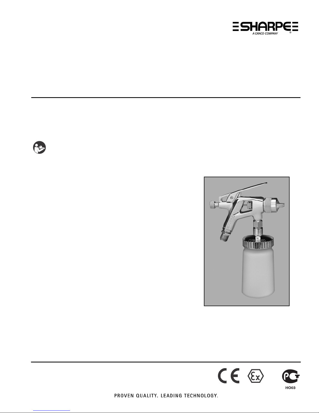
Siphon Feed Detail Spray Gun
For siphon feed spraying of automotive colors and clears. Ideal for touch-up and detail
work.
Maximum Air Inlet Pressure: 50 psi (345 kPa, 3.4 bar)
Part No. 7030 Spray Gun and 7510 Cup
Important Safety Instructions
Read all warnings and instructions in this
manual. Save these instructions.
309991E
ENG
II 2 G

2
WARNING
FIRE AND EXPLOSION HAZARD
Flammable fumes, such as solvent and paint fumes, in work area can ignite or explode. To help prevent
fire and explosion:
•Use equipment only in well ventilated area.
•Eliminate all ignition sources; such as pilot lights, cigarettes, portable electric lamps, and plastic drop
cloths (potential static arc).
•Keep work area free of debris, including solvent, rags and gasoline.
•Do not plug or unplug power cords, or turn power or light switches on or off when flammable fumes
are present.
•Ground all equipment in the work area. See Grounding instructions.
•Use only grounded hoses.
•Hold gun firmly to side of grounded pail when triggering into pail.
•If there is static sparking or you feel a shock, stop operation immediately. Do not use equipment
until you identify and correct the problem.
•Keep a working fire extinguisher in the work area.
EQUIPMENT MISUSE HAZARD
Misuse can cause death or serious injury.
•Do not operate the unit when fatigued or under the influence of drugs or alcohol.
•Do not exceed the maximum working pressure or temperature rating of the lowest rated system
component. See Technical Data in all equipment manuals.
•Use fluids and solvents that are compatible with equipment wetted parts. See Technical Data in all
equipment manuals. Read fluid and solvent manufacturer’s warnings. For complete information
about your material, request MSDS from distributor or retailer.
•Do not leave the work area while equipment is energized or under pressure. Turn off all equipment
and follow the Pressure Relief Procedure when equipment is not in use.
•Check equipment daily. Repair or replace worn or damaged parts immediately with genuine
manufacturer’s replacement parts only.
•Do not alter or modify equipment.
•Use equipment only for its intended purpose. Call your distributor for information.
•Route hoses and cables away from traffic areas, sharp edges, moving parts, and hot surfaces.
•Do not kink or over bend hoses or use hoses to pull equipment.
•Keep children and animals away from work area.
•Comply with all applicable safety regulations.
PRESSURIZED EQUIPMENT HAZARD
Fluid from the gun/dispense valve, leaks, or ruptured components can splash in the eyes or on skin and
cause serious injury.
•Follow the Pressure Relief Procedure when you stop spraying and before cleaning, checking, or
servicing equipment.
•Tighten all fluid connections before operating the equipment.
•Check hoses, tubes, and couplings daily. Replace worn or damaged parts immediately.
Setup
3
Setup
•Set shop air pressure regulator (not supplied)
according to paint manufacturer’s recommendation.
Do not exceed 50 psi (345 kPa, 3.4 bar).
•Make sure no air restrictions, such as low-volume
cheater-valves, obstruct the air flow. If an air adjust-
ing valve is desired, use a SHARPE Air Adjusting
Valve 24AAV (part no. 2210), 36AAV-HOV (part no.
3310) or HOV (part no. U04410).
•Install a shutoff valve (not supplied) downstream of
the air regulator to shut off gun air.
•Install an inline air filter (not supplied) to clean and
dry the air supply to the gun.
1. Turn off air supply.
2. Connect a clean, dry, filtered air supply to gun air
inlet (2).
3. If this is first time using the equipment, flush the
spray gun.
TOXIC FLUID OR FUMES HAZARD
Toxic fluids or fumes can cause serious injury or death if splashed in the eyes or on skin, inhaled, or
swallowed.
•Read MSDSs to know the specific hazards of the fluids you are using.
•Store hazardous fluid in approved containers, and dispose of it according to applicable guidelines.
PERSONAL PROTECTIVE EQUIPMENT
You must wear appropriate protective equipment when operating, servicing, or when in the operating
area of the equipment to help protect you from serious injury, including eye injury, hearing loss,
inhalation of toxic fumes, and burns. This equipment includes but is not limited to:
•Protective eyewear, and hearing protection.
•Respirators, protective clothing, and gloves as recommended by the fluid and solvent manufacturer.
WARNING
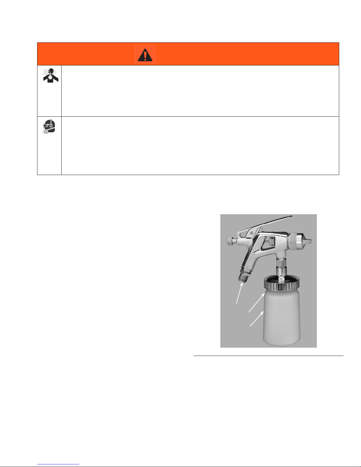
FIG. 1
2
A
101

Operation
4
Operation
Pressure Relief Procedure
1. Turn off gun air supply.
2. Trigger the gun to relieve pressure.
Flushing
Flush before using the equipment, before changing
colors, and when you are done spraying. Use solvent
that is compatible with gun wetted parts and fluid that
will be sprayed. Flush at lowest possible pressure.
NOTE: Refer to Compliant Cleaning Methods, page 5,
to comply with air quality laws if applicable.
1. Follow Pressure Relief Procedure.
2. Dispose of any paint in cup.
3. Fill cup with small amount of solvent.
4. Spray into grounded metal waste container until
equipment is clean.
5. Follow Pressure Relief Procedure.
Spraying
1. Fill cup (101) with material. Do not fill past cup
“shoulder” (A). See FIG. 1.
2. Screw cup (101) onto lid securely.
3. Slowly adjust gun air pressure while fully triggering
the gun until you have the desired atomization.
4. Adjust the pattern size and shape with the spray
width adjustment knob (10). See FIG. 2. Turn knob
clockwise to reduce pattern size and counterclock-
wise to increase it.
NOTE: See Troubleshooting guide if you experience
an irregular pattern.
5. Fluid control knob (7) is factory set for maximum
needle trigger travel and material flow. To decrease
needle/trigger travel and decrease fluid flow, turn
knob clockwise.
Follow Pressure Relief Procedure when you stop
spraying and before cleaning, checking, or servicing
equipment. Read warnings, page 2.
NOTICE
Excessive atomizing air pressure can increase
over-spray, reduce transfer efficiency, and result in a
poor quality finish from dry spray.
FIG. 2
7
10
Cleaning and Maintenance
5
Cleaning and Maintenance
NOTE: Clean air line filters as directed by the manufac-
turer.
Volatile Organic Compounds
(VOC) Regulation
In certain states, spraying solvents that release VOC’s
into the atmosphere when cleaning a spray gun is
prohibited. To comply with these air quality laws you
must use a cleaning method that prevents the escape of
VOC vapors into the atmosphere. See Compliant
Cleaning Methods below.
Compliant Cleaning Methods
•Place spray gun in a gun washer that completely
encloses the gun and components during cleaning,
rinsing, and draining.
•Spray solvent through the spray gun into a closed
gun cleaning station.
Cleaning Gun and Cup
NOTE: Refer to Compliant Cleaning Methods to
comply with air quality laws if applicable.
1. Follow Flushing procedure, page 4.
2. Use a rag moistened in solvent to wipe cup lid
(109), fluid tube (103), inside of cup (101), and out-
side of gun.
3. Blow dry gun inside and out. Lubricate gun as
described in Spray Gun Maintenance.
Cleaning Nozzle and Air Cap
To clean the air cap and nozzle, remove and
soak them in a compatible cleaning solution.
Clean them and front of gun with a
soft-bristle brush dipped into compatible
solvent. Do not use a wire brush or metal
tools. To clean out air cap holes, use a soft
implement, such as a toothpick.
Spray Gun Maintenance
•Frequently lubricate the gun moving parts with a
drop of non-silicone oil (part no. 8255).
•Do not disassemble the spray gun if you are having
a spray pattern problem. Check Troubleshooting,
page 6, for information on how to correct the prob-
lem.
•Check for fluid leakage. Tighten fittings or replace
equipment as needed.
NOTICE
•Do not submerge gun in solvent. Solvent dissolves
lubricant, dries out packings, and may clog air pas-
sages.
•Do not use metal tools to clean air cap holes as this
may scratch them and distort the spray pattern.
•Use a compatible solvent.
•Gun and cup can be cleaned in a gun washer.
NOTICE
•Trigger gun whenever you tighten or remove nozzle
to avoid damaging needle seat and nozzle.
•Do not use metal tools to clean air cap holes as this
may scratch them and distort the spray pattern.
Table of contents
Other Sharpe Paint Sprayer manuals


