Sharpe Cobalt 5812L User manual

SHARPE MANUFACTURING COMPANY • P.O. BOX 1441, MINNEAPOLIS, MN 55440-1441
1-800-742-7731, www.sharpe1.com
309999F, 4/2006
THE SPRAY GUN PEOPLE
FOR PRODUCT INFORMATION CALL:
1-800-742-7731
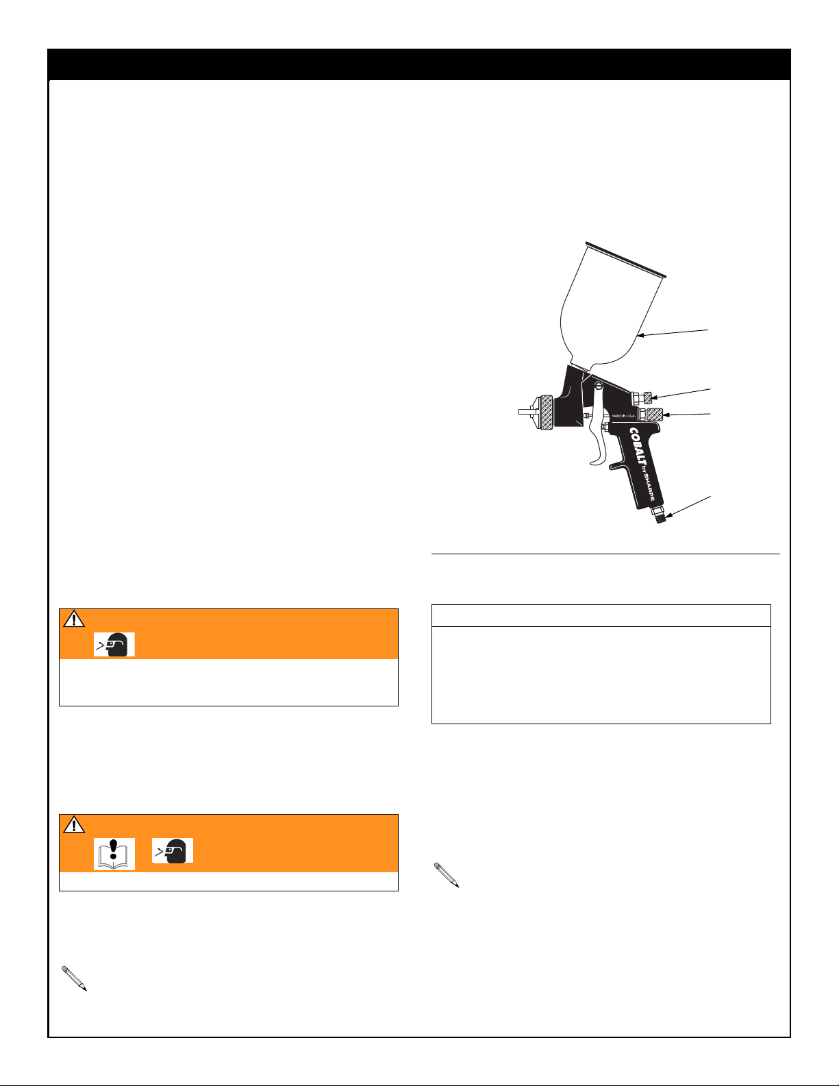
Cobalt
HVLP Gravity Feed Spray Gun
Compliant Gravity Feed Spray Gun
Maximum Air Inlet Pressure: 100 psi (0.7 MPa, 7 bar)
Maximum HVLP Compliant Air Pressure: see table below
Includes Cobalt Gravity Feed HVLP or Compliant Spray Gun and 650GC
Aluminum Gravity Cup
* At HVLP compliant air pressure
† At 50 psi (345 kPa, 3.4 bar) air inlet pressure
Important Safety Instructions
Read all warnings and instructions in this manual.
Save these instructions.
Gun Part
No.
Needle/Nozzle
Size (mm)
Air
Consumption
(CFM)
Maximum HVLP
Air Pressure
psi (kPa, bar) Recommended Usage
HVLP Gravity Feed Gun
5812L 1.2 13.9* 50 (345, 3.4) Topcoat, high solids, colors and clears
5814L 1.4 13.9* 50 (345, 3.4) Topcoat, high solids, colors and clears
5816L 1.6 13.9* 50 (345, 3.4) Topcoat, medium solids, colors and clears
5815L 1.5 12.5* 40 (276, 2.8) Primer, high solids, sealers
5818L 1.8 12.5* 40 (276, 2.8) Primer, general purpose
5823L 2.3 12.5* 30 (207, 2.1) Primer, high viscosity
Compliant Gravity Feed Gun
5712 1.2 13.8† Topcoat, high solids, colors and clears
5714 1.4 13.8† Topcoat, high solids, colors and clears
5716 1.6 13.8† Topcoat, medium solids, colors and clears
II 2 G

2 309999F
2 Year Limited Warranty
Sharpe warrants this product to the original user against defective material or workmanship for a period of 1 year from the date of
purchase.
Sharpe reserves the right to determine whether the part or parts failed because of defective material, workmanship, or other causes.
Failures caused by accident, alteration, or misuse are not covered by this warranty.
Sharpe, at its discretion, will repair or replace products covered under this warranty free of charge. Repairs or replacements of products
covered under this warranty are warranted for the remainder of the original warranty period.
Sharpe or its authorized service representatives must perform all warranty repairs. Any repair to the product by unauthorized service
representatives voids this warranty. The rights under this warranty are limited to the original user and may not be transferred to
subsequent owners.
This warranty is in lieu of all other warranties, expressed or implied, including warranties of merchantability and fitness for a particular
purpose. Some states do not allow the exclusion or limitations of incidental or consequential damages, so the above limitations may not
apply to you.
WARNING
FIRE AND EXPLOSION HAZARD
Flammable fumes, such as solvent and paint fumes, in work area can ignite or explode. To help prevent fire and explosion:
•Use equipment only in well ventilated area.
•Eliminate all ignition sources; such as pilot lights, cigarettes, portable electric lamps, and plastic drop cloths (potential
static arc).
•Keep work area free of debris, including solvent, rags and gasoline.
•Do not plug or unplug power cords or turn lights on or off when flammable fumes are present.
•Ground equipment and conductive objects in work area.
•If there is static sparking or you feel a shock, stop operation immediately. Do not use equipment until you identify and
correct the problem.
EQUIPMENT MISUSE HAZARD
Misuse can cause death or serious injury.
•Do not exceed the maximum working pressure or temperature rating of the lowest rated system component. See Tech-
nical Data in all equipment manuals.
•Use fluids and solvents that are compatible with equipment wetted parts. See Technical Data in all equipment manuals.
Read fluid and solvent manufacturer’s warnings.
•Check equipment daily. Repair or replace worn or damaged parts immediately.
•Do not alter or modify equipment.
•Use equipment only for its intended purpose. Call your Graco distributor for information.
•Route hoses and cables away from traffic areas, sharp edges, moving parts, and hot surfaces.
•Do not use hoses to pull equipment.
•Keep children and animals away from work area.
•Comply with all applicable safety regulations.
TOXIC FLUID OR FUMES HAZARD
Toxic fluids or fumes can cause serious injury or death if splashed in the eyes or on skin, inhaled, or swallowed.
•Read MSDS’s to know the specific hazards of the fluids you are using.
•Store hazardous fluid in approved containers, and dispose of it according to applicable guidelines.
PERSONAL PROTECTIVE EQUIPMENT
You must wear appropriate protective equipment when operating, servicing, or when in the operating area of the equipment
to help protect you from serious injury, including eye injury, inhalation of toxic fumes, burns, and hearing loss. This equip-
ment includes but is not limited to:
•Protective eyewear
•Clothing and respirator as recommended by the fluid and solvent manufacturer
•Gloves
•Hearing protection
PRESSURIZED EQUIPMENT HAZARD
Fluid from the gun/dispense valve, leaks, or ruptured components can splash in the eyes or on skin and cause serious
injury.
•Follow Pressure Relief Procedure in this manual, when you stop spraying and before cleaning, checking, or servicing
equipment.
•Tighten all fluid connections before operating the equipment.
•Check hoses, tubes, and couplings daily. Replace worn or damaged parts immediately.
3 309999F
COBALT GRAVITY FEED SPRAY GUN
Setup
•Check that your shop air provides adequate air flow.
•Use a minimum 3/8 in. ID air supply hose.
•Set shop air pressure regulator (not supplied) according to
paint manufacturer’s recommendation. See maximum pres-
sures and compliant air pressures on cover.
•Make sure no air restrictions, such as low-volume cheater-
valves, obstruct the air flow. If an air adjusting valve is
desired, use a SHARPE Air Adjusting Valve 24AAV (part
no. 2210), 36AAV-HOV (part no. 3310) or HOV (part no.
U04410).
•Install a shutoff valve (not supplied) downstream of the air
regulator to shut off gun air.
•Install an inline air filter (not supplied) to clean and dry the
air supply to the gun.
1. Make sure air supply is turned off.
2. Connect a clean, dry, filtered air supply to the gun air inlet
(9).
3. If this is first time using the equipment, flush the spray gun.
Operation
Pressure Relief Procedure
1. Turn off gun air supply.
2. Trigger the gun to relieve pressure.
Flushing
Flush before using the equipment, before changing colors, and
when you are done spraying. Use solvent that is compatible with
gun wetted parts and fluid that will be sprayed. Flush at lowest
possible pressure.
1. Follow Pressure Relief Procedure.
2. Dispose of any paint in cup.
3. Fill cup with small amount of solvent.
4. Spray into grounded metal waste container until equipment
is clean.
5. Follow Pressure Relief Procedure.
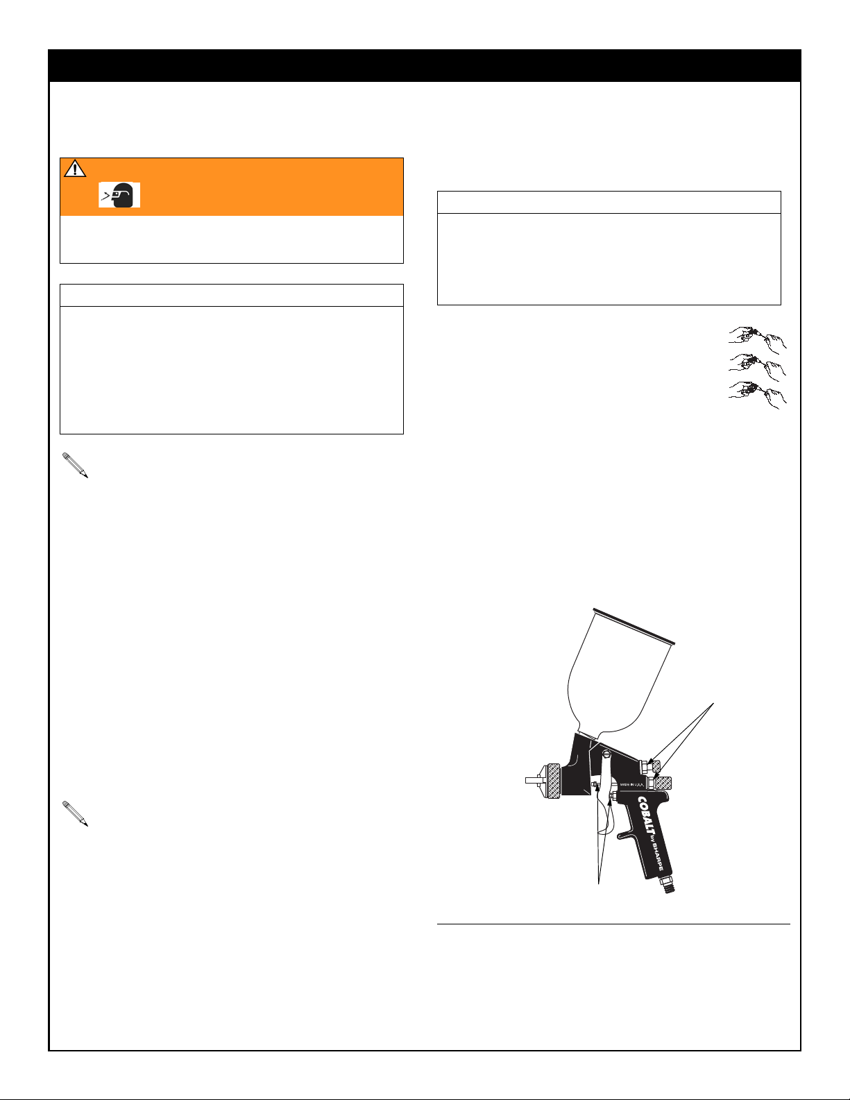
Spraying
1. Fill cup (20) with material. Do not fill past full markings on
cup.
2. Turn on shop air to gun and set atomizing pressure with the
gun fully triggered.
3. Adjust the pattern size and shape with the spray width
adjustment knob (16c). Turn knob clockwise to reduce pat-
tern size and counterclockwise to increase it.
4. Fluid control knob (15) is factory set for maximum needle
trigger travel and material flow. To decrease needle/trigger
travel and decrease fluid flow, turn the knob clockwise.
WARNING
Follow Pressure Relief Procedure when you stop spraying
and before cleaning, checking, or servicing equipment. Read
warnings, page 2.
WARNING
Read warnings, page 2.
Refer to Compliant Cleaning Methods, page 4, to com-
ply with air quality laws if applicable.
FIG. 1
CAUTION
Excessive atomizing air pressure can increase over-spray,
reduce transfer efficiency, result in a poor quality finish
from dry spray.
Regulatory agencies in certain states prohibit the operation
of a spray gun above 10 psi (69 kPa, .7 bar) atomizing air
cap pressure.
See Troubleshooting guide if you experience an irregular
pattern.
(6,0
9
20
16c
15
4 309999F
COBALT GRAVITY FEED SPRAY GUN
Cleaning and Maintenance
Volatile Organic Compounds (VOC)
Regulation
In certain states, spraying solvents that release VOC’s into the
atmosphere when cleaning a spray gun is prohibited. To comply
with these air quality laws you must use a cleaning method that
prevents the escape of VOC vapors into the atmosphere. See
Compliant Cleaning Methods below.
Compliant Cleaning Methods
•Place spray gun in a gun washer that completely encloses
the gun and components during cleaning, rinsing, and
draining.
•Spray solvent through the spray gun into a closed gun
cleaning station.
Cleaning Gun and Cup
1. Follow Flushing procedure, page 3.
2. Use a rag moistened in solvent to wipe outside of gun and
cup.
3. Make sure cup lid vent hole is clear.
4. Blow dry gun inside and out. Lubricate gun as described in
Spray Gun Maintenance.
Cleaning Nozzle and Air Cap
To clean the air cap and nozzle, remove and soak
them in a compatible cleaning solution. Clean them
and front of gun with a soft-bristle brush dipped
into compatible solvent. Do not use a wire brush or
metal tools. To clean out air cap holes, use a soft
implement, such as a toothpick.
Spray Gun Maintenance
•Frequently lubricate the gun moving parts with a drop of
non-silicone oil (part no. 8255). See FIG. 2.
•Do not disassemble the spray gun if you are having a spray
pattern problem. Check Troubleshooting, page 5, for infor-
mation on how to correct the problem.
•Check for fluid leakage. Tighten fittings or replace equip-
ment as needed.
WARNING
Follow Pressure Relief Procedure when you stop spraying
and before cleaning, checking, or servicing equipment. Read
warnings, page 2.
CAUTION
•Do not submerge gun in solvent. Solvent dissolves lubri-
cant, dries out packings, and may clog air passages.
•Do not use metal tools to clean air cap holes as this may
scratch them and distort the spray pattern.
•Use a compatible solvent.
•Gun and cup can be cleaned in a gun washer.
Clean air line filters as directed by the manufacturer.
Refer to Compliant Cleaning Methods to comply with air
quality laws if applicable.
CAUTION
•Trigger gun and use nozzle removal tool 41160 when-
ever you tighten or remove nozzle to avoid damaging
needle seat and nozzle.
•Do not use metal tools to clean air cap holes as this may
scratch them and distort the spray pattern.
FIG. 2
(6,0
Lube
Lube
5 309999F
COBALT GRAVITY FEED SPRAY GUN
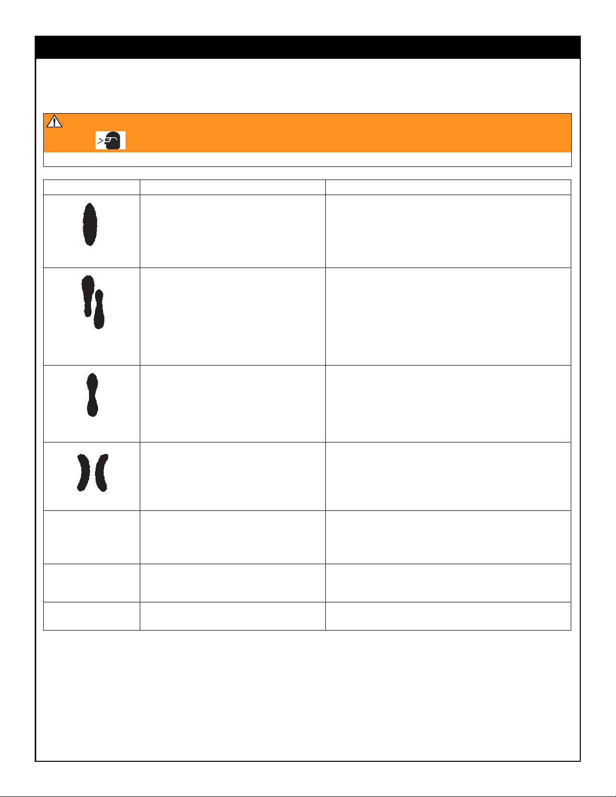
Troubleshooting
WARNING
Follow Pressure Relief Procedure, page 3, before troubleshooting or servicing. Read warnings, page 2.
Problem Cause Solution
Normal pattern No action necessary
Dirty or damaged air cap or fluid nozzle. Rotate air cap 180°.
If pattern follows air cap, problem is in air cap. Clean and
inspect. See page 4. If pattern is not corrected, replace air
cap.
If pattern does not follow the air cap, the problem is with the
fluid nozzle. Clean and inspect the nozzle. See page 4. If the
pattern is not corrected, replace nozzle.
Pressure too high for viscosity of material
being sprayed.
a. Reduce air pressure.
b. Increase material viscosity
c. Correct pattern by narrowing fan size with spray width
adjustment knob.
Dirty or distorted air horn holes. Rotate air cap 180°.
If pattern follows air cap, problem is in air cap. Clean and
inspect. See page 4. If pattern is not corrected, replace air
cap.
Gun spitting Air getting into paint stream •Check if cup is empty and fill.
•Tighten fluid nozzle.
•Check and tighten fluid needle packing nut.
•Check fluid nozzle seat for damage.
Will not spray. a. Cup is empty a. Fill cup.
b. Fluid adjustment knob (15) turned too far
clockwise.
b. Adjust knob (15) to the counterclockwise.
Excessive air blowing
back
a. Loose fluid nozzle. a. Tighten fluid nozzle.
b. Damaged fluid nozzle seat. b. Replace seat.
Right
Wrong
Heavy top or
bottom pattern
Wrong
Split pattern
Wrong

6 309999F
COBALT GRAVITY FEED SPRAY GUN
Parts
19
REF 12
12 32* 33
34
14* 18
7*
4* 10
13* 15
2a* 2d* 2c 2b* 2e* 2f*
2
89
1
3*
16a* 16b* 16c
17
16
11
35
36
6
20e
20b
20c
20a
20
20d

7 309999F
COBALT GRAVITY FEED SPRAY GUN
Gun Accessory Tools
Part No. 41160: 1/2 in. Nozzle Removal Tool
Part No. 41150: Nozzle Cleaning Brush
Technical Data
Maximum Air Inlet Pressure: 100 psi (0.7 MPa, 7 bar)
Maximum HVLP Compliant Air Pressure: see front cover
(delivers 10 psi (69 kPa, 0.7 bar) spraying pressure at air cap)
Air Consumption: see table on cover
Air Inlet: 1/4 (R1/4-19) npsm
Weight: 1 lb. 8 oz. (0.68 kg)
Gravity Cup Size: 22 oz. (650 cc) cup
Wetted Parts: stainless steel, carbon steel, aluminum, brass,
low density polyethylene
Gun
Part
No.
Needle/
Nozzle
Size (mm)
Air Cap
Part No.
Needle/Nozzle
Set Part No.
HVLP Gravity Feed Gun
5812L 1.2 28012 118534
5814L 1.4 28012 118536
5815L 1.5 28015 118649
5816L 1.6 28012 118535
5818L 1.8 28015 118537
5823L 2.3 28015 118650
Compliant Gravity Feed Gun
5712 1.2 28018 118534
5714 1.4 28018 118536
5716 1.6 28018 118535
Ref.
No. Part No. Description Qty.
1 28127 Gun Handle, HVLP only 1
28128 Gun Handle, Compliant only 1
2 26016 Air Valve Assembly;
Includes items 2a-2f
1
2a* 26032 •Packing Nut 1
2b* 25066 •Air Valve 1
2c 16151 •Housing 1
2d* 16162 •Packing
2e* 16167 •Air Valve Spring 1
2f* 16163 •Gasket 1
3* 10333 Trigger Screw 1
4* 16163 Gasket 1
6 26042 Trigger 1
7* 26044 Trigger Shaft 1
8 26054 Pipe Plug 1
9 9993 Air Inlet Fitting 1
10 26056 Width Control Valve 1
11 118524 Pressure Limit Bushing; HVLP Guns
only
1
12 see table Needle/Nozzle Set 1
13* 16150 Needle Spring 1
14* 10326 Gasket 1
15 25092 Fluid Control Knob 1
16 26018 Width Control Assembly;
Includes item 16a-16c
1
16a* 16175 •Retaining Ring 1
16b 38120 •O-Ring 1
16c 26066 •Body 1
17 26065 Control Valve/Knob 1
18 41137 Screw, 7/16-27 UNS
19 see table Air Cap 1
20 6685 Gravity Cup;
Includes items 20a-20e
1
20a 22002 •Lid Assembly; Includes items 20b-20c 1
20b 22001 -Lid Only 1
20c 22178 -“No Drip” Assembly 1
20d 22107 •Gasket 1
20e 21719 •Filter 1
32 16100 Nozzle Gasket 1
33 118643 Gun Head 1
34 34941 Seal 1
35* 26022 Fluid Needle Packing 1
36 26032 Packing Nut 1
* Parts included in Repair Kit 28140
Ref.
No. Part No. Description Qty.
SHARPE MANUFACTURING COMPANY • P.O. BOX 1441, MINNEAPOLIS, MN 55440-1441
1-800-742-7731, www.sharpe1.com
309999F, 4/2006
COBALT GRAVITY FEED SPRAY GUN
Ref. Letter Description Model No.
ASharpe 606 U06710
Sharpe 606A U06720
Sharpe 606B 6730
Sharpe 880A 6950
Sharpe F88 8130
B707C 6930
707F 6920
707FC 6910
CDryaire Membrane 6770
DDryaire Desiccant 6760
ERefrigerated Air Dryer
25CFM 6880
35CFM 6885
50CFM 6890
75CFM 6895
3!452!
4%$
./2-!
$%3)##!.4
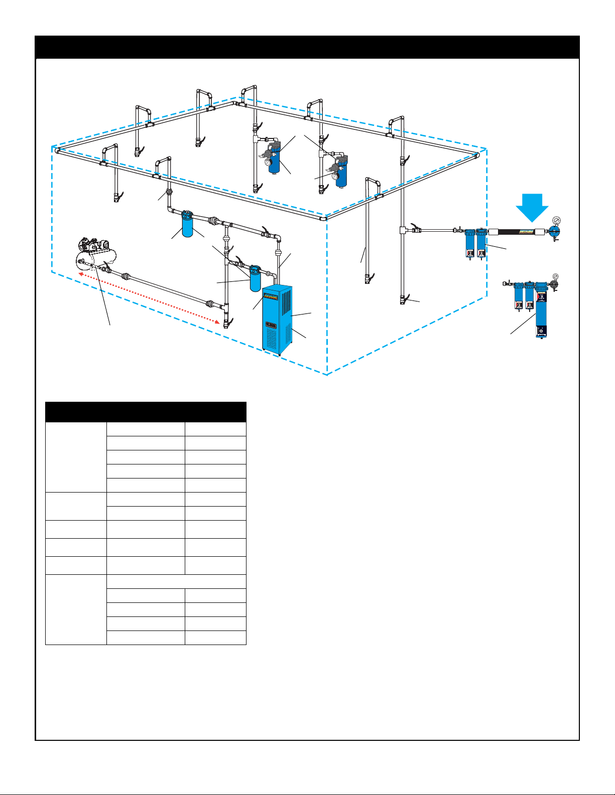
Air Control Unit
or Air Filter
Refrigerated
Air Dryer
Dryaire Membrane
or Desiccant Air
Drying Systems at
Paint Booth
Compressor
Model 707C
Oil Coalescer
Model 707F
Air Filter
Drain Leg
Ball Valve
Union
Air In
Air Out
Flexible Hose Between com-
pressor and Main Air Line
15ft.to20ft.
Main Air Line 1 in.
Pipe Minimum
A
C
D
E
B
This manual suits for next models
8
Table of contents
Other Sharpe Paint Sprayer manuals


