Shel lab SMI2-2 User manual

SMI INCUBATORS 220 – 240 Voltage
Installation - Operation Manual
SMI2-2 SMI6-2 SMI7-2 SMI11-2 SMI12-2

2 | Page
Pictured on cover: SMI6-2
SMI2-2
SMI7-2
SMI11-2
SMI12-2 (2 Stacked SMI6-2s)

3 | Page
SMI General Purpose Incubators 220 – 240 Voltage
Installation and Operation Manual
Part number: 4861572-2
Revised: November 7, 2017
SHEL LAB is a brand of Sheldon Manufacturing, INC.
Safety Certifications
These units are CUE listed by TÜV SÜD as incubators for professional, industrial, or educational use
where the preparation or testing of materials is done at an ambient air pressure range of 22.14 – 31.3
inHg (75 – 106 kPa) and no flammable, volatile, or combustible materials are being heated.
These units have been tested to the following requirements:
CAN/CSA C22.2 No. 61010-1:2012
CAN/CSA C22.2 No. 61010-2-010 + R:2009
UL 61010A-2-010:2002
UL 61010-1:2012
EN 61010-1:2010
EN 61010-2-010:2003

4 | Page
TABLE OF CONTENTS
INTRODUCTION ........................................................................................................................................................ 5
Read this Manual....................................................................................................................................................................5
Safety Considerations and Requirements ......................................................................................................................5
Contacting Assistance ..........................................................................................................................................................6
Temperature Reference Sensor Device ..........................................................................................................................6
Engineering Improvements..................................................................................................................................................6
RECEIVING YOUR INCUBATOR ..............................................................................................................................7
Inspect the Shipment............................................................................................................................................................. 7
Recording Data Plate Information.....................................................................................................................................8
INSTALLATION .......................................................................................................................................................... 9
Installation Procedure Checklist ........................................................................................................................................9
Required Ambient Conditions........................................................................................................................................... 10
Required Clearances........................................................................................................................................................... 10
Environmental Disruption Sources .................................................................................................................................. 10
Power Source Requirements ............................................................................................................................................. 11
Lifting and Handling ............................................................................................................................................................ 12
Leveling................................................................................................................................................................................... 12
Install Incubator in Location .............................................................................................................................................. 12
Installation Cleaning............................................................................................................................................................ 12
Deionized and Distilled Water.......................................................................................................................................... 13
Install the Shelving............................................................................................................................................................... 13
Access Port ............................................................................................................................................................................ 13
GRAPHIC SYMBOLS ................................................................................................................................................15
CONTROL PANEL OVERVIEW ............................................................................................................................... 17
OPERATION...............................................................................................................................................................19
Theory of Operation ............................................................................................................................................................ 19
Put the Incubator into Operation .................................................................................................................................... 20
Set the Incubator Temperature Set Point...................................................................................................................... 21
Set the Over Temperature Limit...................................................................................................................................... 22
Loading Samples................................................................................................................................................................. 23
Chamber Accessory Power Outlet ................................................................................................................................. 23
Humidifying the Incubator................................................................................................................................................. 23
Condensation and the Dew Point .................................................................................................................................. 24
USER MAINTENANCE............................................................................................................................................. 25
Cleaning and Disinfecting................................................................................................................................................. 25
Minimizing Contamination Exposure ............................................................................................................................. 26
Storing the Incubator...........................................................................................................................................................27
Door Components................................................................................................................................................................27
Electrical Components........................................................................................................................................................27
Calibrate the Temperature display ................................................................................................................................ 28
UNIT SPECIFICATIONS .......................................................................................................................................... 33
Weight..................................................................................................................................................................................... 33
Dimensions............................................................................................................................................................................ 33
Capacity ................................................................................................................................................................................. 34
Temperature ......................................................................................................................................................................... 34
Power...................................................................................................................................................................................... 34
PARTS LIST............................................................................................................................................................... 35
Ordering Parts and Consumables.................................................................................................................................. 35

5 | Page
INTRODUCTION
Thank you for purchasing a SHEL LAB Incubator. We know you have many choices in today’s competitive
marketplace when it comes to constant temperature equipment. We appreciate you choosing ours. We
stand behind our products and will be here for you if you need us.
READ THIS MANUAL
Failure to follow the guidelines and instructions in this user manual may create a protection
impairment by disabling or interfering with the unit safety features. This can result in injury or death.
Before using the unit, read the manual in its entirety to understand how to install, operate, and
maintain the unit in a safe manner. Keep this manual available for use by all operators. Ensure all
operators are given appropriate training before the unit begins service.
SAFETY CONSIDERATIONS AND REQUIREMENTS
Follow basic safety precautions, including all national laws, regulations, and local ordinances in your
area regarding the use of this unit. If you have any questions about local requirements, please
contact the appropriate agencies.
SOPs
Because of the range of potential applications, this unit can be used for, the operator or their
supervisors must draw up a site-specific standard operating procedure (SOP) covering each
application and associated safety guidelines. This SOP must be written and available to all operators
in a language they understand.
Intended Applications and Locations
The incubators are intended for constant temperature, non-humidified general incubation
applications in professional, industrial, and educational environments. The units are not intended for
use at hazardous or household locations.
Power
Your unit and its recommended accessories are designed and tested to meet strict safety
requirements.
•The unit is designed to connect to a power source using the specific power cord type
shipped with the unit.
•Always plug the unit power cord into a protective earth grounded electrical outlet
conforming to national and local electrical codes. If the unit is not grounded properly, parts
such as knobs and controls can conduct electricity and cause serious injury.
•Do not bend the power cord excessively, step on it, or place heavy objects on it.
•A damaged cord can be a shock or fire hazard. Never use a power cord if it is damaged or
altered in any way.
•Use only approved accessories. Do not modify system components. Any alterations or
modifications to your unit can be dangerous and void your warranty.

6 | Page
INTRODUCTION
CONTACTING ASSISTANCE
Phone hours for Sheldon Technical Support are 6 am – 4:30 pm Pacific Coast Time (west coast of
the United States, UTC -8). Please have the following information ready when calling or emailing
Technical Support: the model number and the serial number (see page 8).
EMAIL: [email protected]
PHONE: 1-800-322-4897 extension 4, or (503) 640-3000
FAX: (503) 640-1366
Sheldon Manufacturing, INC.
P.O. Box 627
Cornelius, OR 97113
TEMPERATURE REFERENCE SENSOR DEVICE
This unit does not come with a temperature reference device. A reference
device must be purchased separately for performing in-house accuracy
validations or calibration adjustments of the incubator temperature display.
The device must be accurate to at least 0.1°C and should be regularly
calibrated by a third party. For best results, use a digital device with one or
more thermocouple probes. Remote readings eliminate chamber door
openings and avoid subsequent waits for the chamber temperature to re-stabilize. Select probes
suitable for the application temperature you will validate or correct the display accuracy at.
Alcohol thermometers are insufficient for conducting accurate validations and calibrations. Do not
use a mercury thermometer. Never place a mercury thermometer in the incubation chamber.
Always use thermocouple probes.
ENGINEERING IMPROVEMENTS
Sheldon Manufacturing continually improves all of its products. As a result, engineering changes and
improvements are made from time to time. Therefore, some changes, modifications, and
improvements may not be covered in this manual. If your unit’s operating characteristics or
appearance differs from those described in this manual, please contact your SHEL LAB dealer or
customer service representative for assistance.
7 | Page
RECEIVING YOUR INCUBATOR
INSPECT THE SHIPMENT
•When a unit leaves the factory, safe delivery becomes the responsibility of the carrier.
•Damage sustained during transit is not covered by the manufacturing defect warranty.
•Save the shipping carton until you are certain that the unit and its accessories function
properly
When you receive your unit, inspect it for concealed loss or damage to its interior and exterior. If you
find any damage to the unit, follow the carrier’s procedure for claiming damage or loss.
1. Carefully inspect the shipping carton for damage.
2. Report any damage to the carrier service that delivered the unit.
3. If the carton is not damaged, open the carton and remove the contents.
4. The unit should come with an Installation and Operation Manual.
5. Verify that the correct number of accessory items have been included.
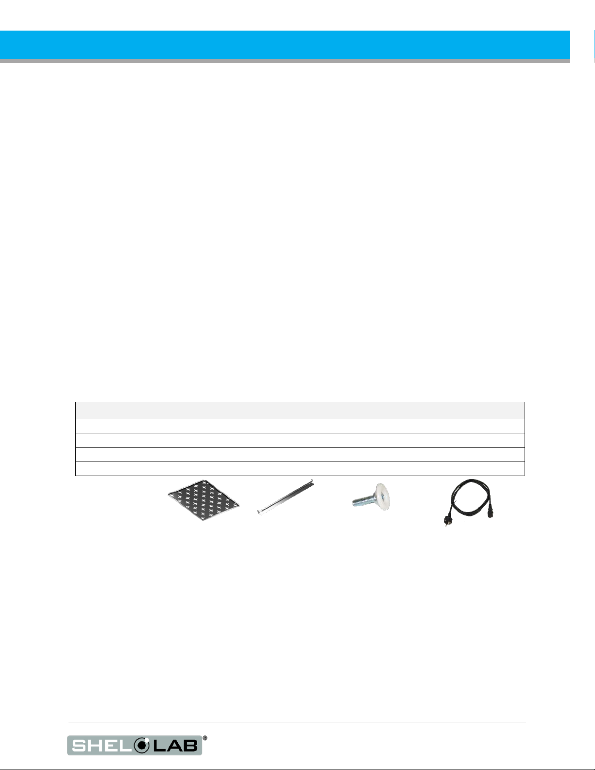
Included accessories
Model Shelves Shelf Slides Leveling Feet Power Cord
SMI2-2, SMI7-2 2 4 4 1
SMI6-2
3
6
4
1
SMI11-2
6
12
4
1
SMI12-2 6 12 4 2
6. Carefully check all packaging for accessories before discarding.

8 | Page
RECEIVING YOUR UNIT
RECORDING DATA PLATE INFORMATION
The data plate contains the incubator model number and serial number. Tech Support will need this
information during any support call. Record it below for future reference.
•The data plate is located on the top right corner of the incubation chamber door interior.
Model Number
Serial Number

9 | Page
INSTALLATION
INSTALLATION PROCEDURE CHECKLIST
Carry out the procedures and steps listed below to install the incubator in a new workspace location
and prepare it for use. All procedures are found in the Installation section of this manual.
Pre-Installation
Check that the required ambient condition for the unit are met, page 10
Check that the spacing clearance requirements are met, page 10
•Unit dimensions may be found on page 33
Check for performance-disrupting heat and cold sources in the environment, page 10
Check that a suitable electrical outlet and power supply is present, page 11
Install the Incubator in a suitable workspace location
Review the lifting and handling instructions, page 12
Make sure the incubator is level, page 12
Install the incubator in its workspace location, page 12
Set up the Incubator for use
Clean and disinfect the unit and shelving (recommended), page 12
Install the shelving, page 13
Verify the port cover has been installed on the access port, page 13
10 | Page
INSTALLATION
REQUIRED AMBIENT CONDITIONS
These units are intended for use indoors, at room temperatures between 15°C and 30°C (59°F and 86°F),
at no greater than 80% Relative Humidity(at 25°C / 77°F).
Operating these units outside of these conditions may adversely affect its incubator temperature stability
and effective operating range. For conditions outside of those listed above, please contact your SHEL LAB
distributor to explore other options suited to your laboratory or production environment.
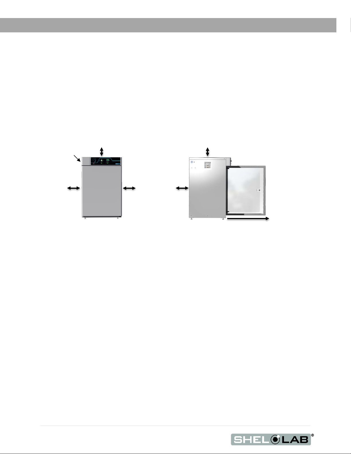
REQUIRED CLEARANCES
These clearances are required to provide air flows for ventilation and cooling.
4 inches (102mm) of clearance is required on the sides and back.
2 inches (51mm) of headspace clearance between the top of the unit and any overhead partitions.
ENVIRONMENTAL DISRUPTION SOURCES
Consider proximate environmental factors that can affect the chamber temperature and atmospheric
integrity when selecting a location to install the unit:
•Ovens, autoclaves, and any device that produces significant radiant heat
•High-traffic areas
•Direct sunlight
•Heating and cooling ducts, or other sources of fast-moving air currents
Power Cord
2” (51mm)
2” (51mm)
4” (102mm)
4” (102mm)
4” (102mm)
SMI7 30” (762mm)
All Other SMIs 26” (660mm)
Door Swing
11 | Page
INSTALLATION
POWER SOURCE REQUIREMENTS
When selecting a location for the unit, verify each of the following requirements is satisfied.
Power Source: The power source for the unit must match the voltage and match or exceed the
ampere requirements listed on the unit data plate. These units are intended for 220 - 240V
50/60 Hz applications at the following amperages:
Model Amperage Model Amperage
SMI2-2 3.0 Amps SMI7-2 5.0 Amps
SMI6-2 4.0 Amps SMI11-2 5.0 Amps
The SMI12-2 requires comes with two power cords. It requires 4.0 amps for each cord.
•Supplied voltage must not vary more than 10% from the data plate rating. Damage to the
unit may result if supplied voltage varies more than 10%.
•The wall power source must be protective earth grounded.
•Use a separate circuit to prevent loss of the unit due to overloading or circuit failure.
•The recommended wall circuit breakers for these units are 16 amps.
•The wall power source must conform to all national and local electrical codes.
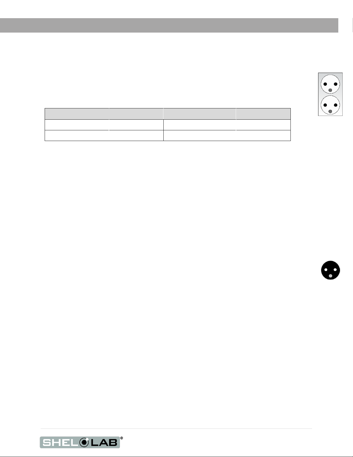
Power Cord: The unit must be positioned so that all end-users can quickly unplug the cord in the
event of an emergency.
•Each unit is provided with a 230V, 10 Amp, EUR16P, CEE 7/7, 2.5 meters (8ft 2in). always
use this cord or an identical replacement.
Fuses: These units each ship with a fuse installed in the power cord inlet and a second fuse installed
in an adjacent fuse holder.
•Both fuses must be installed and intact for the unit to operate.
•Always find and fix the cause of a blown fuse prior to putting the unit back into operation.
•Fuse type
oT3 amp, 250V, 5x20mm
Standard
CEE7/7 wall
socket.

12 | Page
INSTALLATION
LIFTING AND HANDLING
The unit is heavy. Use appropriate lifting devices that are sufficiently rated for these loads. Follow these
guidelines when lifting the unit:
•Lift the unit only from its bottom surface.
•Doors, handles, and knobs are not adequate for lifting or stabilization.
•Restrain the unit completely while lifting or transporting so it cannot tip.
•Remove all moving parts, such as shelves and trays, and lock doors in the closed position
during transfers to prevent shifting and damage.
LEVELING
Install the 4 leveling feet with the 4 corner holes on the bottom of the unit. The unit must be level and
stable for safe operation.
Note: To prevent damage when moving the unit, turn all four leveling feet so that the leg of each
foot sits inside the unit.
INSTALL INCUBATOR IN LOCATION
Install the unit in a workspace location that meets the criteria discussed in the previous entries of the
Installation section.
INSTALLATION CLEANING
Cleaning and disinfecting the incubation chamber during installation reduces the chance of microbiological
contamination. The unit was cleaned and disinfected at the factory. However, the unit may have been
exposed to contaminants during shipping. Additionally, the factory procedure may not meet the standards
of your institutional protocols. Please see the Cleaning and Disinfecting entry on page 25 in the User
Maintenance section for information on how to clean and disinfect without damaging the chamber.
•Remove all wrappings and coverings from shelving prior to cleaning and installation.
13 | Page
INSTALLATION
DEIONIZED AND DISTILLED WATER
Do not use deionized water to clean or humidify the incubator. Use of deionized water may corrode
metal surfaces and voids the warranty. The manufacturer recommends the use of distilled water in
the resistance range of 50K Ohm/cm to 1M Ohm/cm, or a conductivity range of 20.0 uS/cm to 1.0
uS/cm, for cleaning and humidifying applications.
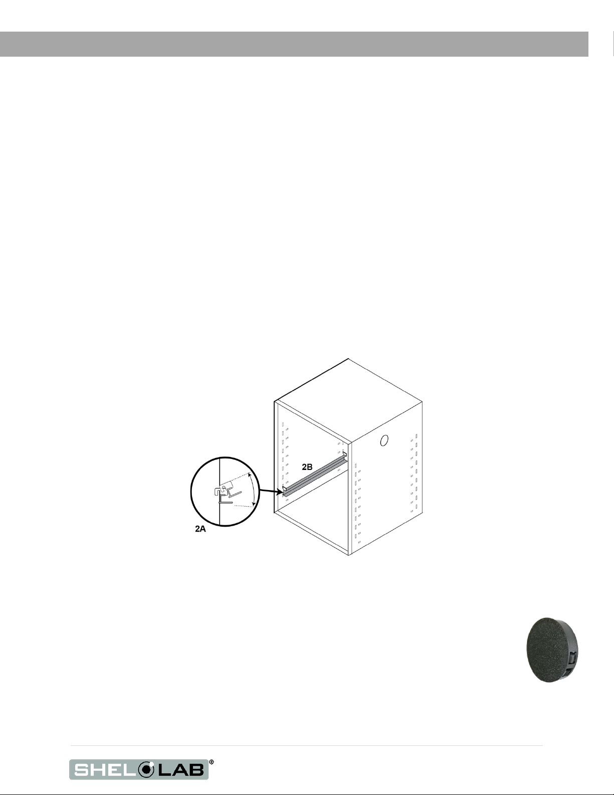
INSTALL THE SHELVING
To install the incubator shelves perform the following:
1. Hold the shelf slide at about a 10° angle. See figure 2A
2. Insert the hooked tab into the vertical slot at the desired height (Figure 2B)).
3. Push the slide into the horizontal slots.
4. Repeat for shelf slide at the same height on the opposite side of the incubator.
5. Place a shelf on the shelf slides. Repeat this procedure for additional shelves as needed.
Shelving Installation
ACCESS PORT
SMI incubators are provided with a plastic cap for the access port on the right side of the
incubation chamber. Always leave this cap in place, except when introducing sensor
probes into the chamber, such as those used for temperature calibrations. Removing the
cap during normal operations can adversely impact temperature stability and uniformity.

14 | Page
INSTALLATION

15 | Page
GRAPHIC SYMBOLS
The unit is provided with multiple graphic symbols on its exterior. The symbols identify hazards and
the functions of the adjustable components, as well as important notes in the user manual.
Symbol Definition
Consult the user manual.
Consulter le manuel d'utilisation
Temperature display
Indique l'affichage de la température
Over Temperature Limit system
Thermostat température limite contrôle haute
AC Power
Repère le courant alternatif
I/ON O/OFF
I indique que l'interrupteur est en position marche.
O indique que le commutateur est en position d'arrêt.
Protective earth ground
Terre électrique
Indicates UP and DOWN respectively
Touches de déplacements respectifs vers le HAUT et le BA
Manually adjustable
Indique un réglage manuel
Recycle the unit. Do not dispose of in a landfill.
Reycle l'unité. Ne jetez pas dans une décharge.

16 | Page
GRAPHIC SYMBOLS

17 | Page
CONTROL PANEL OVERVIEW
Figure 1: Control Panel
aOver Temperature Limit Thermostat (OTL)
The Set Over Temperature dial sets the temperature limit at which the incubator cuts off heating in
the incubation chamber. The red Over Temp Activated light illuminates when the OTL system is
rerouting power away from the heating elements. For more details, please see the Over
Temperature Limit System description in the Theory of Operations (page 19).
Power Switch
The power switch controls all power to each incubator and its systems. The green Power On light
should illuminate when the switch is in the I (on) position.
Temperature Control and Display
During normal operations, the display shows the current incubator air temperature, accurate to 0.1°C.
The Up and Down buttons are used to change display modes and then input either a new
temperature set point or a calibration adjustment. The display blinks continually while in its set point
or calibration adjustment modes, preceded by an “SP” for Set Point or “C O” for Calibration Offset.
The Heating indicator light illuminates when the incubator powers the chamber heating elements.

18 | Page
CONTROL PANEL OVERVIEW

19 | Page
OPERATION
THEORY OF OPERATION
The SMI general purpose incubators are engineered to provide constant temperature incubation
environments. Each unit can obtain a stable, uniform temperature in its chamber, ranging from the
room temperature (ambient) +8°C up to 70°C for incubation applications. Each incubator features an
inner glass viewing door that allows visual inspection of samples without compromising the chamber
temperature environment. Each incubator unit in an SMI12 is independently powered and heated.
Heating
Each incubator is controlled by a microprocessor board with heating elements attached to the incubation
chamber walls and a solid-state temperature sensor probe inside the chamber. The processor employs
proportional-integral-derivative analytical feedback-loop functions when measuring and controlling the
chamber air temperature. PID-controlled heating pulse intensities and lengths are proportional to the
difference between the measured chamber temperature and the set point. The set point is the desired
operating temperature entered by the user. The frequency of pulses is derived from the rate of change in
the difference. The integral function slows the rate of pulses when the temperature nears the set point in
order to prevent overshooting.
The PID functions are also used to optimize incubator warming rates for hotter or cooler environments.
Heat loss from leaving the incubator doors open for long periods of time (an hour or more) can trick the
controller into operating as though in a cool environment. This can result in a period of temperature
overshoots.
Each incubator relies on natural heat radiation for cooling. An incubator can achieve a low-end
temperature of the ambient room temperature +8°C. The fan inside in the incubator aids in maintaining air
circulation and a uniform air temperature in the incubation space.
The chamber door is self-heating to bolster the thermal uniformity and stability of the chamber and to
minimize condensation on the glass viewing door. The glass door will cool while the chamber door is
opening, eventually leading to condensate on the door and impacting the chamber temperature
stability and uniformity. Minimize sample viewing times when possible.
The Over Temperature Limit System
The OTL is a mechanical heating cutoff included with each incubator and operates independently of the
incubator microprocessor controller. The OTL helps safeguard samples by preventing runaway heating in
the event of a hardware failure in the microprocessor controller or a sudden external heat spike. The OTL
is connected to a hydrostatic sensor probe located inside the incubator and is intended to be set by the
user to approximately 1°C above the current operating temperature set point.
If the incubator temperature exceeds the OTL cutoff setting, the OTL will route power away from the
incubator heating elements. It will continue to do so as long as the incubator air temperature is higher
than the present OTL cutoff setting. A red indicator illuminates when the OTL is rerouting power.
20 | Page
OPERATION
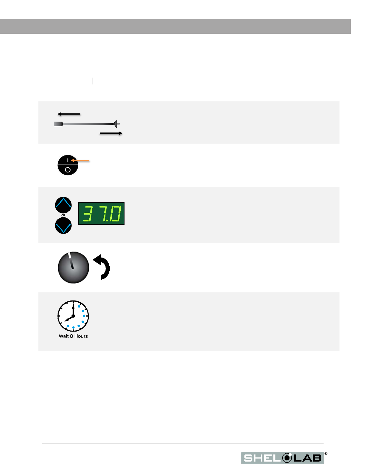
PUT THE INCUBATOR INTO OPERATION
Carry out the following steps and procedures to put the unit into operation after installing it in a new
workspace environ
ment.
End of procedure
1.
2.
Attach the power cord that came with the unit to the power inlet
receptacle on the side of the incubator.
Plug the power cord into the workspace electrical supply outlet.
3.
Place the incubator Power Switch in the on ( I ) position.
•The Power light illuminates
•The Temperature display illuminates
4.
Set the Temperature the Set Point to your incubation application
temperature.
•See page 21
5.
Set the Over Temperature Limit. See page 22.
The incubator must be heated and stable at your application temperature to
perform this procedure.
Allow the unit to run 8 hours (overnight) prior to:
•Loading Samples, page 23
•Verifying the accuracy or calibrating the incubator
temeprature display.
This manual suits for next models
4
Table of contents
Other Shel lab Laboratory Equipment manuals


Popular Laboratory Equipment manuals by other brands

MMM Group
MMM Group CO2Cell 190 Standard Instructions for use

Selecta
Selecta AGIMATIC ED instruction manual

Mold-Masters
Mold-Masters TempMaster M3 Series user manual

Labnet
Labnet Spectrafuge 24D instruction manual

Metrohm
Metrohm 942 Extension Module Vario LQH manual

Radleys
Radleys Reactor-Ready Lab Reactor instructions


