Sherline Products 4417Z User manual
NOTE: These instructions accompany both the CNC
lathe already fitted with the locking system and the
retrofit kit for installing the lock on an existing lathe. If
you have a lathe already fitted with the system, only the
first part of the instructions regarding purpose and use
will be applicable.
The purpose of the leadscrew backlash lock
CNC machining operations require precise leadscrew
movement to producing a good part. The normal backlash
of.003"to.005"canbeunacceptableinthesesituationsand
a way was needed to reduce backlash to the .001" to .002"
range.ThissolutionwasdevelopedfortheZ-axisonthemill,
but it has been adapted here to work on the lathe as well.
BecauseIdesignedthislevertolockthecolumnleadscrew
acouple of yearsago, I neverthought of itas an optionthat
could be used to control backlash; however, early one
morningIfinallyrealizedhowtousethislockcouldbeused
inthisway,andwehadaprototypeworkingthenextdayand
were into production within a week. I’m also pleased to
report that the anti-backlash system can be added to every
Sherlinelatheever built!
By locking this lever against the saddle nut, it keeps the
leadscrewfrom turning oncetheheadstockis positioned at
theproperheightfortheoperation.Thisnewleverpositioning
system will allow you to position the locking lever in a
partiallylockedposition,removingasmuchbacklashasyou
desire, and then it can be locked in that position. As wear
occurs, the position of the locking lever can be adjusted.
Using the Z-axis lock on a CNC lathe
The locking arm is clamped in the lock plate for shipping.
Loosen the SHCS that holds it and remove the plastic arm.
Insert the pin in the end of the plastic lever into the hole in
the end of the brass Z-axis locking lever from the bottom
side.Alignthelockingarmwiththeslotinthelockplateand
slipitin.Movethebrasslockinglevertoprovidethedesired
amount of backlash. Tighten the thumbscrew to hold the
plasticarminposition.Donotovertightenthethumbscrew.
There is not a lot of force trying to move the arm. The arm
serves only to hold the locking lever in position once you
have adjusted it.
The brass locking lever is adjusted by hand as shown in
Figure 1, and then the positioning arm is locked in place.
Don't adjust the locking lever by moving the plastic arm
CNC Lathe Leadscrew Backlash Lock
P/N 4417Z/4417ZM
SHERLINE
PRODUCTS
INCORPORATED 1974
9/3/08
SHERLINEPRODUCTSINC.ˆ 3235ExecutiveRidge ˆ Vista ˆ California92081-8527ˆ FAX:(760)727-7857
TollFreeOrderLine:(800)541-0735 ˆ International,LocalorTech.Assistance:(760)727-5857 ˆ Internet:www.sherline.com
directly. You will have much better feel for the amount of
pressureneededbyadjustingthelockingleveritself,andthe
plastic pin that engages the hole in the locking lever is not
designed to exert a lot of pushing/pulling force.
Installing a new saddle nut and locking lever on a CNC
mill not currently fitted with a locking lever
Sherlinelatheshaveneverbeenfittedwithlockingleverson
the leadscrew. This system was developed specifically for
use on CNC machines. The new retrofit installation kit
includes a new locking lever and a new saddle nut without
aspring loadedball to holdit inthe unlocked position.The
positive locking arm allows partial locking of the lever to
reduce backlash to a minimum. The small detent in the
locking lever that was formerly used to engage a spring-
loaded ball has been retained to indicate the side of the
locking lever that should be facing the saddle nut. (If the
lockinglevershouldfailtolockagainstthesaddlenutwithin
theavailablearcinthebackofthemillcolumn,checktosee
if the lever has been installed backwards.) Install the new
saddle nut and lever as follows:
1. Remove the headstock and tailstock from the lathe.
LOCK PLATE
BODY
P/N44171
ADJUSTINGARM
P/N40173
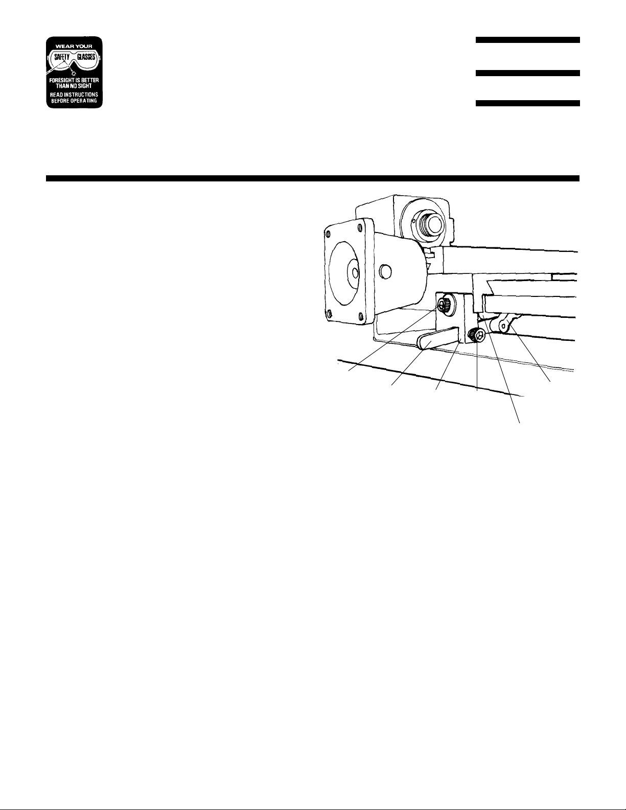
FIGURE 1—Components of the lever locking system as
they are now installed on new Sherline CNC lathes.
10-32x7/8"SHCS
P/N40740 BRASSLOCKING
LEVERP/N 44172/
44173
BRASSSADDLENUTP/N40174/41174
10-32x3/8"
SHCS
P/N40510
2. Remove the socket head cap screw that attaches the
saddle nut to the saddle.
3. Turn the lathe upside down and remove the single cap
screw at each end that holds the leadscrew thrusts to the
base.Notethenumberandlocationofanywasherspresent.
They are spacers and will need to be returned to the same
positionwhenreassembling.Turnbackoverandliftoffthe
bed, thrust and leadscrew assembly.
4. Crank the handwheel so the saddle nut moves to the end
of the leadscrew as far from the handwheel as possible.
5. Remove the countersunk screw in the bed that secures
thethrustatthehandwheelend.Thiswillallowyoutoslide
the leadscrew out of the other thrust and remove the
handwheel/leadscrew assembly from the bed.
6. Unscrew the old saddle nut from the leadscrew. Thread
the new locking lever first with the machined side or ball
detent side facing away from the handwheel. Then thread
the new saddle nut onto the leadscrew. Make sure the
saddlenutisinstalledfacinginthesamedirectionastheone
youpreviouslyremoved.Oncebothlockingleverandsaddle
nut are installed, screw them onto the leadscrew to the
approximatepositionoftheoldnutandleavethemjustlightly
touching each other but not locked.
6. In the reverse order from how you removed them,
reattach the leadscrew and thrust to the bed and then the
bedassemblytothebase.Remembertoreinstallanyspacer
washers in their original positions. Slide the saddle into
positionsotheholealignswiththeholeinthenewsaddlenut.
7. Using the new, longer socket head screw and washer
provided,feedthescrewthroughtheholeinthenewlocking
plate, through the hole in the saddle and into the threaded
hole in the saddle nut to reattach it. (See Figure 2.)
8.Insertthepinofthe plastic arm into theholeintheendof
the brass locking lever as shown in Figure 2. Slide the arm
into the slot on the bottom of the locking plate. Adjust it as
noted on side one of this sheet and secure it in the desired
position using the 10-32 x 3/8" SHCS.
Adjusting the saddle nut alignment
Whenyoureinstalled the new saddlenutinplace of the old
one,thetwoadjustingsetscrewswereleft in theirprevious
adjustmentpositions.Ifbindingoccursinthenewinstallation,
it will be necessary to readjust the new saddle nut on the
leadscrew using the two set screws on either side of the
attachment screw. To do this you will first need to remove
the locking plate to get access to these set screws. Then, to
adjustthesaddleitshouldfirstbepositionedattheendofits
travel as close to the handwheel as possible. Remove the
lockplateandlooselyinstalltheoriginalshorterscrewthat
attached the saddle to the old saddle nut. Bring each set
screw into light contact with the new saddle nut and
retighten the attaching screw. If binding occurs when you
turn the handwheel, readjust the two set screws until the
leadscrew moves freely. Then remove the old attachment
screw and reinstall the locking plate using the new, longer
screw.
Weare attemptingto adjustthe saddle nutso itrides on the
leadscrew with the minimum amount of drag. You can
check the drag by turning the leadscrew handwheel. If you
feel excessive drag, tighten or loosen a single set screw
while moving the saddle with the handwheel until the
handwheel turns freely, but keep the saddle close to the
handwheel. (If you adjust the saddle nut while it is in the
centeroftheleadscrew,itmaybeslightlyoffcenterbutwill
feelfreeuntilthesaddlegetsclosetoeitherendofitstravel.
Here, the leadscrew is supported and cannot deflect so it
willbindthemost.)Ifyoucan'teliminatethebinding,tapthe
saddle nut with a plastic hammer on the leadscrew side
while the saddle nut is tightly attached to the saddle and
readjust. Don't use the machine with a loose attachment
screw, as this will cause excessive wear and backlash.
Joe Martin, President and Owner
Sherline Products Inc.
4417Z, Page 2 of 2
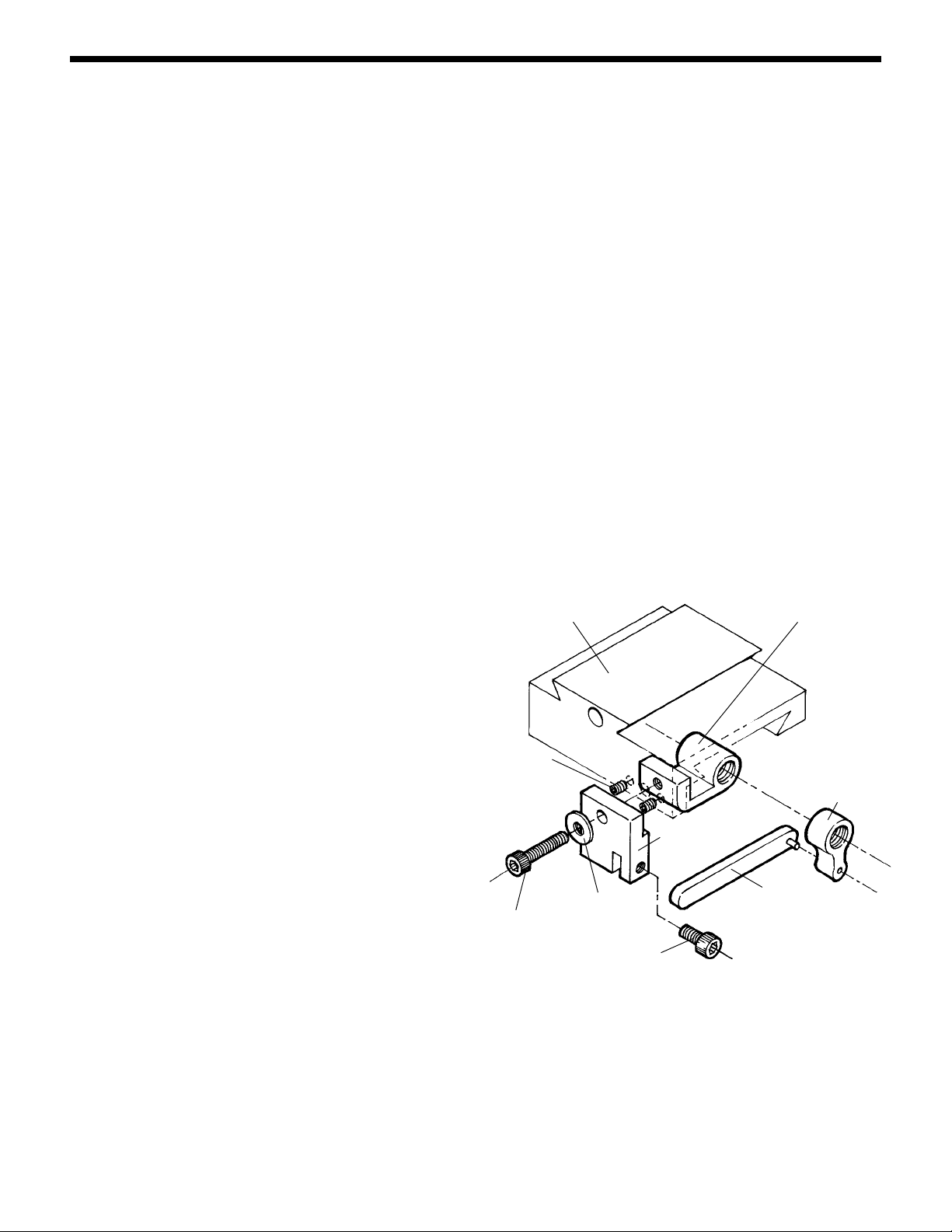
44171LOCK
PLATE BODY
4074010-32
x 7/8" SHCS
FIGURE 2—Exploded view shows saddle nut and locking
plate in relation to lathe saddle. Lever arm goes through
slot in lock plate body and is held in position by 3/8"
SHCS after adjusting.
40173
ADJUSTMENT
LEVER
44172/44173
BRASS LOCKING
LEVER
(Detent faces
saddle nut)
40174/41174 SADDLE NUT
40510 10-32 x 3/8" SHCS
406603/16"
WASHER
EXPLODED VIEW AND PARTS LIST
SADDLENUT
ADJUSTMENT
SCREWS
LATHE
SADDLE
This manual suits for next models
1


