nl lock Duet RotoBolt RR40 User manual
RR40•20 Technical Manual
CHARACTERISTICS
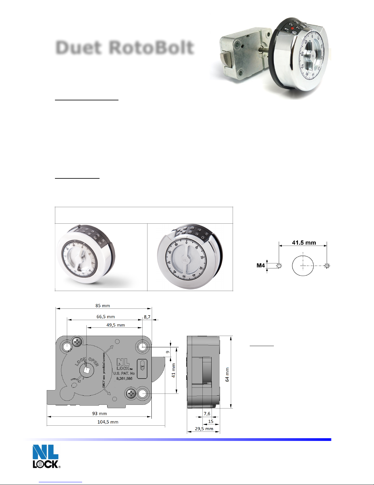
The Duet Rotobolt is an Electronic RotoBolt Lock with a manipulation-resistant 4-wheel
mechanical combination override. It can be mounted in all four mounting directions. The Basic
Electronics feature a 6-digit Main code that can be changed by the user. With the main code a
secondary code can be activated and deleted. If a valid code has been entered, the lock
electronic removes the blocking for 3 seconds and the boltwork can be moved into OPEN position
by pushing the bolt inside the lock case. When moving the boltwork into LOCKED position the
RotoBolt automatically secures. Mechanical openings follow standard 4-wheel locks operating
procedures through entry integrated mechanical dial.
ENTRY UNITS
The Duet Rotobolt is compatible with the following NL LOCK Entry units (separate technical
descriptions for Entry units are available). Entry unit cable hole on the safe door does not have to
exceed 12 mm diameter
!
RR40•20 Technical Manual rev. 170528
© 2017 Lock Technology Page !of !1 4
Duet Series:
DI20 DB20
!
Duet RotoBolt
Important:
•Modifications to the lock (including
lock bolt attachments) are not
allowed, and will void the
manufacturer’s warranty and
Standards approvals.
•No through holes on the safe door
are allowed within the lock body area.
•Lock body area should be protected
against destructive attacks

BOLTWORK REQUIREMENTS and MOUNTING SPECIFICATIONS
If the Duet Rotobolt lock is used in conjunction with another lock, the boltwork must be constructed in a
way that the Universal secures first.
In the LOCKED position the distance between the Universal bolt and the boltwork part that is moving the
lock bolt should be approximately 1 mm.
Only use NL LOCK supplied screws (M6) to mount the lock. Lock has to be mounted on secure storage metal
(preferred steel) units only. Tighten the screws securely so the lock body is attached firmly to the mounting
surface. Use of screw locking glue (i.e. Loctite) is recommended.
Security relevant parts of a HSL should not be accessible to unauthorized persons when the door of the
secure storage unit to which it is fitted is open"
Test Electronics
Like all locks from NL LOCK this unit includes a unique feature to functionally test the electronics:
Function #5
Functional Test
•Enter code (i.e. 1-2-3-4-5-6). The lock emits a double signal for the correct code.
•Turn boltwork handle towards OPEN position.
The bolt rotates into the housing. Bolt must move freely.
•Turn handle towards Locked position.
The lock bolt must fully extend and secure.
•Make sure there is an air space on all sides of the lock bolt when the safe’s boltwork is fully thrown
into locked position.
IMPORTANT: Perform the functional test several times before locking the safe door.!
RR40•20 Technical Manual rev. 170528
© 2017 Lock Technology Page !of !2 4
STEP
TASK
REMARK
1
Press and hold [5] until a double
signal sounds and the light stays ON.
2
Enter the all keys in exactly this
sequence:
[1]-[2]-[3]-[4]-[5]-[6]-[7]-[8]-[9]-[0]
Push buttons slowly so you recognize the signaling of the
lock. A double signal indicates that the keypad and the lock
communicate and perform properly.
A long signal indicates that the electronics may be damaged.
Lock bolt operations only allowed as described
into the drawing and max load should not
exceed 1KN.
min 1.5 mm.
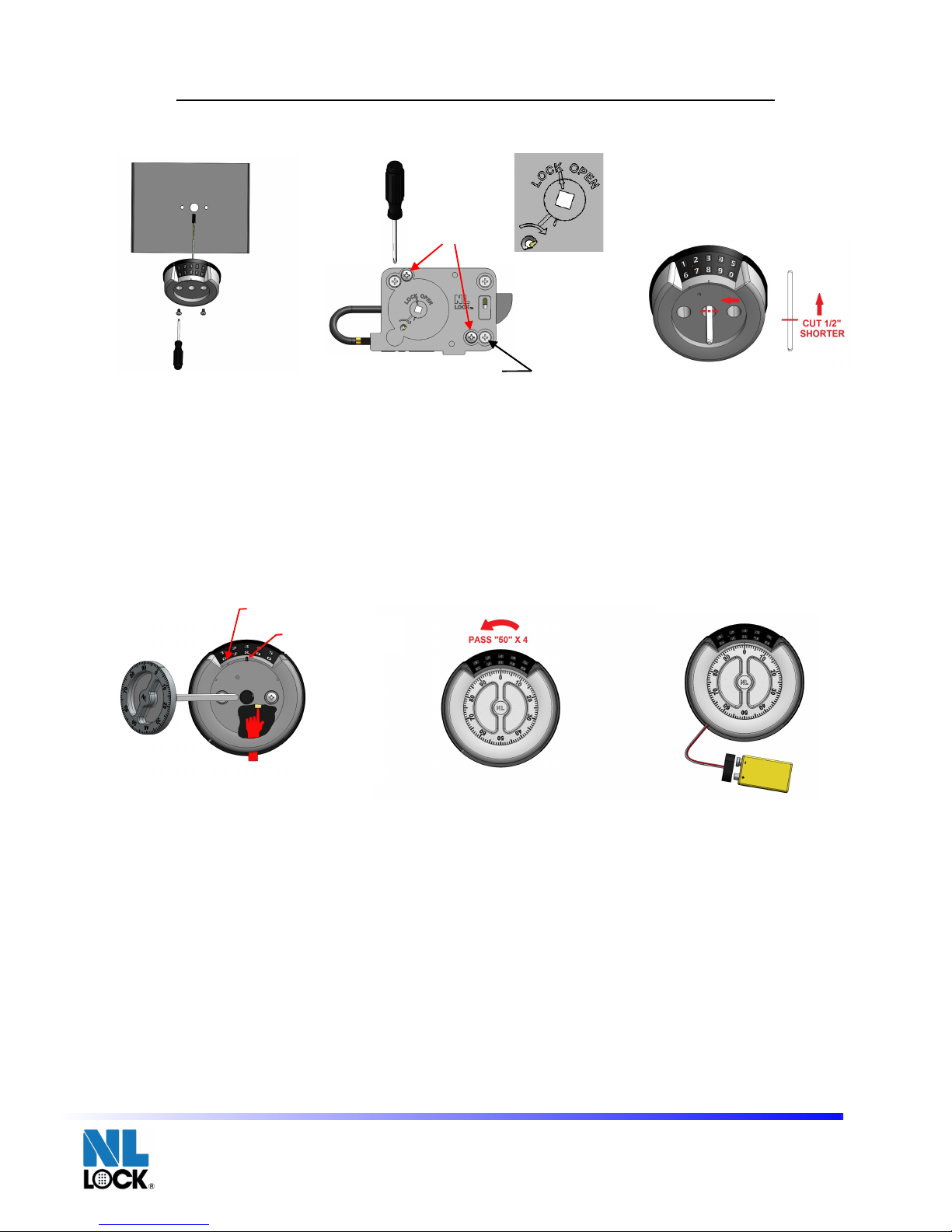
Step 1. Put the input cable through the center hole of the safe door. Using the mounting screws, mount the
input onto the safe door. Tighten the screws.
Step 2. Using the mounting screws, mount the lock in the correct posi on on the inside of the safe door. Plug
the input connector into the ENT slot on the lock. LOCK CAM MUST BE IN THE “LOCK OPEN” POSITION.
Step 3. Insert the dial shaft into the lock un l it stops on lock cam. YOU MUST MAKE SURE THE DIAL SHAFT
IS FULLY INSERTED BY LOOKING IN THE LOCK CAM FROM THE INSIDE OF THE SAFE DOOR. Mark the dial
shaft at the surface marked by arrow. Pull out dial shaft and measure an additional 1/2” (12.7mm) shorter
from the dial shaft mark. Cut the dial shaft and remove the sharp edges.
Step 4. Put dial onto dial shaft and slide it into the input un l the dial stops. Make sure the dial number “92”
is lined up with the center mark (opening index). From the inside of the battery compartment, press in the
butt on fully and hold. Finish installing the dial by pushing the dial in and release the button.
Step 5. Dial the combina on by turning the dial LEFT and pass “50” four times and stop exactly on “50” the
fi h me on the opening index. Turn RIGHT and stop on “92”. Then turn the SAFE HANDLE to open the lock.
Note: Due to installa on tolerances, it is possible that the code may have shifted up or down two numbers.
This shifting is normal and will be eliminated once the code is reset. If the lock does not open on “50”, try to
open at “48” then “49”, “51”, or “52”. Due to these tolerances, it is important to reset the code a er installa-
on.
Step 6. Place 9V alkaline battery (Duracell TM) into the bottom compartment of the input and close the
compartment door.
Step 7. (No Illustration) Enter the preset combination ELECTRONICALLY (5-5-5-5-5-5) and turn the SAFE
HANDLE to open the lock.!
RR40•20 Technical Manual rev. 170528
© 2017 Lock Technology Page !of !3 4
!
Installation Instructions 071717
Page 1 of 1
"#$%!&'!()#!#*$!+,%)#!-./0$!#*12)3*!#*$!-$,#$1!*20$!24!#*$!5.4$!6221'!75+,3!#*$!82),9,3!5-1$:5;!82),#!#*$!
+,%)#!2,#2!#*$!5.4$!6221'!<+3*#$,!#*$!5-1$:5'!
"#$%!='!75+,3!#*$!82),9,3!5-1$:5;!82),#!#*$!02->!+,!#*$!-211$-#!%25+92,!2,!#*$!+,5+6$!24!#*$!5.4$!6221'!(0)3!
#*$!+,%)#!-2,,$-#21!+,#2!#*$!?@<!502#!2,!#*$!02->'!
LOCK CAM MUST BE IN THE “LOCK OPEN” POSI-
TION.
"#$%!A'!B,5$1#!#*$!6+.0!5*.C!+,#2!#*$!02->!),90!+#!5#2%5!2,!02->!-.8'!
YOU MUST MAKE SURE THE DIAL
SHAFT IS FULLY INSERTED BY LOOKING IN THE LOCK CAM FROM THE INSIDE OF THE SAFE
DOOR.!
D.1>!#*$!6+.0!5*.C!.#!#*$!5)14.-$!8.1>$6!/E!.112:'!!()00!2)#!6+.0!5*.C!.,6!8$.5)1$!.,!.66+92,.0!
&F=G!H&='I88J!5*21#$1!4128!#*$!6+.0!5*.C!8.1>'!K)#!#*$!6+.0!5*.C!.,6!1$82L$!#*$!5*.1%!$63$5'!
!
"#$%!&!
"#$%!M!
"#$%!N!
"#$%!A!
"#$%!=!
"#$%!N'!()#!6+.0!2,#2!6+.0!5*.C!.,6!50+6$!+#!+,#2!#*$!+,%)#!),90!#*$!6+.0!5#2%5'!D.>$!5)1$!#*$!6+.0!,)8/$1!OP=G!
+5!0+,$6!)%!:+#*!#*$!-$,#$1!8.1>!H2%$,+,3!+,6$QJ'!R128!#*$!+,5+6$!24!#*$!/.S$1E!-28%.1#8$,#;!%1$55!+,!#*$!
/)S2,!4)00E!.,6!*206'!R+,+5*!+,5#.00+,3!#*$!6+.0!/E!%)5*+,3!#*$!6+.0!+,!.,6!1$0$.5$!#*$!/)S2,'!!!
"#$%!T'!U+.0!#*$!-28/+,.92,!/E!#)1,+,3!#*$!6+.0!V?R<!.,6!%.55!OTWG!42)1!98$5!.,6!5#2%!$Q.-#0E!!2,!OTWG!#*$!
XC*!98$!2,!#*$!2%$,+,3!+,6$Q'!<)1,!YBZ[<!.,6!5#2%!2,!OP=G'!<*$,!#)1,!#*$!
SAFE HANDLE
#2!2%$,!#*$!
02->'!!
@2#$\!U)$!#2!+,5#.00.92,!#20$1.,-$5;!+#!+5!%255+/0$!#*.#!#*$!-26$!8.E!*.L$!5*+C$6!)%!21!62:,!#:2!,)8/$15'!
<*+5!5*+C+,3!+5!,218.0!.,6!:+00!/$!$0+8+,.#$6!2,-$!#*$!-26$!+5!1$5$#'!B4!#*$!02->!62$5!,2#!2%$,!2,!OTWG;!#1E!#2!
2%$,!.#!ON]G!#*$,!ONPG;!OT&G;!21!OT=G'!U)$!#2!#*$5$!#20$1.,-$5;!+#!+5!+8%21#.,#!#2!1$5$#!#*$!-26$!.C$1!+,5#.00.^
92,'!
"#$%!M'!(0.-$!P_!.0>.0+,$!/.S$1E!HU)1.-$00!`J!+,#2!#*$!/2S28!-28%.1#8$,#!24!#*$!+,%)#!.,6!-025$!#*$!-28^
%.1#8$,#!6221'!
"#$%!I'!H@2!B00)5#1.92,J!?,#$1!#*$!%1$5$#!-28/+,.92,!
ELECTRONICALLY
!HT^T^T^T^T^TJ!.,6!#)1,!#*$!
SAFE
HANDLE
!#2!2%$,!#*$!02->'!!
®
!
Lock Technology
!
Redundant RotoBolt Installation Instructions - Dual Basic (DB20•XX)
"#$%!T!
!
CHANGE INDEX
OPENING INDEX
DO NOT MOVE LOCK
CAM FROM THIS
POSITION DURING
ENTIRE INSTALL.
MOUNTING SCREW (3 REQ’D)
ASSEMBLY
SCREWS
!
Installation Instructions 071717
Page 1 of 1
"#$%!&'!()#!#*$!+,%)#!-./0$!#*12)3*!#*$!-$,#$1!*20$!24!#*$!5.4$!6221'!75+,3!#*$!82),9,3!5-1$:5;!82),#!#*$!
+,%)#!2,#2!#*$!5.4$!6221'!<+3*#$,!#*$!5-1$:5'!
"#$%!='!75+,3!#*$!82),9,3!5-1$:5;!82),#!#*$!02->!+,!#*$!-211$-#!%25+92,!2,!#*$!+,5+6$!24!#*$!5.4$!6221'!(0)3!
#*$!+,%)#!-2,,$-#21!+,#2!#*$!?@<!502#!2,!#*$!02->'!
LOCK CAM MUST BE IN THE “LOCK OPEN” POSI-
TION.
"#$%!A'!B,5$1#!#*$!6+.0!5*.C!+,#2!#*$!02->!),90!+#!5#2%5!2,!02->!-.8'!
YOU MUST MAKE SURE THE DIAL
SHAFT IS FULLY INSERTED BY LOOKING IN THE LOCK CAM FROM THE INSIDE OF THE SAFE
DOOR.!
D.1>!#*$!6+.0!5*.C!.#!#*$!5)14.-$!8.1>$6!/E!.112:'!!()00!2)#!6+.0!5*.C!.,6!8$.5)1$!.,!.66+92,.0!
&F=G!H&='I88J!5*21#$1!4128!#*$!6+.0!5*.C!8.1>'!K)#!#*$!6+.0!5*.C!.,6!1$82L$!#*$!5*.1%!$63$5'!
!
"#$%!&!
"#$%!M!
"#$%!N!
"#$%!A!
"#$%!=!
"#$%!N'!()#!6+.0!2,#2!6+.0!5*.C!.,6!50+6$!+#!+,#2!#*$!+,%)#!),90!#*$!6+.0!5#2%5'!D.>$!5)1$!#*$!6+.0!,)8/$1!OP=G!
+5!0+,$6!)%!:+#*!#*$!-$,#$1!8.1>!H2%$,+,3!+,6$QJ'!R128!#*$!+,5+6$!24!#*$!/.S$1E!-28%.1#8$,#;!%1$55!+,!#*$!
/)S2,!4)00E!.,6!*206'!R+,+5*!+,5#.00+,3!#*$!6+.0!/E!%)5*+,3!#*$!6+.0!+,!.,6!1$0$.5$!#*$!/)S2,'!!!
"#$%!T'!U+.0!#*$!-28/+,.92,!/E!#)1,+,3!#*$!6+.0!V?R<!.,6!%.55!OTWG!42)1!98$5!.,6!5#2%!$Q.-#0E!!2,!OTWG!#*$!
XC*!98$!2,!#*$!2%$,+,3!+,6$Q'!<)1,!YBZ[<!.,6!5#2%!2,!OP=G'!<*$,!#)1,!#*$!
SAFE HANDLE
#2!2%$,!#*$!
02->'!!
@2#$\!U)$!#2!+,5#.00.92,!#20$1.,-$5;!+#!+5!%255+/0$!#*.#!#*$!-26$!8.E!*.L$!5*+C$6!)%!21!62:,!#:2!,)8/$15'!
<*+5!5*+C+,3!+5!,218.0!.,6!:+00!/$!$0+8+,.#$6!2,-$!#*$!-26$!+5!1$5$#'!B4!#*$!02->!62$5!,2#!2%$,!2,!OTWG;!#1E!#2!
2%$,!.#!ON]G!#*$,!ONPG;!OT&G;!21!OT=G'!U)$!#2!#*$5$!#20$1.,-$5;!+#!+5!+8%21#.,#!#2!1$5$#!#*$!-26$!.C$1!+,5#.00.^
92,'!
"#$%!M'!(0.-$!P_!.0>.0+,$!/.S$1E!HU)1.-$00!`J!+,#2!#*$!/2S28!-28%.1#8$,#!24!#*$!+,%)#!.,6!-025$!#*$!-28^
%.1#8$,#!6221'!
"#$%!I'!H@2!B00)5#1.92,J!?,#$1!#*$!%1$5$#!-28/+,.92,!
ELECTRONICALLY
!HT^T^T^T^T^TJ!.,6!#)1,!#*$!
SAFE
HANDLE
!#2!2%$,!#*$!02->'!!
®
!
Lock Technology
!
Redundant RotoBolt Installation Instructions - Dual Basic (DB20•XX)
"#$%!T!
!
CHANGE INDEX
OPENING INDEX
DO NOT MOVE LOCK
CAM FROM THIS
POSITION DURING
ENTIRE INSTALL.
MOUNTING SCREW (3 REQ’D)
ASSEMBLY
SCREWS
DUET ROTOBOLT INSTALLATION INSTRUCTIONS - DB20-XX ENTRY
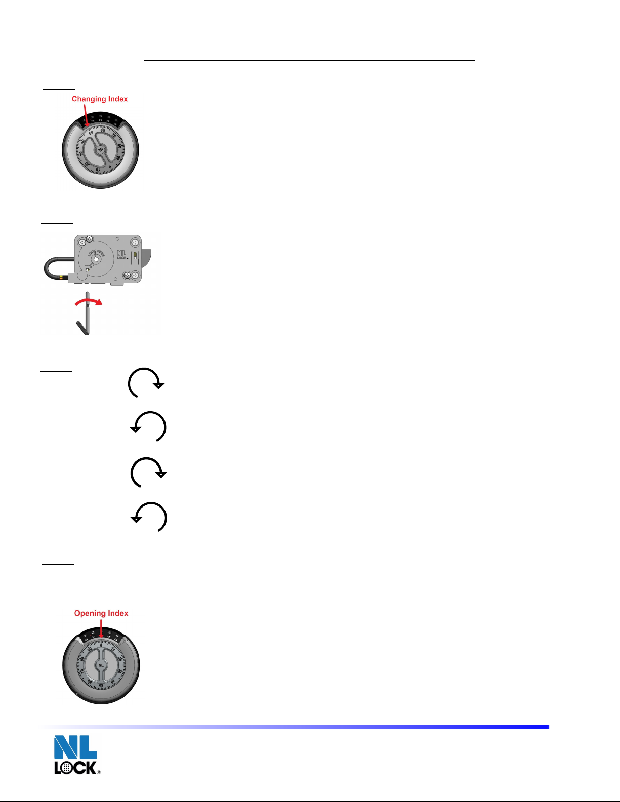
Using the changing index, turn the dial to the le and pass “50” five (5) times and
then stop exactly on “50” the sixth me.
Insert the change key into the hole marked with the arrow. Make sure that the
change key is fully inserted and turn it to the right. DO NOT FORCE THE CHANGE
KEY.
Dial the new combination to the changing index. Important: no simple codes
which are easy to guess (e.g. 10-20-30-40) nor personal data (e.g. birthdays) or
other data that could be derived from having knowledge about the code holder shall
be chosen. Never write the code down. Keep it secret!
Turn right, pass first combination number four times and stop exactly on the
number on the Changing Index the fifth time.
Turn left, pass second combination number three times and stop exactly on the
number on the Changing Index the fourth time.
Turn right, pass third combination number twice and stop exactly on the num- ber
on the Changing Index the third time.
Turn left, pass fourth combination number once and stop exactly on the number on
the Changing Index the second time.
While holding the dial in place, turn the change key to the left and pull it out from
the lock. If you do not hold the dial while doing this, it may cause the wheels to
move and your combination will not work.
Before closing the safe door, dial the new combination to the opening index using
the dialing sequence in Step 3. After complete combination is entered, turn dial to
the right and stop on “92” and then turn the safe handle to open the lock.
RR40•20 Technical Manual rev. 170528
© 2017 Lock Technology Page !of !4 4
!
Changing Instructions 071717
Page 1 of 1
"#$%&!'()!*(+%&$%&!$%,)-.!'/0%!'()!,$+1!'2!'()!1)3!+%,!4+##!5678!9:)!;6<!=>)#!
+%,!'()%!#'24!)-+*'1?!2%!5678!'()!#$-'(!=>)@!
!
!
!
!
!
!
A%#)0'!'()!*(+%&)!B)?!$%'2!'()!(21)!>+0B),!C$'(!'()!+002C@!D+B)!#/0)!'(+'!'()!
*(+%&)!B)?!$#!E/11?!$%#)0'),!+%,!'/0%!$'!'2!'()!0$&('@!DO NOT FORCE THE CHANGE
KEY.
!
!
!
!
!
F$+1!'()!%)C!*2>G$%+=2%!'2!'()!*(+%&$%&!$%,)-@!! !
H/0%!0$&('.!4+##!90#'!*2>G$%+=2%!%/>G)0!E2/0!=>)#!+%,!#'24!)-+*'1?!2%!'()!
%/>G)0!2%!'()!I(+%&$%&!A%,)-!'()!93(!=>)@!
H/0%!1)3.!4+##!#)*2%,!*2>G$%+=2%!%/>G)0!'(0))!=>)#!+%,!#'24!)-+*'1?!2%!'()!
%/>G)0!2%!'()!I(+%&$%&!A%,)-!'()!E2/0'(!=>)@!
H/0%!0$&('.!4+##!'($0,!*2>G$%+=2%!%/>G)0!'C$*)!+%,!#'24!)-+*'1?!2%!'()!%/>J
G)0!2%!'()!I(+%&$%&!A%,)-!'()!'($0,!=>)@!
H/0%!1)3.!4+##!E2/0'(!*2>G$%+=2%!%/>G)0!2%*)!+%,!#'24!)-+*'1?!2%!'()!%/>G)0!
2%!'()!I(+%&$%&!A%,)-!'()!#)*2%,!=>)@!
!
K($1)!(21,$%&!'()!,$+1!$%!41+*).!'/0%!'()!*(+%&)!B)?!'2!'()!1)3!+%,!4/11!$'!2/'!
E02>!'()!12*B@!AE!?2/!,2!%2'!(21,!'()!,$+1!C($1)!,2$%&!'($#.!$'!>+?!*+/#)!'()!
C())1#!'2!>2:)!+%,!?2/0!*2>G$%+=2%!C$11!%2'!C20B@!
!
!
!
L)E20)!*12#$%&!'()!#+E)!,220.!,$+1!'()!%)C!*2>G$%+=2%!'2!'()!24)%$%&!$%,)-!/#J
$%&!'()!,$+1$%&!#)M/)%*)!$%!N')4!O@!P3)0!*2>41)')!*2>G$%+=2%!$#!)%')0),.!turn
dial to the right and stop on “92” and then turn the external handle to open
the lock.!
Redundant RotoBolt 4-Wheel Changing Instructions
Step 1
Step 2
®
!
Lock Technology
!
6-!
Q-!
O-!
R-!
Step 5
Step 3
Step 4
MECHANICAL COMBINATION CHANGING INSTRUCTIONS
This manual suits for next models
1
Other nl lock Lock manuals

Popular Lock manuals by other brands


Clavis
Clavis Alpha Series User instructions

ZKTeco
ZKTeco AL20B user manual

Siegenia-AUBI
Siegenia-AUBI TSBR0030 quick start guide

ArrowVision
ArrowVision Shepherd 210 Operation manual

Simons Voss Technologies
Simons Voss Technologies SmartHandle AX manual

Simons Voss Technologies
Simons Voss Technologies LockNode SREL2.G2 quick guide