Sentrilock NXT-M User manual

SentriLock NXT-BLE Installation Manual – 2019 v3
Installation Manual
Product Items
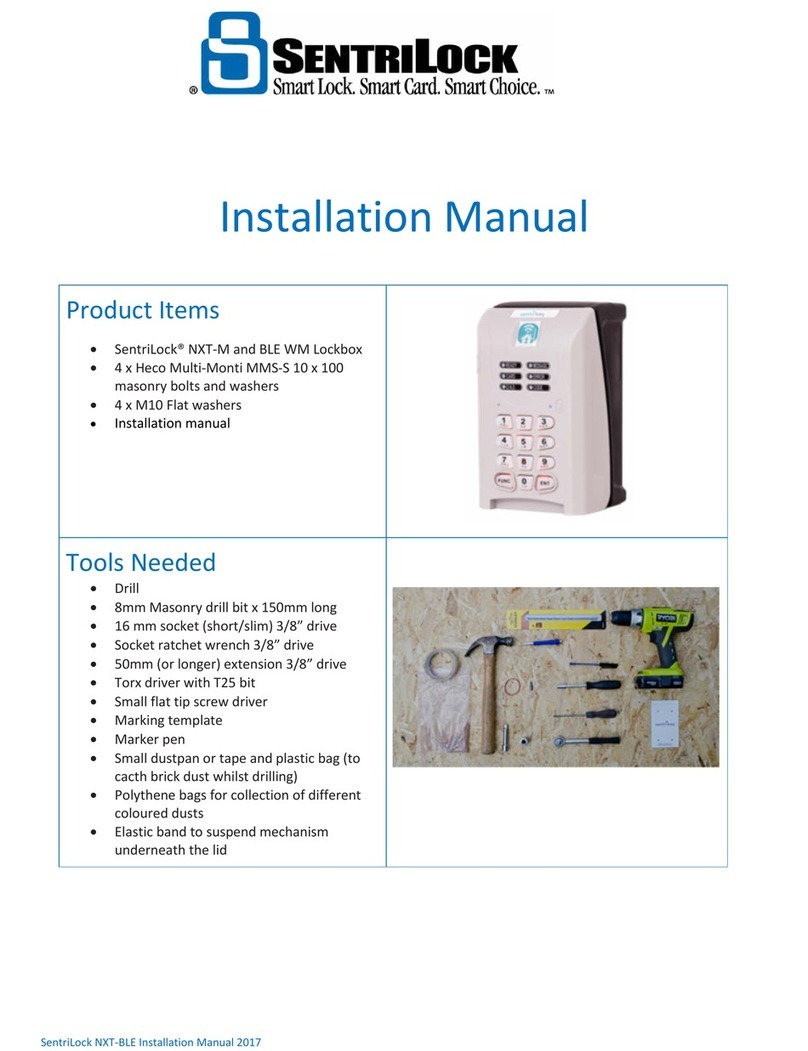
SentriLock® NXT-M and BLE WM Lockbox
4 x Mungo MBK-STB 10x80mm masonry
screws and nylon plugs (alternative fixings
can be used, please refer to the
substrate/fixings matrix on page 2)
Installation manual
Tools Needed
Drill
10mm Masonry drill bit
Torx driver with T40 bit
Torx driver with T25 bit
Small flat tip screw driver
Marking template
Marker pen
Small dustpan or tape and plastic bag (to
catch brick dust whilst drilling)
Polythene bags for collection of different
coloured dusts
Elastic band to suspend mechanism
underneath the lid

Installation Manual
SentriLock NXT-BLE Installation Manual – 2019 v3 Page 2 of 9
Before Starting
The SentriLock® NXT-M and BLE WM Lockboxes are designed to be mounted directly to a building or other secure
structure. The Lockboxes have been certified to Loss Prevention Standard (“LPS”) 1175, A10, B3 & C1 when mounted
using the following fasteners and substrates.
SUBSTRATE FASTENERS SECURITY RATING
Brickwork, concrete, stone 4 x Mungo MBK-STB 10 x 80mm masonry screws and
nylon plugs
A10, B3 & C1
Rendered substrate up to 20mm thick 4 x Mungo MBK-STB 10 x 100mm masonry screws
and nylon plugs
A10 & B3
Steel (minimum 4mm thick) 4 x M10 bolts (with tapped holes)
Or
4 x M10 bolts with M10 Security Shear Nuts
A10, B3 & C1
Mounting the lockboxes using any other mounting bolts or onto weaker wall structures will invalidate the security
rating.
It is important that the designated installer follows this instruction manual for the installation to retain the awarded LPS
certification. Should it be required to mount a lockbox on other than a conventional masonry wall, please contact
SentriLock to discuss suitability and the possible use of different specification mounting bolts.
This installation manual is a confidential document which is only issued to designated Installers. The purpose of this
manual is to act as a reference manual for the installation of a SentriLock® NXT-M and BLE WM Lockboxes. The
document remains the property of SentriLock, LLC.
Preparation
Position of Installation
It is recommended that the Lockbox be mounted in a position that makes attacks more difficult to reduce the
leverage an attacker can impart on the lockbox.
Surface
It is important that the mounting location is flat. If not, the pressure exerted by the mounting screws when
tightened will twist the Lockbox frame and may render it inoperable. Do not attempt to mount the lockbox on
any surface that is not flat.
On rendered walls ensure the use of Mungo MBK-STB 10x80mm masonry screws and nylon plugs as they will
maintain the LPS1175 A10 & B3 security rating.
Contact SentriLock to discuss suitability and the possible use of different mounting fasteners for non-standard
masonry surfaces.
Drilling the Mounting Holes into Brick Substrate
Where possible, all screws should fasten directly into the central part of a brick.
It is important the mounting holes are not in the mortar between bricks.
The drill holes must be at 90 degrees’ angle to the wall and to the specified depth.
Catch and save the dust from drilling to leave the area neat and tidy and to retain the dust for colouring filler
used to refill holes after de-installation.

Installation Manual
SentriLock NXT-BLE Installation Manual – 2019 v3 Page 3 of 9
Drilling the Mounting Holes into Steel Substrate
If drilling tapping holes into steel ensure that the thickness is not thinner than 4mm
The following advice is provided for tapping holes
o Start by drilling a hole enlarging to a diameter that will fit the M10 bolt
o Use tapping fluid to spray the hole
o Drill the hole using the tapping drill (one that is less than the fixing hole as it needs to engage within the
steelwork) making sure to keep the drill straight
o Pulsing the trigger of the drill, tap the hole a couple of threads and then reverse the drill back out of the
hole slightly before drilling forwards again. Continue to do this until you have gone through the steel
plate. Then carefully reverse the drill out of the hole.
If using the 4 x M10 bolts with M10 Security Shear Nuts, drill the hole to the correct diameter and attach the
security nuts to the back ensuring to tighten them until the hexagonal part shears off leaving a tamper proof
cone
Instructions
See SL30174 for detailed drilling template. (Page 9)
Step
Instructions
Picture
1 Open and Disassemble Lockbox
1.1
a) Open the lockbox using FUNC 3 ENT. [ENT wakes up the
Blue tooth].
b) Carefully note the interconnect cable routing and position
before proceeding. You will need to route the cable in exactly
this manner when
reassembling the unit later.
c) Remove the light grey Key Bin and set aside for re-
assembly
Lockboxes with mechanical door stops
Remove the two #6-32 X .250 LG. BUTTON HEAD, TORX (T1O)
screws located on the bottom of the lockbox that attach the
door rotation limiter. Save these parts for later reassembly.
1.2
On the keypad of the lockbox, hold the ENT key down until
you hear a beep from the lockbox and the keypad
illuminates. On the keypad, press FUNC FUNC 3 7 3 7 3
FUNC ENT. This will cause the unit to unlatch and leave the
latches in the retracted state. Leave the lockbox in the open
state while installing.

Installation Manual
SentriLock NXT-BLE Installation Manual – 2019 v3 Page 4 of 9
Step
Instructions
Picture
1.3
a)
Using a T25 Torx screw driver, remove the single center
fastener bolt that retains the metal Security Plate and
Latching Mechanism.
b)
Set aside for re-assembly.
1.4
a)
Carefully remove the metal Security Plate. Use a flat
blade screwdriver if necessary.
b)
Set aside for re-assembly.
1.5
Remove mechanism box from vault.
WARNING
Be extremely careful not to damage the interconnect cable or
the latch mechanism.
a)
Carefully pry the Latch Mechanism out of the vault by
lifting the bottom edge out first. Use a flat blade
screwdriver if necessary.
b)
Protect the Latch Mechanism and lay on the keypad lid.
c)
It is possible to suspend the mechanism on the
underside of the keypad by means of the elastic
band. This can ensure it is kept out of the way while
screwing the Lockbox to the wall

Installation Manual
SentriLock NXT-BLE Installation Manual – 2019 v3 Page 5 of 9
1.6
a)
Carefully remove the metal Spacer Plate. Use a flat blade
screwdriver if necessary.
b)
Set aside for re-assembly.
2 Marking and Drilling Holes
(or metal substrate installation please refer to page 3 - Drilling the Mounting Holes into Steel Substrate)
Step
Instructions
Picture
2.1
Using the supplied drill template, mark the 4 mounting hole
centers to be drilled onto the surface. (The drill hole
positions in the slots must be at the extreme top end of the
slots, centered some 84mm from the bottom holes.)
WARNING
This is important, otherwise installing the screws will foul the
casing.
See SentriLock
Drawing
SL30174
(Page 9)
2.2
Centre punch all four drill points to stop the drill wandering
during the initial drilling.
WARNINGS
Ensure there are no electrical or data cables, gas or water
pipes or other utilities behind the surface before drilling.
Do not drill the holes through the Lockbox.
Do not breathe in the dust created by drilling – it contains
silica which can cause lung disease. Wear respiratory
protection.
a) Drill the holes with an 10mm masonry drill bit to 90 mm
depth. The quality of the drilled hole is the critical factor.
Ensure the holes are drilled perpendicular to the fixing
plane and that they are sufficiently deep.
a. If using the 100mm screws, drill the holes to an
110mm depth
b) Use the small dustpan to catch the dust from the drilling
or tape a plastic back to the wall underneath where the
holes will be drilled to catch the brick dust.
c) Sweep brick dust into a polythene bag for use during
deinstallation when filling holes and coloring filler.

Installation Manual
SentriLock NXT-BLE Installation Manual – 2019 v3 Page 6 of 9
3 Installing the Screws
Step
Instructions
Picture
3.1
Insert the nylon plug into the holes and tap them in gently
using a hammer.
3.2
Using four screws, fix the Lockbox to the wall.
a)
Install the top two screws first by sliding the box up in the
slotted top holes to its highest position (to allow for easy
access to the bolt heads).
b)
Screw them down to within one turn of being tight, but
do not fully tighten at this stage.
3.3
c)
Let the lockbox drop down in the top slotted holes now,
and then install the bottom two screws. Tighten them
completely.
d)
Go back to the top screws and tighten them completely.
e)
Check that all four screws are tightened and firmly secure.
WARNING: It is imperative when tightening the screws that
the process has not deformed or twisted the vault box. The
installation surface must be flat.

Installation Manual
SentriLock NXT-BLE Installation Manual – 2019 v3 Page 7 of 9
4 Reassemble Lockbox
Step
Instructions
Picture
4.1
Reverse the disassembly process.
a) Re-insert the metal Space Plate, ensuring it sits flush and
level.
b) Re-insert the Latch Mechanism (if necessary, by pushing
the door latches in slightly to get them around the latch
supports. Use a small flat blade screwdriver to push the
latch in further, one side at a time.)
c) Re-install the metal Security Plate and the single centre
bolt that retains the mechanism box.
Torque this fastener to 40.32 kg/cm (35 in/lbs).
4.2
a)
Carefully redress the interconnect cable into the original
position. This step is critical as cable life can only be
maintained if the cable is replaced in its original location
and configuration. Ensure the protective braid has not
slipped down the interconnect cable. There is a notch in
the bottom of the latch mechanism and the key holder
for the cable to locate in.
b)
Re-install the grey Key Holder into the lid.

Installation Manual
SentriLock NXT-BLE Installation Manual – 2019 v3 Page 8 of 9
5 Verify Lockbox works properly
Step
Instructions
Picture
5.1
Check the following:
a)
Door latches move freely;
b)
Cable is properly routed such that it will not be pinched,
stretched or damaged when the Lockbox door is closed;
c)
Fastener bolt is tightened securely;
d)
Lockbox is not twisted
WARNING: Do not close the Lockbox door until latches are
extended (and so proving they move freely.) Failure to do so
may render the unit inoperable and require unit destruction!
Lockboxes with mechanical door stops
Reinstall the door rotation limiter utilizing the two screws as
shown.
5.2
To test the system, on the keypad of the lockbox, hold the
ENT key down until you hear a beep from the lockbox and
the keypad illuminates. On the keypad, press FUNC 3 ENT.
The latches should retract slightly the first time and then
return to the extended position. Test the unit with the door
in the open position until you are satisfied the latching
system is functioning properly.

Installation Manual
SentriLock NXT-BLE Installation Manual – 2019 v3 Page 9 of 9
Other manuals for NXT-M
1
This manual suits for next models
1
Table of contents
Other Sentrilock Lock manuals

Sentrilock
Sentrilock REALTOR RAD User manual

Sentrilock
Sentrilock GENI User manual

Sentrilock
Sentrilock Lockbox NXT Series User manual

Sentrilock
Sentrilock NXT-M User manual

Sentrilock
Sentrilock REALTOR NXT Series User manual

Sentrilock
Sentrilock REALTOR NXT/NXT User manual

Sentrilock
Sentrilock Bluetooth REALTOR Lockbox-EX User manual