Sherwin-Williams 3040 User manual

824120
Rev. C
OWNER’S MANUAL
Belt-Drive Pressure Washers
3040
Model 824121, Series A
3000 psi (21.0 MPa, 210 bar) Operating Pressure
3400 psi (23.4 MPa, 234 bar) Maximum Working Pressure
3235
Model 824122, Series A
3200 psi (22.1 MPa, 221 bar) Operating Pressure
3600 psi (24.8 MPa, 248 bar) Maximum Working Pressure
3540
Model 824123, Series A
3500 psi (24.1 MPa, 241 bar) Operating Pressure
3900 psi (26.9 MPa, 269 bar) Maximum Working Pressure
4043
Model 824124, Series A
4000 psi (27.6 MPa, 276 bar) Operating Pressure
4300 psi (29.6 MPa, 296 bar) Maximum Working Pressure
U.S. Patent
Patented 1983, Canada
Other Patents Pending
Related Manual
Hydra-CleanRGun 308511. . . . . . . . . . . . . . . . . . . . . . . .
The SHERWIN–WILLIAMS COMPANY, CLEVELAND, OHIO 44115
ECOPYRIGHT 1998, GRACO INC.
This manual contains important
warnings and information.
READ AND RETAIN FOR REFERENCE
04607
3040 Pressure Washer
Model 824121

2 824120
Table of Contents
Warnings 2. . . . . . . . . . . . . . . . . . . . . . . . . . . . . . . . . . . . . .
Setup 4. . . . . . . . . . . . . . . . . . . . . . . . . . . . . . . . . . . . . . . . .
Pressure Relief Procedure 5. . . . . . . . . . . . . . . . . . . . . . .
Operation 5. . . . . . . . . . . . . . . . . . . . . . . . . . . . . . . . . . . . .
Troubleshooting 8. . . . . . . . . . . . . . . . . . . . . . . . . . . . . . . .
Pump Service 10. . . . . . . . . . . . . . . . . . . . . . . . . . . . . . . . .
Parts Drawings and Lists
3040 and 3235 Pressure Washers 12. . . . . . . . . . . . .
Pump for 3040 and 3235 Pressure Washers 14. . . .
3540 Pressure Washer 16. . . . . . . . . . . . . . . . . . . . . . .
Pump for 3540 and 4043 Pressure Washers 18. . . .
4043 Pressure Washer 22. . . . . . . . . . . . . . . . . . . . . . .
Technical Data 27. . . . . . . . . . . . . . . . . . . . . . . . . . . . . . . .
Sherwin–Williams Standard Warranty 28. . . . . . . . . . . .
Phone Number 28. . . . . . . . . . . . . . . . . . . . . . . . . . . . . . . .
Symbols
Warning Symbol
WARNING
This symbol alerts you to the possibility of serious
injury or death if you do not follow the instructions.
Caution Symbol
CAUTION
This symbol alerts you to the possibility of damage to
or destruction of equipment if you do not follow the
instructions.
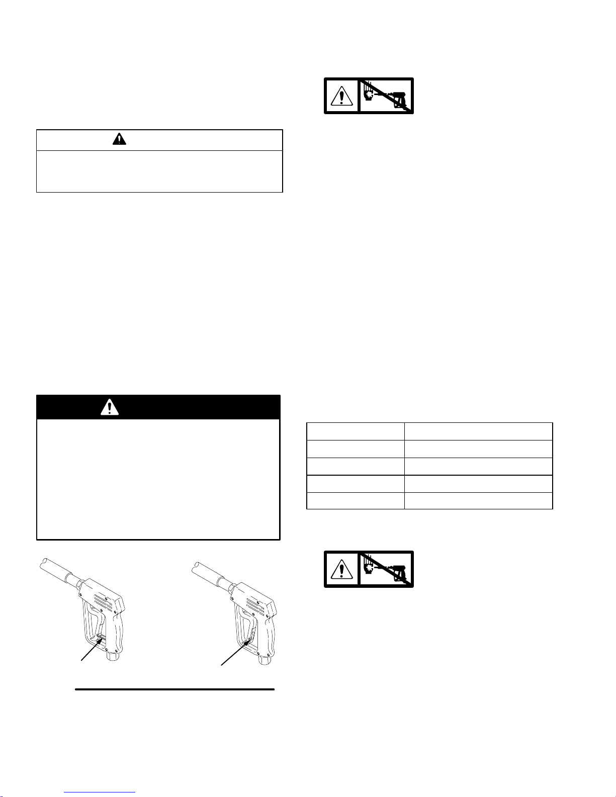
DDo not point gun at anyone or at any part of body.
DFluid injected into the skin might look like just a cut, but it is a serious injury. Get emergency
medical attention.
WARNING
WARNING
INJECTION HAZARD
Spray from the gun, leaks or ruptured components can inject fluid into your body and cause serious
injury. Fluid splashed in the eyes or on the skin can also cause serious injury.
DDo not stop or deflect leaks with hand, body, glove or rag.
DDo not put hand or fingers over spray tip.
DTighten fluid connections before starting equipment.
DEngage the gun trigger safety when you stop spraying.
DFollow Pressure Relief Procedure on page 5 if spray tip clogs and before cleaning, checking or
servicing equipment.
DRepair or replace worn or damaged parts immediately.
DCheck hoses, tubes, and coupling daily. Do not repair high-pressure couplings; replace entire
hose. Fluid hoses must have spring guards on both ends to prevent kinks and rupture.

824120 3
DDo not alter throttle setting.
WARNING
WARNING
MOVING PARTS HAZARD
Moving parts, such as the drive belt, can pinch or amputate fingers.
DKeep clear of moving parts when starting or operating equipment.
DDo not operate the pressure washer without all guards and interlocks installed and functioning.
HAZARDOUS FLUIDS
Improper handling of hazardous fluids can cause serious injury, even death, due to splashing in eyes,
ingestion or bodily contamination.
DKnow specific hazards of fluid being used.
DWear protective eye wear, gloves, clothing, and respirator as recommended by fluid and solvent
manufacturer.
DStore hazardous fluids in approved containers. Dispose of hazardous fluids per local, state and
national guidelines.
FUEL HAZARD
The fuel used in this pressure washer is combustible. When spilled on a hot surface, it can ignite and
cause a fire.
Do not fill the fuel tank while the engine is running or hot.
EQUIPMENT MISUSE HAZARD
Misuse of the pressure washer or accessories can cause them to rupture and result in fluid injection,
splashing in the eyes or on the skin, or other serious injury.
DDo not alter or modify any part or factory-set adjustment of this equipment.
DDo not exceed the maximum working pressure of any component or accessory in the system.
DDo not use any chemicals that are incompatible with the wetted parts as stated in Technical
Data on page 27.
EXHAUST HAZARD
The exhaust contains poisonous carbon monoxide, which is colorless and odorless.
Do not operate this equipment in a closed building.

4 824120
Setup
04610
04607
high-pressure hose
connection hose
rack
inlet water
connection
3/4”garden
hose
gun
hose
Check for Shipping Damage
Check the pressure washer for shipping damage. If
anything is damaged, notify the carrier immediately.
Connect High-Pressure Hose and Gun
Connect the high-pressure hose between the pump
outlet and the gun inlet. Both of these connections are
made with quick couplers.
CAUTION
Up to 100 ft (30 m) of high-pressure hose may
be used. Longer hoses could affect pressure washer
and chemical injector performance.
Install Spray Tip
Install the appropriate spray tip on the wand. See
Installing and Changing Spray Tips on page 6. If
you are using a sandblaster kit, see its separate manu-
al for installation instructions.
Connect to Water Supply
CAUTION
Before you connect the garden hose to the pressure
washer, check your local plumbing code regarding
cross-connection to the water supply. Backflow
Preventer 801133 is available to prevent backflow of
contaminated water into the fresh water supply.
Install it upstream from the pump.
If inlet water pressure is over 60 psi (4.1 bar) Regu-
lating Water Valve 800258 must be installed at the
garden hose connection.
Do not exceed 160_F (70_C) inlet water tempera-
ture.
Connect a hose with at least a 3/4-in. (19 mm) ID from
the water supply to the 3/4-in. garden hose inlet. The
supply hose should not be more than 50 ft (15 m) long
NOTE: The water source must have a minimum flow
rate equal to that of the pressure washer. See Techni-
cal Data on page 27.

824120 5
Pressure Relief Procedure
INJECTION HAZARD
The system pressure must be manually
relieved to prevent the system from
starting or spraying accidentally. Fluid
under high pressure can be injected through the
skin and cause serious injury. To reduce the risk of
injury from injection, splashing fluid, or moving
parts, follow the Pressure Relief Procedure
whenever you
DAre instructed to relieve the pressure
DStop spraying for more than 10 minutes
DCheck or service any of the system equipment
DInstall or clean the spray nozzle
WARNING 1. Engage the trigger safety latch.
2. Turn the pressure washer off, and remove the
ignition cable from the spark plug..
3. Shut off the water supply.
4. Disengage the trigger safety latch, and trigger the
gun to relieve pressure. Then engage the trigger
safety latch.
If you suspect that the spray tip or hose is clogged or
that pressure has not been fully relieved after following
the steps above: Disengage the trigger safety latch,
and trigger the gun to relieve pressure. Wrap a rag
around the hose end coupling, and VERY SLOWLY
loosen the coupling to relieve pressure gradually. Then
loosen it completely. Then clear the tip or hose.
Operation
Startup
Always use this startup procedure to ensure that the
pressure washer is started safely and properly.
DAlways engage the gun trigger safety latch when
you stop spraying even for a moment. This reduces
the risk of fluid injection or splashing in the eyes or
on the skin if the gun is bumped or triggered acci-
dentally.
DAlways observe the CAUTIONS in this section to
avoid costly damage to the pressure washer.
DIf you use the Sandblaster Kit, see the Sandblaster
Kit manual for detailed cleaning information.
1. Check the oil level.
NOTE: All pressure washers are equipped with a
low-oil sensor that shuts the engine off if the oil level
falls below a certain level. If the engine stops unex-
pectedly, check the oil and the fuel levels. Check the
oil level each time you add fuel.
2. Check fuel level.
WARNING
FIRE HAZARD
Do not refuel a hot engine. Refueling a
hot engine could cause a fire. Use only
fresh, clean, regular or unleaded gasoline. Close
the fuel shutoff valve during refueling.
3. Turn on the water supply.
CAUTION
Never run the pressure washer without water. Costly
damage to the pump will result. Always be sure the
water supply is completely turned on before you run
the pressure washer.
4. Trigger the gun until water sprays from the tip
indicating that the air is purged from the system.
5. Open the fuel shutoff valve. Be sure the spark plug
ignition cable is pushed firmly onto the spark plug.
Put the engine switch in the ON position, and put
the throttle in the RUN position.
CAUTION
Do not allow the pressure washer to idle for more
than 10 minutes. Doing so could cause the
recirculating water to overheat and seriously
damage the pump. Turn off the pressure washer if
it will not be spraying at least every 10 minutes. If
heated inlet water is used, reduce this time more.
Do not operate the pressure washer with the inlet
water screen removed. This screen helps keep
abrasive sediment, which could clog the pump or
damage the pump cylinders, out of the pump. Keep
this screen clean. Do not pump caustic materials;
such materials could corrode the pump
components.
6 824120
Operation
6. Start the engine with the electric starter
(3540 and 4043), or pull the starter rope. If you
use the starter rope to start the engine, brace one
foot on the pressure washer cart, and pull the
starter rope out quickly.
CAUTION
Do not allow the starter rope to snap back against
the engine. Let the rope recoil gently to prevent
damage to the recoil mechanism.
NOTE: For easier starting, have one person start
the pressure washer while another person triggers
the gun.
If the engine is cold, start the engine with the
choke completely closed. In cool weather, you
might have to let the engine run with the choke
closed for the first 10 to 30 seconds. In warm
weather, open the choke completely as soon as
the engine starts.
If the engine is warm, start the engine with the
choke completely open or partially closed. When
the engine starts, open the choke completely.
Trigger Safety Latch
WARNING
To reduce the risk of serious bodily injury, including
fluid injection or splashing in the eyes or on the
skin, always engage the trigger safety latch when
you stop spraying even for a moment. In the
engaged position, the trigger safety latch prevents
the gun from being triggered accidentally by hand
or if it is dropped or bumped. Be sure the latch is
pushed fully down, or it will not prevent the gun
from being triggered. See Fig. 1.
04612
engaged disengaged
Trigger Safety Latch
Fig. 1
Chemical Injector Operation
1. Relieve the pressure.
See page 5.
2. Insert the chemical filter (attached with clear tubing
to the chemical injector) into the container of
chemical.
3. Install the black large-orifice chemical tip. See
Installing and Changing Spray Tips below.
The large orifice of the chemical tip causes a drop in
pressure that actuates the chemical injector. Changing
back to a small-orifice spray tip deactivates the chemi-
cal injector and produces high pressure for rinsing. The
chemical filter can be left in the chemical container
during high-pressure use. To regulate the flow rate of
the chemical, turn the chemical adjustment knob on
the injector. Maximum chemical flow is a full two turns
counterclockwise from the CLOSED (clockwise) posi-
tion.
Installing and Changing Spray Tips
Spray tips have 4- or 5-digit numbers on them. The
first two digits are the spray angle. Select the spray tip
appropriate for your application. Tip holding holes are
provided on the chassis.
Spray Tip Number Spray Pattern Fan Angle
00XXX 0_blaster (red)
15XXX 15_(yellow)
25XXX 25_(green)
40XXX 40_(white)
NOTE: The chemical injector tip is brass and has a
large opening and a black plastic cap.
1. Relieve the pressure.
See page 5.
2. Point the gun and wand away from yourself and
anyone else.
3. Without holding your hand over the spray tip (A),
pull back the quick coupler ring (B). Remove the
current tip and/or install a different one. Then push
back the ring. See Fig. 2.
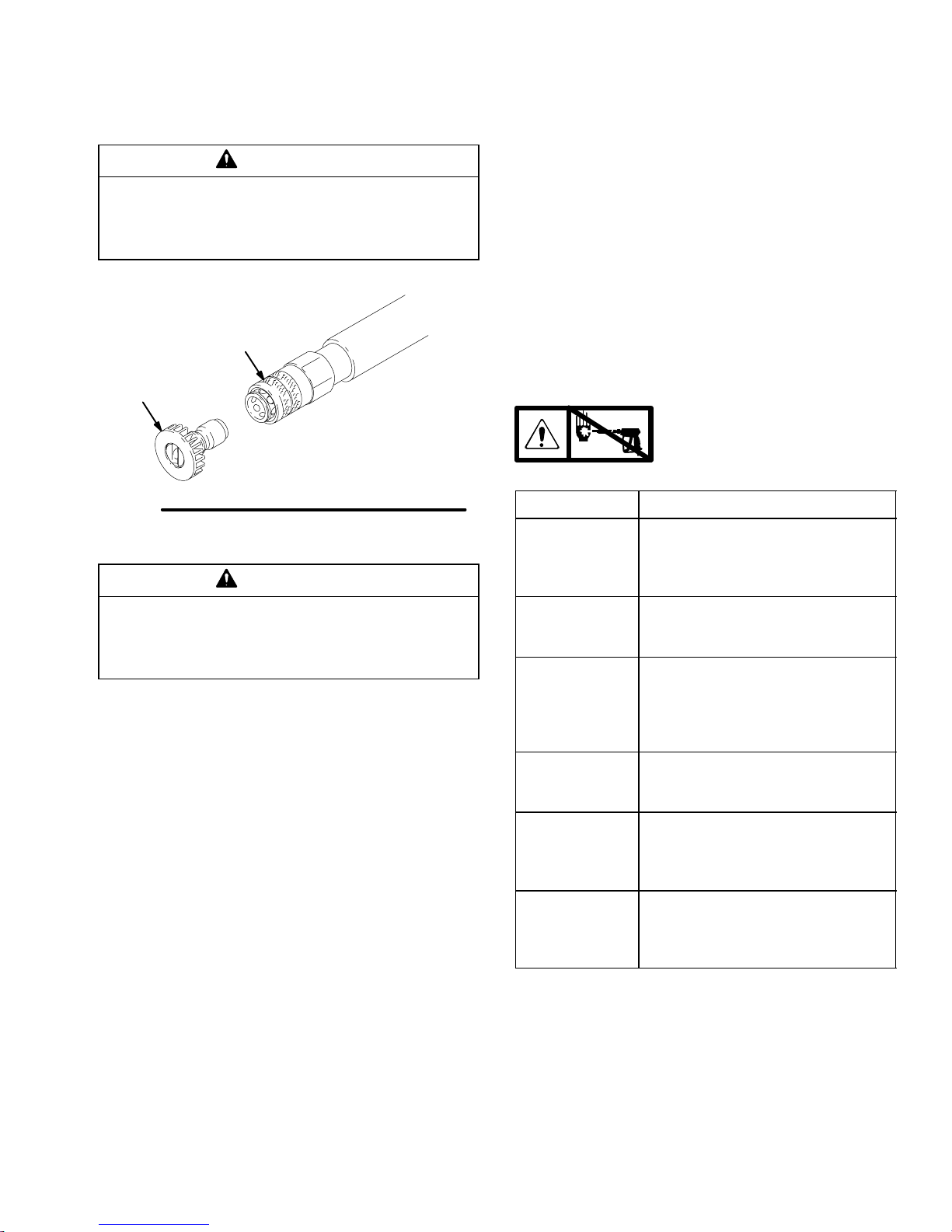
824120 7
Operation
4. Pull on the tip to be sure it is secure before you
spray again.
CAUTION
To avoid blowing the O-ring out of the quick coupler
due to the high pressure in the system, never
operate the pressure washer without a tip securely
mounted in the quick coupler.
04929
A
B
Fig. 2
Shutdown, Flushing, and Storage
CAUTION
If water freezes in the pressure washer, thaw it in a
warm room before you try to start it. Do not pour
hot water on or into the pump; it could crack the
ceramic plungers.
DIf the pressure washer will be exposed to freezing
temperatures, drain all water out of the pump. If it
must be stored in freezing temperatures, flush it
with a 50% antifreeze solution, and relieve the
pressure. Flush the pressure washer before you
use it again to remove the antifreeze.
DBefore you store the pressure washer overnight or
transport it, disconnect the water supply, and turn
off the fuel supply valve.
DAfter each use, wipe all surfaces of the pressure
washer with a clean, damp cloth.
DPerform the appropriate maintenance. See Mainte-
nance Chart at right.
Maintenance
Observing regular maintenance intervals helps ensure
that you get maximum performance and life from the
pressure washer.
There is a break-in period for the engine and pump.
After you change the oil in these components following
their respective break-in periods, the interval between
required changes is longer.
If the pressure washer is operated in dusty conditions,
these maintenance checks should be made more
often.
Maintenance Chart
Relieve the pressure
(see page 5) before you
proceed with maintenance.
Interval What to do
Daily Clean water inlet screen and filter.
Check engine and pump oil levels.
Fill as necessary. Check gasoline
level. Fill as necessary.
After first
5 hours of
operation
Change engine break-in oil. Drain
oil when warm. Use SAE 30 or
10W–30 detergent oil.
After every
25 hours of
operation
Clean and remove air cleaner
foam. Wash with water and
detergent. Dry thoroughly. Rub
with oil, and squeeze to distribute
oil.
After first
50 hours of
operation
Change pump break-in oil. Use
SAE 20 or 30 non-detergent oil.
After every
100 hours of
operation, or
every 3 months
Clean or replace paper air cleaner
cartridge. Tap gently to remove
dirt. Change engine oil. Use SAE
30 or 10W–30 detergent oil.
After every
500 hours of
operation, or
every 6 months
Change pump oil. Use SAE 20 or
30 non-detergent oil.

8 824120
Troubleshooting
Relieve the pressure (see page 5) before you proceed with troubleshooting.
PROBLEM CAUSE SOLUTION
Engine not starting or
hard to start No gasoline in fuel tank or carburetor
Low oil
Start/Stop switch in STOP position
Water in fuel, or old fuel
Engine flooded or improperly choked
Dirty air cleaner filter
Spark plug dirty, wrong gap, or wrong type
Gun not triggered
Fill the tank with gasoline, and open fuel shut off valve.
Check fuel line and carburetor.
Add oil to proper level.
Move switch to START position.
Drain fuel tank and carburetor. Use new fuel, and make
sure dry spark plug is dry.
Open choke, and crank engine several times to clear
out gas. Make sure spark plug is dry.
Remove and clean.
Clean, adjust the gap, or replace.
Trigger gun while starting engine.
Engine missing or
lacking power Partially plugged air cleaner filter
Spark plug dirty, wrong gap, or wrong type Remove and clean.
Clean, adjust the gap, or replace.
Pressure too low
and/or pump running
roughly
Worn or wrong size tip
Inlet filter clogged
Worn packings, abrasives in water, or
natural wear
Inadequate water supply
Belts slipping
Fouled or dirty inlet or discharge valves
Restricted inlet
Worn inlet or discharge valves
Leaking high-pressure hose
Replace with tip of proper size.
Clean. Check more frequently.
Check filter. Replace packings. See Pump Service on
page 10.
Check water flow rate to pump.
Tighten or replace; use correct belts, and replace both
at same time.
Clean inlet and discharge valve assemblies. Check filter.
Check if garden hose is collapsed or kinked.
Replace worn valves. See Pump Service on page 10.
Replace high-pressure hose.
Water leaking from un-
der pump manifold Worn packings Install new packings. See Pump Service on page 10.
Water in pump oil Humid air condensing inside crankcase
Worn packings
Oil seals leaking
Change oil as specified in Maintenance on page 7.
Install new packings. See Pump Service on page 10.
Install new oil seals. See Pump Service on page 10.
Packings failing fre-
quently or prematurely. Scored, damaged, or worn plungers
Abrasive material in the fluid being
pumped
Inlet water temperature too high
Overpressurizing pump
Excessive pressure due to partially
plugged or damaged tip
Pump running too long without spraying
Running pump dry
Install new plungers. See Pump Service on page 10.
Install proper filtration on pump inlet plumbing.
Check water temperature. It should not exceed
160_F (70_C).
Do not modify any factory-set adjustments. See EQUIP-
MENT MISUSE HAZARD on page 3.
Clean or replace tip. See Installing and Changing
Spray Tips on page 6.
Never run pump more than 10 minutes without spraying.
Do not run pump without water.
Strong surging at inlet,
and low pressure on
discharge side
Foreign particles in the inlet or discharge
valve, or worn inlet and/or discharge
valves
Clean or replace valves. See Pump Service on
page 10.

824120 9
Notes
10 824120
Pump Service
Repair kits are available. See Pump Repair Kits for 3040 and 3235 Pressure Washers on page 15. See Pump
Repair Kits for 3540 and 4043 Pressure Washers on page 20. For the best results, use all parts in the kits.
Relieve the pressure
(see page 5 ) before you
proceed with service.
NOTES:
DThe following metric wrenches are needed:
10 mm, 13 mm, and 30 mm.
DThere are two tool kits to aid in servicing the pump.
Kit 800298 is used to ease installation of packings.
Kit 800271 includes the items in 800298 and tools
to aid in the removal of packing retainers.
Valves
NOTE: For a set of six valves, order Valve Assembly
Kit 801472.
1. Remove the hex plug from the manifold using a
30 mm wrench.
2. Examine the O-ring under the hex plug, and re-
place if cut or distorted.
3. Remove the valve assembly from the cavity; the
assembly might come apart.
4. Install the new valve. Install the O-ring and hex
plug; torque to 75 ft-lb (103 NSm).
NOTE: Retorque the plug after 5 hours of operation.
Pumping Section
1. Remove the eight capscrews and lockwashers
from the manifold using a 13 mm wrench.
2. Carefully separate the manifold from the crank-
case.
NOTE: You might have to tap the manifold lightly with
a soft mallet to loosen it.
CAUTION
To avoid damage to the plunger or seals, keep the
manifold properly aligned with the ceramic plungers
when you remove it.
3. Carefully examine each plunger for any scoring or
cracking, and replace as necessary.
Servicing the Plungers
NOTE: Plunger Repair Kits 801474 (for 3040 and
3235) and 803510 (for 3540 and 4043) are available to
replace retainers, O-rings, washers, and backup rings
for three cylinders.
1. Loosen the plunger retaining screw five to six turns
using a 10 mm wrench. Push the plunger towards
the crankcase to separate the plunger and retain-
ing screw.
2. Remove the screw from the plunger, and examine
the O-ring, backup ring, and copper bearing/gasket
washer. Replace these parts if necessary.
3. Remove the plunger and flinger from the plunger
shaft. Clean and replace parts as necessary.
4. Inspect the plunger shaft for oil leakage from the
crankcase. If leaking is obvious, replace the oil
seals. Otherwise, DO NOT remove these seals
because they cannot be reused. Oil Seal Kit
801473 is available for replacing the seals.
5. Lightly grease the flinger (and the oil seal if it is
being replaced), and replace on the plunger shaft.
Then install the plunger.

824120 11
Pump Service
6. Lightly grease the retaining screw and the outer
end of the plunger. Place the washer, O-ring, and
backup ring around the screw, and install the
screw through the plunger. Torque to 14.4 ft-lb
(19.5 NSm).
NOTE: If you plan to replace the packings, see Serv-
icing the V-Packings.
7. Lubricate the outside of each plunger. Slide the
manifold onto the crankcase, being careful not to
damage the seals.
8. Install the capscrews and washers finger tight.
Torque the screws to 21.7 ft-lb (29 NSm) following
the tightening pattern shown in Fig. 3. Uneven
tightening might cause the manifold to bind or jam.
14
2
3
5
8
7
6
Fig. 3
Servicing the V-Packings
NOTE: There are two types of packing kits for each
pressure washer:
For 3040 and 3235:
801486 contains packings only.
801487 contains packings, rings, and retainers.
For 3540 and 4043:
803511 contains packings only.
803512 contains packings, rings, and retainers.
1. Remove the manifold as outlined in the Pumping
Section.
2. Carefully pull the packing retainer from the mani-
fold. Examine the O-ring, and replace if cut or
damaged.
3. Remove the V-packing and head ring. Pull out the
intermediate retainer ring. Remove the second
V-packing and second head ring.
4. Inspect all parts and replace as necessary.
5. Thoroughly clean the packing cavities, and exam-
ine for debris or damage.
6. Lightly grease the packing cavities, and replace
the packings in the following order: head ring,
V-packing, intermediate ring, head ring, V-packing,
packing retainer. Install the O-ring in the retainer
groove.
CAUTION
Install the parts in the proper order and facing the
proper direction. Improperly installed parts will
cause a malfunction.
7. Reassemble the manifold as instructed in Servic-
ing the Plungers.
1
23c
34 84
19
67
51
18f
36
23b
84
83
67 43 44
5
39
55
42
45
46
47
49
41
28
11
18a 12
13
15
14
84
85
84
55
74
84
55
15
86
2
22 9
84 286
25
984
10
18e
18g
18b
18d
18c
18
18h
23
23a
1e
1f
1d
1c
1b
1a
29
30
31
32
17
38 37
48
67 6
67
26
04604
33
94
95
69
21 87 93 73 74
70
79
78
7776 80
81
82
88
89
71
55
96
12 824120
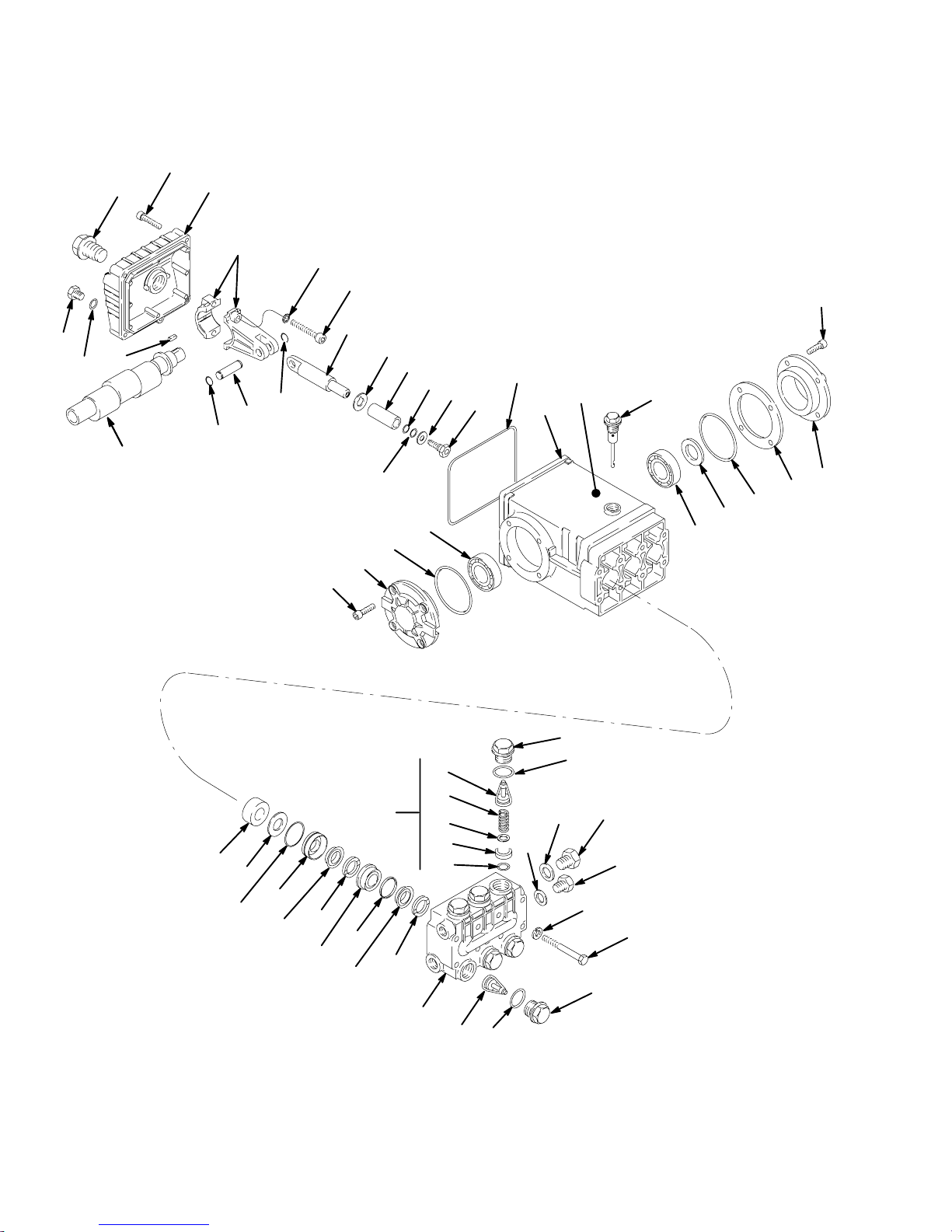
Parts: 3040 and 3235 Pressure Washers
Model 824121, Series A: 3040 Pressure Washer
Model 824122, Series A: 3235 Pressure Washer

824120 13
Parts: 3040 and 3235 Pressure Washers
Model 824121, Series A: 3040 Pressure Washer
Model 824122, Series A: 3235 Pressure Washer
Ref.
No. Part No. Description Qty. Ref.
No. Part No. Description Qty.
1 800392 GUN and WAND ASSEMBLY
(includes 1a to 1f) 1
1a 803350 GUN (See manual 308511) 1
1b 801134 WAND 1
1c 801674 SLEEVE 1
1d 801009 QUICK COUPLER, female; 1/4 1
1e 801603 NIPPLE 1
1f 801569 QUICK COUPLER, female; 3/8 1
2 100023 WASHER, flat; 3/8 4
4 801539 BUMPER 1
5 803926 BELT GUARD 1
6 803534 LABEL, ID 1
7 800676 CHASSIS 1
9 100214 WASHER, lock; 5/16 3
10 801550 WHEEL, pneumatic 2
11 801612 WASHER, flat; 1/2 2
12 801020 NUT, lock; 1/2–13 2
13 801556 AXLE 1
14 800678 BRACKET, rail stiffener 1
15 801546 SCREW, cap, hex hd;
3/8–16 x 1–1/4 4
17 LABEL, ID
803161 3040 Pressure Washer 1
803904 3235 Pressure Washer 1
18 800160 FRONT LEG ASSEMBLY
(includes 18a to 18h)
18a 801537 LEG, front 1
18b 801506 BOOT 1
18c 801593 SPRING 1
18d 801505 RETAINER, spring 1
18e 801504 BUMPER, rubber 1
18f 801531 SCREW, cap, hex hd; 3/8–16 x 7 1
18g 100132 WASHER, flat 1
18h 101566 NUT, lock; 3/8–16 1
19 803925 HANDLE 1
21 804498 QUICK COUPLER, male; 3/8 1
22 803298 SCREW, cap, hex hd;
5/16–18 x 3–1/2 1
23 800375 HOSE ASSEMBLY
(includes 23a to 23c)
23a 804427 HOSE, high pressure; 3/8 x 50’1. . .
23b 804498 QUICK COUPLER, male; 3/8 1
23c 801569 QUICK COUPLER, female; 3/8 1
25 802016 BRACKET, rail stiffener 1
26 804500 LABEL, warning 1
28 801012 GROMMET, rubber 5
29 to 32 TIP ASSEMBLIES
3040 Pressure Washer
29 805547 0_(red), blasting, 00045 1
30 805548 15_(yellow), 15045 1
31 805549 25_(green), 25045 1
32 805550 40_(white), 40045 1
3235 Pressure Washer
29 805543 0_(red), blasting, 0004 1
30 805544 15_(yellow), 1504 1
31 805545 25_(green), 2504 1
32 805546 40_(white), 4004 1
33 805634 TIP ASSY (chemical injector) 1
34 803737 PUMP (see page 14) 1
36 802127 SCREW, cap, hex hd;
5/16–18 x 1–3/4 4
37 802363 LABEL, caution 1
38 290013 LABEL, warning 1
39 803158 ENGINE, 11 hp,HondatOHV 1
41 804356 BUMPER, rubber 1
42 804376 SCREW, cap, hex hd
5/16–18 x 3/8 1
43 801285 BELT, drive 2
44 801898 HUB, engine 1
45 SHEAVE, engine
803941 3040 Pressure Washer 1
801911 3235 Pressure Washer 1
46 801135 HUB, pump 1
47 803390 SHEAVE, pump 1
48 804495 LABEL, warning 1
49 803531 PLATE, back 1
51 801522 SCREW, cap, hex hd;
5/16–18 x 6–1/2 2
55 111040 NUT, lock; 5/16–18 13
67 110963 SCREW, flange, hex hd
5/16–18 x 3/4 5
69 801526 BRACKET, pump 2
70 156849 NIPPLE 1
71 UNLOADER ASSEMBLIES 1
800324 3040 Pressure Washer (3000 psi) 1
800325 3235 Pressure Washer (3200 psi) 1
73 803142 NIPPLE 1
74 803141 BYPASS HOSE 1
76 801111 NUT, garden hose 1
77 801110 ADAPTER, garden hose 1
78 804051 FILTER 1
79 402278 PLUG, plastic 1
80 801622 TEE 1
81 801523 NIPPLE 1
82 800115 VALVE, thermal relief 1
83 804382 BUSHING 4
84 100527 WASHER, flat; 5/16 20
85 100450 BOLT, hex hd; 5/16 x 18 x 1.0 4
86 100133 WASHER, lock; 3/8 4
87* 804388 CHEMICAL INJECTOR 1
88 804275 TUBE, chemical injector 1
89 801683 STRAINER, chemical injector 1
93 162024 COUPLING 1
94 802304 WASHER, lock 4
95 802305 SCREW, cap, socket head 4
96 801137 KEY, square 1
*Chemical Injector Repair Kit 244351.
NOTE: Chemical Injector Repair Kit 244351 is differ-
ent from Chemical Injector Repair Kit 244350.
19
12
12 13 14
20
18
39
40
14
15 41
21
23
22 24
32
33
26
28
27
29
25 3435 36 38
37
31
31
30
10
9
8
7
6
5
4
53
54
51
52
3
2
11 9
10
11
45
44
47
46
45
44
43
42
16
17
104608
22
15
56
14 824120
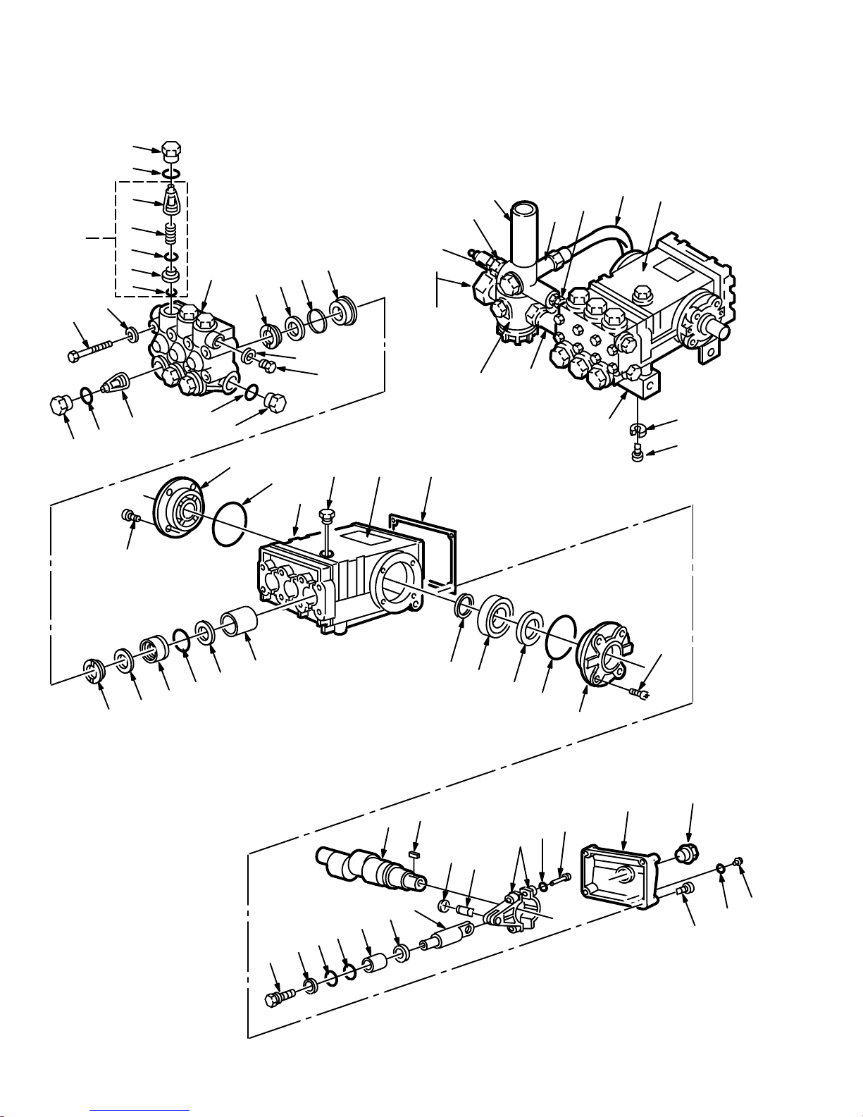
Parts: Pump for 3040 and 3235 Pressure Washers
Pump Model 803737, Series A

824120 15
Parts: Pump for 3040 and 3235 Pressure Washers
Pump Model 803737, Series A
Ref.
No. Part No. Description Qty. Ref.
No. Part No. Description Qty.
1 801467 MANIFOLD 1
2 801468 SCREW, cap, hex hd 8
3 801469 WASHER, lock 8
4 KIT 1 O-RING
5 KIT 1 SEAT, valve
6 KIT 1 PLATE, valve
7 KIT 1 SPRING
8 KIT 1 GUIDE, valve
9 KIT 4 O-RING
10 KIT 4 CAP
11 KIT 1 VALVE ASSEMBLY (includes 4 to 8)
12 803283 SCREW, cap, socket hd 8
13 803284 COVER, crankcase 1
14 802500 O-RING, crankcase cover 2
15 803285 BEARING, tapered roller 2
16 KIT 2 SEAL, oil
17 803286 BUSHING, piston 1
18 802895 CRANKCASE 1
19 801475 DIPSTICK 1
20 803144 GASKET, cover 1
21 803332 CRANKSHAFT 1
22 803288 RING, retaining 6
23 802794 KEY 1
24 803289 PIN, wrist 3
25 803290 GUIDE, piston 3
26 803291 ROD, connecting 1
27 803292 SCREW, cap, socket hd 5
28 803293 COVER, crankcase 1
29 802345 GAUGE, sight 1
30 802793 PLUG, oil drain 1
31 KIT 6 O-RING
32 803294 SCREW, cap, socket hd 6
33 801652 WASHER, lock 6
34 801660 WASHER, flinger 3
and KIT 6
35 801490 PLUNGER, ceramic 3
36 KIT 6 RING, backup
37 KIT 6 WASHER
38 KIT 6 SCREW, piston
39 803295 COVER, crankcase 1
40 803296 SHIM 2
41 KIT 3 SEAL, oil
42 KIT 28 O-RING
43 KIT 28 RETAINER, packing
44 KIT 8, 28 PACKING
45 KIT 28 RING, head
46 KIT 28 RETAINER, packing
47 KIT 28 RING, long life
48 801526 BRACKET, pump 2
49 802305 SCREW, cap, socket hd 2
50 802304 WASHER, lock 2
51 801482 PLUG, hex 1
52 801483 WASHER, flat 1
53 801484 PLUG, hex 1
54 801485 WASHER, flat 1
56 803083 LABEL, prevent freezing 1
Pump Repair Kits for 3040 and 3235 Pressure Washers
Kit
No. Repair Kit
Part No. Ref.
No. Description Qty
1801472
Valve
Assembly
11
4
5
6
7
8
VALVE ASSEMBLY
(includes 4 to 8)
O-RING
SEAT, valve
PLATE, valve
SPRING
GUIDE, valve
6
6
6
6
6
6
2801473
Oil Seal 16 SEAL, oil 3
3802511
Crankshaft
Seal
41 SEAL, oil 2
4802306
Valve
Cap
9
10 O-RING
CAP 6
6
Kit
No. Repair Kit
Part No. Ref.
No. Description Qty
6801474
Plunger
Repair
31
34
36
37
38
O-RING
WASHER, flinger
RING, backup
WASHER
SCREW, piston
3
3
3
3
3
8801486
Packing 44 PACKING 6
28 801487
Packing
and
Retainer
42
43
44
45
46
47
O-RING
RETAINER, packing
PACKING
RING, head
RETAINER, packing
RING, long life
1
1
2
1
1
1

67
68
43
69
26
42
41
44
75
66
63
5
63
5
76
48
45
5
47
82
80
81
83
84
79
5
78
21
24
125
56
12
5
2
25 17
13 14
16
5
23
31
33
34
35
36
29
2
528
20 19 18
51
32
30
77
90
39
77
46
12
248
50
49
456
62
37
37
5758 52
53
61
60
9
58
5756
59 55
54
11
10
8
64
15
76 77
87
88
87
86
85
77
3
38
27
65
40
87
26
42
69
92
Model 824123, Series A
16 824120
Parts: 3540 Pressure Washer

824120 17
Parts: 3540 Pressure Washer
Model 824123, Series A
Ref.
No. Part No. Description Qty. Ref.
No. Part No. Description Qty.
1 100188 NUT, hex; 5/16–18 11
2 100214 WASHER, lock; 5/16 13
3 803945 BELT, drive 1
4 803800 SHEAVE, engine 1
5 100023 WASHER, flat; 5/16 26
6 100450 SCREW, cap, hex hd;
5/16–18 x 1 9
8 803926 BELT GUARD 1
9 803525 BOLT, battery 1
10 804282 BRACKET, battery 1
11 801972 PAD, battery 1
12 801550 WHEEL and TIRE ASSEMBLY 2
13 801612 WASHER, flat; 1/2 2
14 801020 NUT, lock; 1/2–13 2
15 800676 CHASSIS 1
16 801556 AXLE 1
17 800678 BRACKET, rail stiffener 1
18 801546 SCREW, cap, hex hd;
3/8–16 x 1–1/4 4
19 100133 WASHER, lock; 3/8 1
20 100132 WASHER, flat; 3/8 4
21 800160 FRONT LEG ASSEMBLY
(includes 5, 78 to 84) 4
23 111040 NUT, lock; 5/16–18 4
24 803925 HANDLE 1
25 803298 SCREW, cap, hex hd;
5/16–18 x 3–1/2 1
26 156082 O-RING, quick coupler; 3/8 2
27 154594 O-RING, quick coupler; 1/4 1
28 802016 BRACKET, rail stiffener 1
29 801522 SCREW, cap, hex hd 2
30 804500 LABEL, chassis 1
31 801012 GROMMET, rubber 5
33 805547 0_(red), blasting, 00045 1
34 805548 15_(yellow), 15045 1
35 805549 25_(green), 25045 1
36 805550 40_(white), 40045 1
37 803967 ENGINE, 13 HP, Honda OHV 1
38 803508 PUMP ASSY (see page 18) 1
41 804427 HOSE, high pressure 3/8 x 50’1
42 801569 QUICK COUPLER, female; 3/8
(includes 26) 2
43 804498 QUICK COUPLER, male; 3/8 2
44 800392 GUN and WAND ASSEMBLY
(includes 42, 65, 66, 67, 68, 69) 1
45 803526 SPACER 1
46 801217 BUMPER, rubber 1
47 804495 LABEL, belt guard 1
48 801559 SCREW, cap, hex hd 1
49 803942 SHEAVE, pump 1
50 801898 HUB, engine 1
51 801135 HUB, pump 1
52 801959 TERMINAL PROTECTOR, black 1
53 801945 CABLE, battery; 12”long 1
54 803077 LABEL, battery 1
55 801954 BATTERY; 12V, 30 Amp 1
56 100527 WASHER, flat; 1/4 2
57 100016 WASHER, lock; 1/4 4
58 100015 NUT, hex; 1/4–20 4
59 801964 BOLT, carriage; 1/4–20 x 1 2
60 801946 CABLE, battery; 24”long 1
61 801958 TERMINAL PROTECTOR, red 1
62 803531 BASEPLATE, belt guard 1
63 801022 SCREW, cap, hex hd;
5/16–18 x 3/4 4
64 107069 BRACKET, battery 1
65 801009 QUICK COUPLER, female; 1/4
(includes 27) 1
66 801134 WAND, 32”1
67 801674 SLEEVE, 28”1
68 803350 GUN (See manual 308511) 1
69 156849 NIPPLE, hex; 3/8 1
75 800375 HOSE ASSEMBLY W/QUICK
COUPLERS (includes 41, 42, 43) 1
76 802363 LABEL, caution 1
77 290013 LABEL, warning 1
78 801531 SCREW, cap, hex hd; 3/8–16 x 7 1
79 801504 BUMPER, rubber 1
80 801505 RETAINER, spring 1
81 801593 SPRING 1
82 801506 BOOT 1
83 801537 LEG, front 1
84 801499 NUT, lock; 3/8–16 1
91 802025 TANK, fuel 1
92 801137 KEY, square 1
18 824120
Parts: Pump for 3540 and 4043 Pressure Washers
Pump Model 803508, Series A
65
67
66
64
63 55
50
49
48
57
58
59
60
61
62
46
47
44
45
10
9
8
7
6
5
41
3
2
10 911 52 51
54 53
13 14 18
19 56 20
12
43 42 16 17 40 15 41 14 39
12
21 23
22 24
26 33 32 28 29
30
31
27
25
34
35
36
31
37
38
11
44
45
68

824120 19
Parts: Pump for 3540 and 4043 Pressure Washers
Pump Model 803508, Series A
Ref Part
No. No. Description Qty.
1 803504 MANIFOLD, 3500/4000 psi 1
2 801468 SCREW, cap, hex hd 8
3 801469 WASHER, lock 8
4 Kit 1 O-RING
5 Kit 1 SEAT, valve
6 Kit 1 PLATE, valve
7 Kit 1 SPRING
8 Kit 1 GUIDE, valve
9 Kit 106 O-RING
10 Kit 106 CAP
11 Kit 1 VALVE ASSEMBLY
12 803283 SCREW, cap, socket hd 8
13 803506 COVER, crankcase; 3500/4000 psi1
14 802500 O-RING, crankcase cover 2
15 803324 BEARING, tapered roller 2
16 Kit 2 SEAL, oil
17 803286 BUSHING, piston 3
18 803501 CRANKCASE, 3500/4000 psi 1
19 801475 DIPSTICK 1
20 803144 GASKET, cover 1
21 803287 CRANKSHAFT 1
22 803288 RING, retaining 6
23 802794 KEY 1
24 803289 PIN, wrist 3
25 803503 GUIDE, piston; 3500/4000 psi 3
26 803291 ROD, connecting 3
27 803292 SCREW, cap, socket hd 5
28 803507 COVER, crankcase; 3500/4000 psi1
29 802345 GAUGE, sight 1
30 802793 PLUG, oil drain 1
31 Kit 107 O-RING
32 803294 SCREW, cap, socket hd 6
33 803652 WASHER, lock 6
34 Kit 107 WASHER, flinger
35 801490 PLUNGER, ceramic 3
803502 PLUNGER, ceramic 3
Ref Part
No. No. Description Qty.
36 Kit 107 RING, backup
37 Kit 107 WASHER
38 Kit 107 SCREW, piston
39 803505 COVER, crankcase; 3500/4000 psi1
40 803296 SHIM 2
41 Kit 3 SEAL, oil
42 Kit 112 O-RING
43 Kit 112 RETAINER, packing
44 Kit 112 PACKING
Kit 109
45 Kit 112 RING, head
46 Kit 112 RETAINER, packing
47 Kit 112 RING, long life
48 801526 BRACKET, pump 2
49 802305 SCREW, cap, socket hd 4
50 802304 WASHER, lock 2
51 801482 PLUG, hex 1
52 801483 WASHER, flat 1
53 801484 PLUG, hex 1
54 801485 WASHER, flat 1
55 803508 PUMP, 3500/4000 psi 1
56 803517 LABEL, prevent freezing,
3500/4000 psi 1
57 802085 NIPPLE 1/2 1
58 801106 TEE 1/2 1
59 800113 FILTER (see manual 801744) 1
60 801111 NUT, garden hose 1
61 801110 ADAPTER, garden hose 1
62 801112 STRAINER, garden hose 1
63 803141 HOSE, bypass 1
64 802534 NIPPLE, hex; 1/2 NPSM x
1/2 NPT, 3500/4000 psi 1
65 800689 UNLOADER, 3500 psi
800427 UNLOADER, 4000 psi 1
66 801236 NIPPLE, hex, 1/2x3/8;
3500/4000 psi 2
67 801568 COUPLER, male; 3/8 1
68* 804388 INJECTOR, chemical 1
*Chemical Injector Repair Kit 244351
NOTE: Chemical Injector Repair Kit 244351 is differ-
ent from Chemical Injector Repair Kit 244350.

20 824120
Parts: Pump for 3540 and 4043 Pressure Washers
Pump Repair Kits for 3540 and 4043 Pressure Washers
Kit
No. Repair Kit
Part No. Ref.
No. Description Qty
1801472
Valve
Assembly
4
5
6
7
8
11
O-RING
SEAT, valve
PLATE, valve
SPRING
GUIDE, valve
VALVE ASSEMBLY
6
6
6
6
6
6
2801473
Oil Seal 16 SEAL, oil 3
3802511
Crankshaft
Seal
41 SEAL, oil 2
106 803509
Valve Cap;
3500/4000
psi
9
10 O-RING
CAP 6
6
Kit
No. Repair Kit
Part No. Ref.
No. Description Qty
107 803510
Plunger
Repair;
3500/4000
psi
31
34
36
37
38
O-RING
WASHER, flinger
RING, backup
WASHER
SCREW, piston
1
1
1
1
1
109 803511
Packing;
4000 psi
44
47
–
PACKING
RING, long life
PACKING
3
3
3
112 803512
Packing
and
retainer;
4000 psi
42
43
44
45
46
47
–
O-RING
RETAINER, packing
PACKING
RING, head
RETAINER, packing
RING, long life
PACKING
1
1
1
2
1
1
1
This manual suits for next models
7
Table of contents
Other Sherwin-Williams Pressure Washer manuals


