Sherwin-Williams 824102 User manual

824111
Rev. E
OWNER’S MANUAL
Pressure Washers
Model 824101, Series A
2030 Pressure Washer on upright cart with hose and gun
2400 psi (165 bar, 16.5 MPa) Maximum Working Pressure
Model 824102, Series A
2835 Pressure Washer on upright cart with hose and gun
3200 psi (221 bar, 22.1 MPa) Maximum Working Pressure
Model 824103, Series A
3040 Pressure Washer on upright cart with hose and gun
3400 psi (234 bar, 23.4 MPa) Maximum Working Pressure
Model 824104 Series A
3340 Pressure Washer on upright cart with hose and gun
3700 psi (255 bar, 25.5 MPa) Maximum Working Pressure
U.S. PATENT NO.
PATENTED 1983, CANADA
AND OTHER PATENTS PENDING
Related Manual
Hydra-CleanRGun 308511. . . . . . . . . . . . . . . .
Table of Contents
Warnings 2. . . . . . . . . . . . . . . . . . . . . . . . . . . . . . . . . . . . . . . . . . . . . .
Setup 3. . . . . . . . . . . . . . . . . . . . . . . . . . . . . . . . . . . . . . . . . . . . . . . . .
Pressure Relief Procedure 3. . . . . . . . . . . . . . . . . . . . . . . . . . . . . . .
Operation 4. . . . . . . . . . . . . . . . . . . . . . . . . . . . . . . . . . . . . . . . . . . . .
Troubleshooting 8. . . . . . . . . . . . . . . . . . . . . . . . . . . . . . . . . . . . . . . .
Pump Service: 2030 Pressure Washer 10. . . . . . . . . . . . . . . . . . .
Pump Service: 2835, 3040, & 3340 Pressure Washers 12. . . . .
Parts: 2030 Pressure Washer 14. . . . . . . . . . . . . . . . . . . . . . . . . .
Parts: 2835, 3040, & 3340 Pressure Washers 16. . . . . . . . . . . .
Accessories 18. . . . . . . . . . . . . . . . . . . . . . . . . . . . . . . . . . . . . . . . . .
Technical Data 19. . . . . . . . . . . . . . . . . . . . . . . . . . . . . . . . . . . . . . . .
Sherwin-Williams Warranty 20. . . . . . . . . . . . . . . . . . . . . . . . . . . . .
Phone Number 20. . . . . . . . . . . . . . . . . . . . . . . . . . . . . . . . . . . . . . . .
The SHERWIN–WILLIAMS COMPANY, CLEVELAND, OHIO 44115
ECOPYRIGHT 1998, GRACO INC.
This manual contains important
warnings and information.
READ AND RETAIN FOR REFERENCE
Model 824102
8777B
8777B
2824111
Warning Symbol
WARNING
This symbol alerts you to the possibility of serious
injury or death if you do not follow the instructions.
Caution Symbol
CAUTION
This symbol alerts you to the possibility of damage to
or destruction of equipment if you do not follow the
instructions.
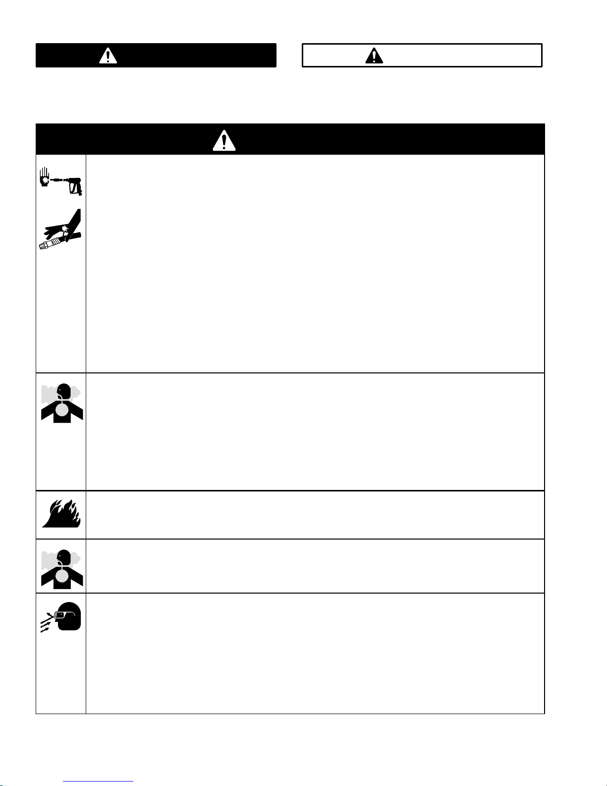
WARNING
INJECTION HAZARD
Spray from the gun, leaks, or ruptured components can inject fluid into your body and cause serious
injury. Fluid splashed in the eyes or on the skin can also cause serious injury.
DFluid injected into the skin might look like just a cut, but it is a serious injury. Get emergency
medical attention.
DDo not point gun at anyone or at any part of body, and do not stop or deflect leaks with hand, body,
glove, or rag.
DDo not put hand or fingers over spray tip.
DTighten fluid connections before you start this equipment.
DEngage the gun trigger safety latch whenever you stop spraying.
DFollow Pressure Relief Procedure on page 3 if spray tip clogs and before you clean, check, or
service this equipment.
DRepair or replace worn or damaged parts immediately.
DCheck hoses, tubes, and couplings daily. Do not repair high-pressure couplings. Replace entire
hose. Fluid hoses must have spring guards on both ends to prevent kinks and rupture.
HAZARDOUS FLUIDS
Improper handling of hazardous fluids can cause serious injury or death due to splashing in eyes,
ingestion, or bodily contamination.
DKnow specific hazards of fluid being used.
DStore hazardous fluids in approved containers. Dispose of hazardous fluids per local, state, and
national guidelines.
DWear protective eye wear, gloves, clothing, and respirator as recommended by the fluid
manufacturer.
FUEL HAZARD
The fuel used in this pressure washer is combustible and when spilled on a hot surface can ignite and
cause a fire. Do not fill the fuel tank while the engine is running or hot.
EXHAUST HAZARD
The exhaust contains poisonous carbon monoxide which is colorless and odorless.
Do not operate this equipment in a closed building.
EQUIPMENT MISUSE HAZARD
Misuse of the pressure washer or accessories could cause them to rupture and result in fluid injection,
splashing in the eyes or on the skin, or other serious injury.
DDo not alter or modify any part or factory-set adjustment of this equipment.
DDo not exceed the maximum working pressure of any component or accessory in the system.
DDo not use any chemicals that are incompatible with the wetted parts as stated in Technical Data
on page 19.
DDo not alter throttle setting.

3824111
Setup
8777B
high-pressure hose
connection
hose rack
inlet water connection:
3/4-in. garden hose
gun
high-pressure hose
wand
Check for Shipping Damage
Check the pressure washer for shipping damage.
Notify the carrier immediately if there is any
damage.
Connect High-Pressure Hose and Gun
Connect the high-pressure hose to the high-pressure
hose connection and the gun. Both of these
connections are made with quick couplers.
CAUTION
Up to 100 ft (30 m) of high-pressure hose may
be used. Longer hoses could affect sprayer
performance and chemical injector performance.
Install Spray Tip
Install the appropriate spray tip on the wand. See
Installing and Changing Spray Tips on page 5.
If you are using a Sandblaster Kit, see its separate
manual for installation instructions.
Connect to Water Supply
CAUTION
Before you connect the garden hose to the pressure
washer, check your local plumbing code regarding
cross-connection to the water supply. If required,
install a backflow preventer.
If the inlet water pressure is over 60 psi (4.1 bar), a
regulating water valve must be installed at the
garden hose connection.
Do not exceed 160_F (70_C) inlet water
temperature.
Connect a hose with at least a 3/4-in. (19 mm) ID from
the water supply to the 3/4-in. garden hose inlet. The
supply hose should not be more than 50 ft (15 m) long.
NOTE: The water supply must have a minimum flow
rate equal to that of the pressure washer. See
Technical Data on page 19.
Pressure Relief
Procedure
WARNING
INJECTION HAZARD
The system pressure must be manually
relieved to prevent the system from
starting or spraying accidentally. Fluid
under high pressure can be injected through the
skin and cause serious injury. To reduce the risk of
an injury from injection, splashing fluid, or moving
parts, follow the Pressure Relief Procedure
whenever you
DAre instructed to relieve the pressure
DStop spraying for more than 10 minutes
DCheck or service any of the system equipment
DInstall or clean the spray nozzle
1. Engage the gun trigger safety latch.
2. Turn the sprayer off, and remove the ignition cable
from the spark plug.
3. Shut off the water supply.
4. Disengage the trigger safety latch, and trigger the
gun to relieve pressure. Then engage the trigger
safety latch.
If you suspect that the spray tip or hose is clogged or
that pressure has not been fully relieved after following
the steps above: Disengage the trigger safety latch,
and trigger the gun to relieve pressure. Wrap a rag
around the hose end coupling, and VERY SLOWLY
loosen the coupling to relieve pressure gradually. Then
loosen it completely. Then clear the tip or hose.

4824111
Operation
Startup
Always use this start-up procedure to ensure that the pressure washer is started safely and properly.
DAlways engage the gun trigger safety latch when
you stop spraying even for a moment. This reduces
the risk of fluid injection or splashing in the eyes or
on the skin if the gun is bumped or triggered
accidentally.
DAlways observe the CAUTIONS in this section to
avoid costly damage to the pressure washer.
DIf you use the Sandblaster Kit, see the Sandblaster
Kit manual for detailed cleaning information.
1. Check the oil level.
NOTE: All pressure washers are equipped with a
low-oil sensor that shuts the engine off if the oil
level falls below a certain level. If the engine stops
unexpectedly, check both the oil and the fuel
levels. Check the oil level each time you refuel.
2. Check the fuel level.
WARNING
FIRE HAZARD
Do not refuel a hot engine. Refueling a
hot engine could cause a fire. Use only
fresh, clean regular or unleaded gasoline. Close
the fuel shutoff valve during refueling.
3. Turn on the water supply.
CAUTION
Never run the pressure washer without water.
Costly damage to the pump will result. Always be
sure the water supply is completely turned on
before you run the pressure washer.
4. Trigger the gun until water sprays from the tip,
indicating that the air is purged from the system.
5. Open the fuel shutoff valve. Be sure the spark plug
ignition cable is pushed firmly onto the spark plug.
Put the switch in the START position, and put the
throttle in the RUN position.
CAUTION
Do not allow the pressure washer to idle for more
than 10 minutes. Doing so could cause the
recirculating water to overheat and seriously
damage the pump. Turn off the pressure washer if
it will not be spraying at least every 10 minutes. If
heated inlet water is used, reduce this time more.
Do not operate the pressure washer with the inlet
water screen removed. The screen helps keep
abrasive sediment out of the pump, which could
clog the pump or damage the cylinders. Keep the
screen clean. Do not pump caustic materials; such
materials could corrode the pump components.
6. Pull the starter rope to start the engine. Brace one
foot on the pressure washer chassis, and pull the
starter rope out quickly. Pull and return the rope
until the engine starts.
CAUTION
Do not allow the starter rope to snap back against
the engine. Let the rope recoil gently to prevent
damage to the recoil.
NOTE: For easier starting, have one person start
the pressure washer while another person triggers
the gun.
If the engine is cold, start the engine with the
choke completely closed. In cool weather, you
might have to let the engine run with the choke
closed for the first 10 to 30 seconds. In warm
weather, open the choke completely as soon as
the engine starts.
If the engine is warm, start the engine with the
choke completely open or partially closed. When
the engine starts, open the choke completely.
5824111
Operation
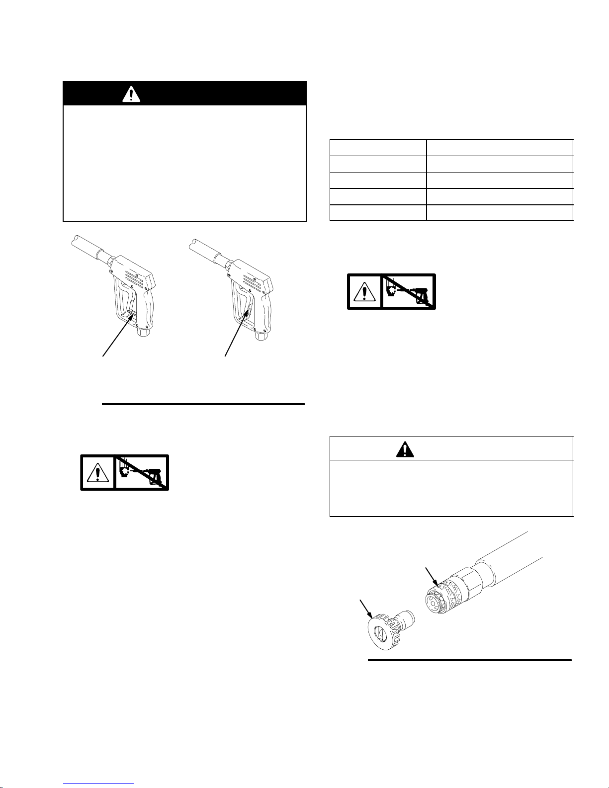
Trigger Safety Latch
WARNING
To reduce the risk of serious bodily injury, including
fluid injection and splashing in the eyes or on the
skin, always engage the trigger safety latch when
you stop spraying even for a moment. When
engaged, the trigger safety latch prevents the gun
from being triggered accidentally by hand or if it is
dropped or bumped. Be sure the latch is pushed
fully down, or it will not prevent the gun from being
triggered. See Fig. 1.
Fig. 1
engaged disengaged
04612
Trigger Safety Latch
Chemical Injector Operation
1. Relieve the pressure.
See page 3.
2. Insert the chemical filter (attached with clear tubing
to the chemical injector) into the container of
chemical.
3. Install the black large-orifice chemical tip. See
Installing and Changing Spray Tips at right.
This causes a drop in pressure that actuates the
chemical injector. Changing back to a small diameter
spray tip deactivates the chemical injector and
produces high pressure for rinsing. The chemical filter
can be left in the chemical container during high
pressure use. To regulate the flow rate of the chemical,
turn the chemical adjustment knob on the injector.
Maximum chemical flow is a full two turns
counterclockwise from the CLOSED (clockwise)
position.
Installing and Changing Spray Tips
Spray tips have 4- or 5-digit numbers on them. The
first two digits are the spray angle. Select the spray tip
appropriate for your application. Tip holding holes are
provided on the chassis.
Spray Tip Number Spray Pattern Fan Angle
00XXX 0_blaster (red)
15XXX 15_(yellow)
25XXX 25_(green)
40XXX 40_(white)
NOTE: The chemical injector tip is brass and has a
large opening and a black plastic cap.
1. Relieve the pressure.
See page 3.
2. Point the gun and wand away from yourself and
anyone else.
3. Without holding your hand over the spray tip (A),
pull back the quick coupler ring (B). Remove the
current tip and/or install a different one, and then
push back the ring. See Fig. 2.
4. Pull on the tip to be sure it is secure before you
spray again.
CAUTION
To avoid blowing the O-ring out of the quick coupler
due to the high pressure in the system, never
operate the pressure washer without a tip securely
mounted in the quick coupler.
04929
Fig. 2
A
B
This manual suits for next models
3
Table of contents
Other Sherwin-Williams Pressure Washer manuals


