Shibaura ROIbot BA-II Series User manual

Front cover
S
E
R
I
E
S
Keep this manual at hand after operators have read it thoroughly.
Operating Manual (Basic Section)
Operating Manual (Basic Section)
MODEL:CA20-M10/M40
CA20-S10/S40
CONTROLLER


I
Introduction
Thank you for selecting the ROIbot BA series.
To ensure correct usage, read this instruction manual before starting use of
the ROIbot BA series.
For information on the actuators in ROIbot BA series, refer to the Actuator
Operating Manual supplied with the actuator.
PRECAUTION
1. The contents of this manual are subject to change without prior
notice.
2. An effort has been made to ensure the contents of this manual.
If you have any questions, or find any mistakes, please contact
us.
3. Regardless of item 2 above, we will not be held responsible for
any effect caused by using this robot.

II
Contents
Chapter 1 General Safety Instruction
1.1 Important messages ···································································· 1-1
1.2 Safe Operation ············································································ 1-6
1.2.1 Auxiliary safety precautions before ROIbot installation ····················· 1-6
1.2.2 Precautions for installing the ROIbot ············································ 1-7
1.2.3 Precautions for operation of the ROIbot········································ 1-7
1.3Warranty ···················································································· 1-9
1.3.1 Warranty period ······································································ 1-9
1.3.2 Warranty details······································································ 1-9
1.3.3 Exemption of liability ································································ 1-9
1.3.4 Notes ···················································································· 1-9
Chapter 2 Devices
2.1 Features ····················································································· 2-1
2.2 System components and specifications ········································· 2-3
2.2.1 System components································································· 2-3
2.2.2 Controller specifications····························································· 2-4
(1) Master unit specifications··························································· 2-5
(2) Slave unit specifications ···························································· 2-6
(3) Various units and options··························································· 2-7
2.3 Explanation of each part······························································· 2-8
2.3.1 External dimensions and explanation of each part··························· 2-8
2.3.2 Function of each part································································ 2-9
2.3.3 Explanation of expansion input/output unit····································· 2-11
2.3.4 Explanation of Teach Pendant···················································· 2-12
2.4 Procedures from installation to operation······································· 2-15
2.4.1 Installing the controller ······························································ 2-16
2.4.2 Supply power and grounding······················································ 2-17
2.4.3 Improvement of noise resistance················································· 2-19
2.4.4 Connecting the axis and controller··············································· 2-20
2.4.5 Connecting the emergency stop circuit ········································· 2-23
2.4.6 Effect of leakage current···························································· 2-23
2.4.7 Setting the Robot Type······························································ 2-24
2.4.8 Setting the software limit and Return to Origin································ 2-26
2.4.9 Servo gain adjustment ······························································ 2-28
2.4.10 Absolute encoder backup························································· 2-29
2.5 Moving the ROIbot······································································· 2-32

III
Chapter 3 General Programming
3.1 Explanation of operation modes···················································· 3-1
3.1.1 Explanation of RUN mode·························································· 3-3
3.1.2 Explanation of PRGM mode······················································· 3-4
3.1.3 Return to Origin······································································· 3-5
3.2 General programming ·································································· 3-6
3.2.1 Basic programming ·································································· 3-10
3.2.2 Position data input···································································· 3-12
(1) Remote teaching······································································ 3-13
(2) Direct teaching ········································································ 3-15
(3) MDI (Manual Data Input)···························································· 3-17
3.2.3 Memory Clear (Initialization)······················································· 3-19
3.2.4 MOV system command words and parameters ······························ 3-22
Chapter 4 Sequential Mode
4.1 Sequential PRGM mode································································ 4-1
4.1.1 How to enter and leave PRGM (program) mode ····························· 4-1
4.1.2 Editing of steps in sequential program·········································· 4-2
4.1.3 Copy editing of sequential programs ············································ 4-4
4.1.4 Clearing of sequential programs·················································· 4-5
4.1.5 HELP function in entering a command·········································· 4-7
4.1.6 Method to restart operation of sequential mode
after turning power OFF ···························································· 4-8
4.1.7 Palletizing work with MVM commands·········································· 4-10
4.2 Sequential RUN mode ·································································· 4-16
4.2.1 AUTO mode of sequential mode ················································· 4-16
(1) Continuous operation································································ 4-16
(2) Single operation······································································· 4-17
4.2.2 STEP mode of sequential mode·················································· 4-18
4.2.3 Changing of speed during operation (override)······························· 4-29
Chapter 5 Multi-task
5.1 Multitasking················································································ 5-1
5.2 Merits of multitasking··································································· 5-1
5.3 Multitasking usage methods ························································· 5-2
5.3.1 Multitasking specifications·························································· 5-2
5.3.2 Multitasking functions and settings··············································· 5-2
5.3.3 Starting and stopping tasks························································ 5-3
5.3.4 Multitasking operation ······························································· 5-4
5.3.5 Applying timing between tasks···················································· 5-5

IV
5.4 Details on multitasking································································· 5-6
5.4.1 Task status············································································· 5-6
5.4.2 Transition of states··································································· 5-6
5.4.3 Transfer of data between tasks··················································· 5-7
5.4.4 Task priority············································································ 5-7
Chapter 6 Easy Mode
6.1 PRGM mode of easy mode···························································· 6-2
6.1.1 How to enter and leave the easy mode········································· 6-2
6.1.2 Editing easy mode program························································ 6-3
6.1.3 Copy editing of easy mode························································· 6-15
6.1.4 Clearing of easy mode programs················································· 6-16
6.2 RUN mode of easy mode ······························································ 6-17
6.2.1 AUTO mode of easy mode························································· 6-17
(1) Continuous operation································································ 6-17
(2) Single operation······································································· 6-18
6.2.2 STEP mode of easy mode························································· 6-19
6.2.3 Changing of speed during operation (override)······························· 6-20
Chapter 7 Palletizing mode
7.1 Basic flow chart of palletizing mode··············································· 7-3
7.2 PRGM mode in palletizing mode···················································· 7-4
7.2.1 How to enter and leave the PRGM mode ······································ 7-7
7.2.2 Editing palletizing mode program················································· 7-8
7.2.3 Copy editing of palletizing mode·················································· 7-11
7.2.4 Clearing of palletizing mode programs·········································· 7-12
7.2.5 How to restart operation after turning power OFF
in palletizing mode ··································································· 7-13
7.3 RUN mode of palletizing mode ······················································ 7-14
7.3.1 AUTO mode of palletizing mode·················································· 7-14
(1) Continuous operation································································ 7-14
(2) Single operation······································································· 7-17
7.3.2 STEP mode of palletizing mode ·················································· 7-17
7.3.3 Changing of speed during operation (override)······························· 7-19
Chapter 8 External Point Designation Mode
8.1 Explanation of external point designation mode······························ 8-1
8.2 Operation method of external point designation mode····················· 8-5
8.2.1 Execution with input/output························································· 8-5
8.2.2 Operation with Teach Pendant···················································· 8-6

V
8.3 Changing of speed during operation (Override)······························· 8-6
Chapter 9 Pulse train input mode
9.1 System······················································································· 9-1
9.1.1 System configuration method ····················································· 9-1
9.1.2 Specifications of pulse train input mode········································ 9-2
9.2 Input/output signals····································································· 9-3
9.2.1 Input/output connector signal names and pin numbers····················· 9-3
9.2.2 Functions of each input/output signal ··········································· 9-4
9.2.3 Example of input/output signal connection····································· 9-8
9.3 Operation methods······································································ 9-10
9.3.1 Designation of pulse train input mode··········································· 9-10
9.3.2 Matters to be set for pulse train input mode ··································· 9-10
9.3.3 Protective functions·································································· 9-11
9.4 Precautions for operation ····························································· 9-12
9.5 Operation procedures ·································································· 9-12
Chapter 10 Connection with External Devices
10.1 Input/output signal····································································· 10-1
10.1.1 Master unit input/output connector signal names
and pin numbers ···································································· 10-1
10.1.2 Slave unit input/output connector signal names
and pin numbers ···································································· 10-2
10.1.3 Expansion input/output signal names and pin Nos.························ 10-8
10.1.4 Names of general-purpose input/output ports
and Teach Pendant displays····················································· 10-9
10.1.5 Example of input/output signal connection··································· 10-10
10.2 Details of system input/output function ········································ 10-13
10.2.1 Return to origin input······························································· 10-13
10.2.2 Start input············································································· 10-13
10.2.3 Stop input············································································· 10-14
10.2.4 Reset input ··········································································· 10-14
10.2.5 Robot single operation input ····················································· 10-14
10.2.6 Continuous start input ····························································· 10-15
10.2.7 Escape input········································································ 10-15
10.2.8 Pause (temporary stop) input ·················································· 10-15
10.2.9 Program No. selection input······················································ 10-16
10.2.10 Palletizing input···································································· 10-17
10.2.11 Running output····································································· 10-17
10.2.12 Error output········································································· 10-17
10.2.13 Positioning complete output···················································· 10-17

VI
10.2.14 Return to origin complete output ·············································· 10-17
10.2.15 Input wait output··································································· 10-18
10.2.16 Pausing (temporarily stopped) output········································ 10-18
10.2.17 READY output ····································································· 10-18
10.2.18 Individual task positioning complete output································· 10-18
10.2.19 Individual task return to origin complete output···························· 10-18
10.2.20 Battery alarm output······························································ 10-18
10.3 RS-232C communication specifications········································ 10-18
Chapter 11 CC-Link
11.1 CC-Link Function ······································································ 11-1
11.1.1 Overview·············································································· 11-1
11.1.2 CC-Link specifications····························································· 11-2
11.1.3 How to attach the CC-Link module············································ 11-2
11.1.4 Explanation of CC-Link component and external dimensions········· 11-3
11.1.5 Connection of exclusive CC-Link cable······································ 11-4
11.1.6 CC-Link settings···································································· 11-4
11.2 Connection with External Devices··············································· 11-5
11.2.1 List of master unit I/O signals··················································· 11-5
11.2.2 System I/O ··········································································· 11-6
11.2.3 Name of general-purpose I/O port and teach pendant display········ 11-7
11.2.4 Jog input/output····································································· 11-8
11.3Data Communication ································································· 11-10
11.3.1 Overview of data communication ·············································· 11-10
11.3.2 Command mode···································································· 11-11
11.3.2.1 Transmitting and receiving data ·········································· 11-11
11.3.2.2 Command table ······························································· 11-13
11.3.2.3 Descriptions on each command ·········································· 11-14
11.3.3 Monitor mode········································································ 11-21
11.3.3.1 Data receiving method ······················································ 11-21
11.3.3.2 List of monitor types·························································· 11-22
11.3.3.3 Explanation of monitors····················································· 11-22
11.4Speed control mode through CC-Link ········································· 11-27
11.4.1 Overview·············································································· 11-27
11.4.2 Speed control specifications ···················································· 11-27
11.4.3 Items prohibited····································································· 11-27
11.4.4 Settings of speed control mode ················································ 11-28
11.4.5 List of I/O signals··································································· 11-28
11.4.6 List of I/O data ······································································ 11-29
11.4.7 Details of I/O signals ······························································ 11-30
11.5Selection table extension in external point designation mode ······· 11-34
11.5.1 Overview·············································································· 11-34

VII
11.5.2 How to set selection table extension·········································· 11-34
11.5.3 Assignment of input signals and tables······································ 11-35
11.6Maximum torque limit function ··················································· 11-38
11.6.1 Overview·············································································· 11-38
11.6.2 Specifications for the maximum torque limit function ···················· 11-38
11.6.3 Setting of the maximum torque limit function······························· 11-38
11.6.4 Setting of a maximum torque limit value····································· 11-39
11.6.5 Special I/O signals ································································· 11-39
11.7 CC-Link status ·········································································· 10-41
Chapter 12 DeviceNet
12.1 DeviceNet Function ··································································· 12-1
12.1.1 Overview·············································································· 12-1
12.1.2 DeviceNet specifications ························································· 12-1
12.1.3 How to attach the DeviceNet module········································· 12-2
12.1.4 Explanation of DeviceNet component and external dimensions ······ 12-2
12.1.5 Connection of exclusive DeviceNet cable ··································· 12-4
12.1.6 DeviceNet settings································································· 12-4
12.2 Connection with External Devices··············································· 12-5
12.2.1 List of master unit I/O signals··················································· 12-5
12.2.2 System I/O ··········································································· 12-6
12.2.3 Name of general-purpose I/O port and teach pendant display········ 12-7
12.2.4 Jog input/output····································································· 12-8
Chapter 13 Parameter Setting
13.1 How to enter and leave the PARA mode········································ 13-1
13.2 Method of mode setting······························································ 13-2
13.2.1 Designation of single operation mode input bit······························ 13-3
13.2.2 Designation of continuous start input bit······································ 13-3
13.2.3 Designation of escape input bit·················································· 13-3
13.2.4 Designation of pause input bit··················································· 13-4
13.2.5 Designation of program selection input bit ··································· 13-4
13.2.6 Designation of return to origin input bit········································ 13-5
13.2.7 Designation of pausing output bit··············································· 13-5
13.2.8 Designation of input wait output bit············································· 13-5
13.2.9 Setting of Teach Pendant display (Japanese/English) mode············ 13-5
13.2.10 OFF (Invalid), easy, point, pulse 1, pulse 2································· 13-6
13.2.11 Setting of general-purpose output clear mode
during emergency stop and reset ············································· 13-6
13.2.12 Setting of state when continuous start is valid (Input ON)··············· 13-7
13.2.13 Setting of state when continuous start is valid (Input OFF)·············· 13-7
13.2.14 Setting of direct output bit······················································· 13-7

VIII
13.2.15 Designation of READY output bit ············································· 13-8
13.2.16 Designation of palletizing input bit ············································ 13-8
13.2.17 Expansion input/output during external point designation mode
Valid/Invalid ········································································· 13-8
13.2.18 Setting of task positioning output·············································· 13-8
13.2.19 Setting of task return to origin output········································· 13-9
13.2.20 Setting of CC-Link································································ 13-9
13.2.21 Setting of DeviceNet····························································· 13-10
13.2.22 Designation of battery alarm output bit····································· 13-10
13.2.23 Moving coordinate table number output
in external point designation mode ············· 13-10
13.3 Parameter 1 setting···································································· 13-11
13.3.1 Setting of software limit value (upper limit)··································· 13-12
13.3.2 Setting of software limit value (lower limit)···································· 13-12
13.3.3 Setting of servo gain (position/speed)········································· 13-12
13.3.4 Setting of pass area································································ 13-13
13.3.5 Setting of origin offset value······················································ 13-13
13.3.6 Setting of sequence of return to origin ········································ 13-14
13.3.7 Setting of JOG speed······························································ 13-15
13.3.8 Setting of JOG inching movement·············································· 13-15
13.4 Parameter 2 setting··································································· 13-16
13.4.1 Setting of axis display······························································ 13-18
13.4.2 Setting of in-position data value················································· 13-18
13.4.3 Setting of overflow data value ··················································· 13-18
13.4.4 Setting of feed forward data value·············································· 13-19
13.4.5 Setting of direction of motor revolution········································ 13-19
13.4.6 Setting of maximum speed······················································· 13-19
13.4.7 Setting of return to origin speed················································· 13-20
13.4.8 Setting of return to origin method··············································· 13-22
13.4.9 Setting of origin sensor logic····················································· 13-23
13.4.10 Setting of high speed return to origin position ····························· 13-23
13.4.11 Setting of lead······································································ 13-23
13.4.12 Setting of encoder No. of divisions ··········································· 13-24
13.4.13 Setting of encoder pulse multiplier············································ 13-24
13.4.14 Setting of encoder type·························································· 13-24
13.4.15 Setting of task and axis combination········································· 13-25
13.4.16 Setting of task order of priority················································· 13-25
13.4.17 Setting of task point table ······················································· 13-26
13.4.18 Setting of No. of task steps····················································· 13-26
13.4.19 BA I/O compatibility mode ······················································ 13-26
13.5 How to set the tables·································································· 13-27
13.5.1 Setting of coordinate (point) table ·············································· 13-28
13.5.2 Setting of speed table······························································ 13-28
13.5.3 Setting of acceleration/deceleration table····································· 13-29
13.5.4 Setting of MVM table······························································· 13-30

IX
Chapter 14 Monitoring
14.1 Program step No. monitoring ······················································ 14-2
14.2 Input/output monitoring······························································ 14-3
14.3 Counter and timer monitoring······················································ 14-5
14.4 Coordinate monitoring································································ 14-6
14.5 Origin sensor/encoder Z-phase pulse monitoring ·························· 14-8
Chapter 15 Search Function
15.1 Search of sequential step No.······················································ 15-1
15.2 Search of tag No. ······································································· 15-1
15.3 Search of easy step No. ······························································ 15-2
15.4Search of easy program No. ························································ 15-2
15.5Search of palletizing program No. ················································ 15-3
15.6Search of palletizing program screen No.······································ 15-3
Chapter 16 Manual Operation of General-purpose Outputs
16.1 Manual output using function keys··············································· 16-1
16.2 Manual output of random bit designation from PRGM mode ··········· 16-2
Chapter 17 Other Handy Operations
17.1 Teach Pendant ON/OFF ······························································ 17-1
17.2 Reset operation ········································································· 17-2
17.3 Counter direct set ······································································ 17-3
17.4 Version display·········································································· 17-4
17.5 JOG operation (Manual operation of axis)····································· 17-5
17.6 Clearing (initializing) coordinate table ·········································· 17-7

X
17.7 BA I/O Compatibility Mode·························································· 17-8
17.7.1 Selection method of BA I/O compatibility mode ··························· 17-8
17.7.2 Operation specifications for return to origin complete output
and positioning complete output·············································· 17-9
17.8 Movement operation on coordinate table setting screen ··············· 17-11
Chapter 18 Commands
ACC (Setting acceleration/deceleration)················································ 18-4
BRAC (Counter jump)········································································· 18-5
CAL (Unconditional call)···································································· 18-6
CALC (Counter conditional call)···························································· 18-7
CALI (Input conditional call)································································ 18-8
CALT (Timer conditional call)······························································· 18-10
CNT (Preset counter value) ······························································· 18-11
CNT+ (Count up)··············································································· 18-12
CNT(Count down)··········································································· 18-13
CNTC (Clear all counters)···································································· 18-14
END (End)······················································································ 18-15
HOME (Return to origin) ······································································ 18-16
IN (Waiting for input)····································································· 18-17
INPC (Setting general-purpose port input to counter) ······························· 18-18
JMP (Unconditional jump) ································································· 18-19
JMPC (Counter conditional jump)·························································· 18-20
JMPI (Input conditional jump)······························································ 18-21
JMPT (Timer conditional jump)····························································· 18-23
LOOP (Loop for MVM)········································································ 18-24
MINI (Initial counter value for MVM)····················································· 18-25
MOVP (Axis Movement to the Indirectly Designated Point
by Coordinate Table) ································································ 18-26
MVB (Move (return) to point immediately before the current position)·········· 18-28
MVE (Escape move)········································································· 18-29
MVM (Palletizing movement)······························································· 18-31
NOP (No function)············································································ 18-33
OFS (Offset)··················································································· 18-34
OUT (General-purpose port output) ····················································· 18-35
OUTC (General-purpose port output of counter value)······························· 18-37
OUTP (General-purpose port pulse output) ············································· 18-38
PSEL (Program selection)··································································· 18-39
RET (Return)·················································································· 18-40
SPD (Setting speed)········································································· 18-41
STOP (Stop)····················································································· 18-42
SVOF (Servo-off)··············································································· 18-43
SVON (Servo-on)··············································································· 18-44
TAG (Tag)······················································································ 18-45
TCAN (Task forced end) ····································································· 18-46
TIM (Waiting)················································································· 18-47
TIMP (Timer preset)·········································································· 18-48
TRSA (Task restart)··········································································· 18-49
TSTO (Task temporary stop)································································ 18-50
TSTR (Task start)·············································································· 18-51

XI
Chapter 19 Error messages
19.1 Error Display······················································································· 19-1
19.2 Error Table ························································································· 19-2
19.3 Flashing of status display LED····························································· 19-8
Chapter 20 BA-C series
20.1Specification ··········································································· 20-1
20.2Explanation of each part··························································· 20-2
20.3Connections············································································ 20-6
20.4Selecting the power supply······················································· 20-7
20.5Installing················································································· 20-8
20.6Supply power and grounding ···················································· 20-9
20.7Improvement of noise resistance··············································· 20-10
20.8Connecting controllers····························································· 20-10
20.9Resolver ABS backup······························································· 20-11
20.10 Regenerative Resistors ···························································· 20-13
20.10.1 Specifications······································································ 20-13
20.10.2 External dimensions ····························································· 20-14
20.10.3 Installation ·········································································· 20-14
20.10.4 Connection example····························································· 20-15
Chapter 21 Maintenance and Inspection
21.1 Procedures before and after inspection and maintenance··············· 21-1
21.2 Inspection before operation ························································ 21-2
21.3 Periodic inspection ···································································· 21-2
21.3.1 Inspection of timing belt··························································· 21-3
21.4 Lubrication················································································ 21-4
21.5 Cleaning ··················································································· 21-5

XII
21.6 Spare parts ··············································································· 21-5
21.6.1 Controller spare parts······························································ 21-5
21.6.2 Axis spare parts····································································· 21-5

1 –1
Chapter 1 General Safety Instruction
1.1 Important messages
READ THIS MANUAL carefully for important information about safety, handling, installation,
operation, maintenance, and parts replacements.
This manual and all accompanying drawings should be considered a permanent part of the
equipment.
They should be readily available for review and reference at all times.
IMPORTANT MESSAGES
Read this manual and follow its instructions. Signal words such as
DANGER, WARNING and CAUTION will be followed by important
safety information that must be carefully reviewed.
D
A
N
G
E
R
WARNING
C
A
U
T
I
O
N
NOTE
WARNING
Use only SHIBAURA-MACHINE-authorized replacement parts.
WARNING
This equipment is designed and built in accordance with applicable
safety standards in effect on the date of manufacture.
Unauthorized modifications will void the warranty and can result in severe
injury, death and property damage.
Do not make any electrical or mechanical modifications to this equipment
without the written approval of the manufacturer.
: Indicates a situation which will result in death, serious injury, or severe
property damage if you do not follow instructions.
: Means that you might be seriously injured or killed if you do not follow
instructions. Severe property damage might also occur.
: Means that you might be injured if you do not follow instructions.
Equipment damage might also occur.
: Gives you helpful information.
: Means that the description of glossaries is written and the corresponding
page is indicated.

1 –2
QUALIFIED PERSONS ONLY
Only qualified persons are to install, operate or service this equipment according to all
applicable codes and established safety practices.
A qualified person must:
1) Carefully read the entire instruction manual.
2) Be skilled in the installation, construction or operation of the equipment and aware of
the hazards involved.
3) Be trained and authorized to safely energize, de-energize, clear, ground, lockout and
tag circuits in accordance with established safety practice.
4) Be trained and authorized to perform the service, maintenance or repair of this
equipment.
5) Be trained in the proper care and use of protective equipment such as rubber gloves,
hard hat, safety glasses, face shield, flash clothing, etc. in accordance with established
practices.
6) Be trained in rendering first aid.

1 –3
D
A
N
G
E
R
HAZARDOUS VOLTAGE will cause severe injury, death, fire, explosion
and property damage.
Disconnect and lock out primary and control circuit power before servicing.
This equipment contains capacitors which stay charged after power has been shut off.
Wait for a minimum of 3 minutes before servicing.
D
A
N
G
E
R
MOVING PARTS will cause severe injury, death or property damage.
An effective safety barrier with appropriate interlocks and emergency stop provisions must be
placed around the robot to protect all personnel from the intended and unintended movement
of the robot and the potential of throwing of work pieces and materials by the robot.
No personnel should be allowed within this area during operation of the robot.
Never defeat, modify or bypass any of the safety interlocks.
Never modify the robot arm or controller without written permission of the manufactures.
Only properly trained and qualified persons are to install, program, operate or service this
equipment according to all applicable codes and established safety practices.
D
A
N
G
E
R
Do not get water on the inside or outside or the robot and do not wipe it off with water.
Doing so could lead to electric shocks or faults.
(If the robot is dirty, wipe it off with a strongly wrung out cloth.)
(Do not use organic solvents such as paint thinner or benzene.)
Do not insert or drop in foreign matter such as metals into the robot from the ventilation holes.
Doing so could lead to fires or electric shocks.
MOVING PARTS OR POTENTIAL MOVING PARTS can cause severe
injury, death or property damage.
Do not insert your fingers or any objects into the openings on this robot.
Horizontal mounting only. The "X and "Y" axes do not have a brake.
When using the side mounted motor axis vertically, periodically inspect the belt, and replace it
after every 3,000 hours of operation.
If use is continued after the belt's life, the belt could break. This could cause the slider to drop
unexpectedly and lead to injuries.
EMERGENCY STOP
Emergency stop connect the emergency stop switch to the terminal of emergency stop input
so that you can operate it from outside the safety barrier in an emergency.
WARNING
WARNING

1 –4
ELECTRICAL SHOCK
This equipment must be properly grounded as per the national electrical code to prevent
potential of electric shock and to reduce to possibility of electrical noise causing an
operational error.
HOT SURFACE CONTACT may result in burn injury.
The motor is hot during operation.
Allow sufficient time for cooling before servicing.
The internal heat sink and cement resistor are hot while operating.
Allow sufficient time for cooling before servicing.
Replace the fuse and the battery with specified them only.
Do not place the battery or electrolytic capacitor in fire.
Doing so could lead to explosions.
Always install the enclosed terminal block cover on the power supply terminal block.
Failure to cover the terminal block could lead to electric shocks when the terminal block is
contacted.
Do not use this robot on body parts, for example as a massage machine.
Personal injury could result from incorrect teaching or operation.
This robot does not have a sealed structure.
The ball screw grease or belt wear chips could scatter out of the openings during use.
Take measures to prevent entry of this matter when using this robot for applications related to
foodstuffs or chemicals, etc.
Use a rigid installation frame for the robot unit.
If the frame rigidity is insufficient, vibration (resonance) could occur during robot operation
and could adversely effect the work.
Note that the brake at servo motor on the actuator may be released due to either
programming the wrong Robot-Type or Memory lnitializing.
lnput Robot -Type and execute Memory -Initializing correctly.
WARNING
WARNING
WARNING
WARNING

1 –5
C
A
U
T
I
O
N
AMBIENT POTENTIAL OR EQUIPMENT DAMAGE
Do not install in area where the ambient temperature exceeds 40°C or where equipment is
subjected to extreme temperature changes that could condensation or where the equipment
is subjected to direct sunlight.
Keep the ambient temperature of controller at 0 to 40°C.
Do not use in the place exposed heavy shock and vibrations.
Do not install in environments where conductive dust, corrosive gases, or oil mist are present.
Equipment damage will occur.
Install in a place where are the air convection or provide cooling device.
High temperature may cause failure or deterioration.
An ambient temperature increase when it is installed a narrow space since controller itself
generates a heat or receive from other devices.
C
A
U
T
I
O
N
HEAVY
Attempting to manually lift the robot can cause serious injury or equipment damage.
Always use suitable lifting equipment.
C
A
U
T
I
O
N
DISPOSAL
Contact your state environmental agency for details on disposal of electrical components and
packaging in your particular area.
1 –6
1.2 Safe Operation
Take measures to satisfy the following items when using the ROIbot BA series.
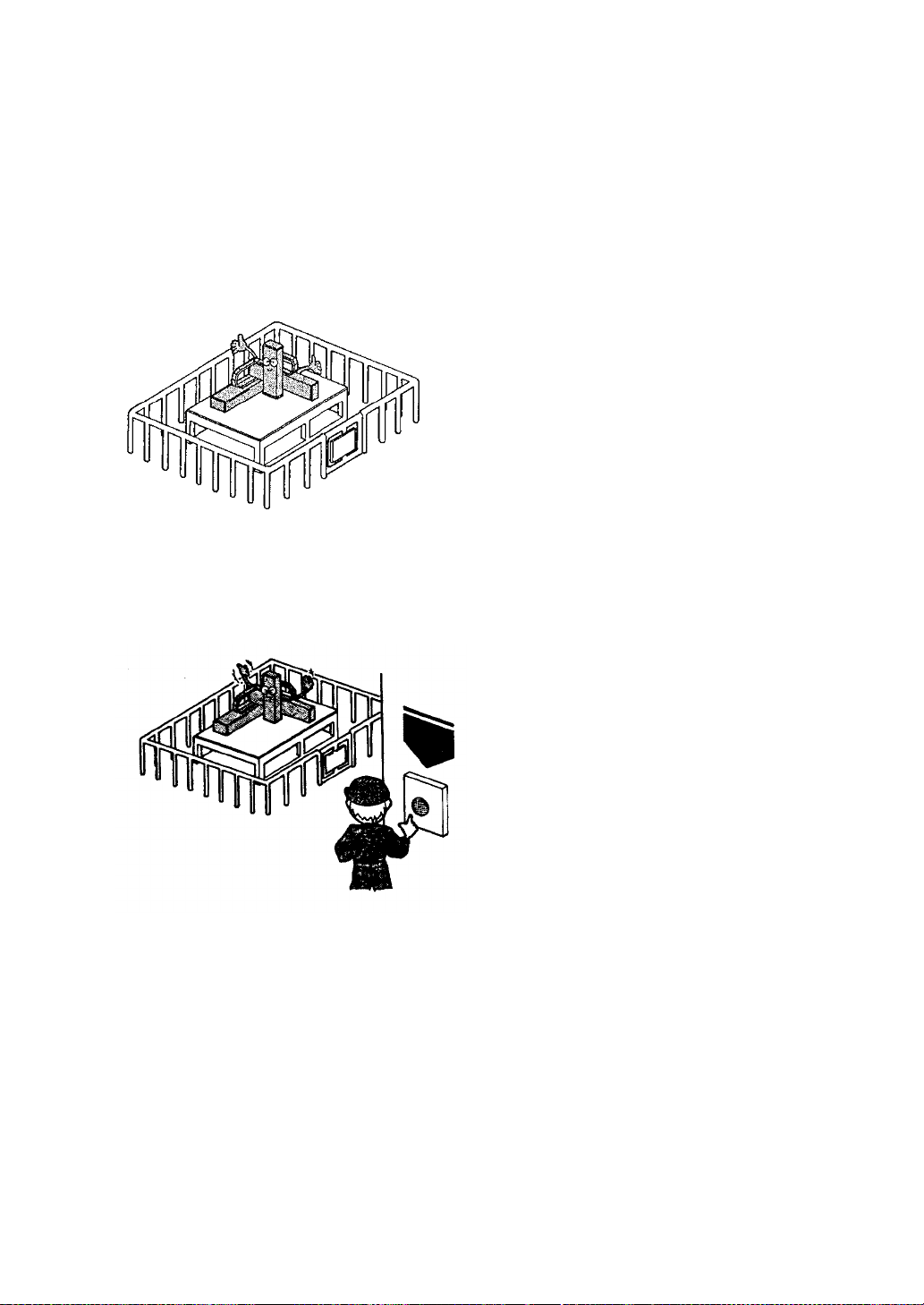
1.2.1 Auxiliary safety precautions before ROIbot installation
(1) Install a safety fence to prevent people from entering the area of ROIbot operation.
1. The fence should be strong enough to
withstand any force it might be expected
to encounter during normal ROIbot or
other operations. It should not be easy to
breach, climb over or move.
2. It should be constructed of safe material
with no sharp edges.
3. The foundation should be rigid and
immobile.
4. Any door on the fence must be interlocked
with the ROIbot so that ROIbot operations
stop automatically when the door is
opened.
(2) Install an emergency stop device in an easily accessible place to enable an operator to
quickly stop the ROIbot in case of an emergency.
1. When an emergency stop switch is
operated the braking device must stop the
ROIbot quickly without fail.
2. The emergency stop button or other
activating device should be red.
3. The activating device must be readily
accessible so the operator can easily
trigger it by, for example, pressing, pulling,
or touching a switch or by blocking a light
beam.
4. Once triggered, the emergency stop
device must be restorable only through
deliberate action of an operator. It must
not allow operations to be resumed
automatically or through inattention on the
part of an operator.
(3) No alteration or modification of the products is allowed.
Emergency
STOP
button
This manual suits for next models
3
Table of contents
Other Shibaura Controllers manuals


Popular Controllers manuals by other brands

Milnor
Milnor Milnor Phase 7.2.2 user manual

Dresser
Dresser MAR Series installation manual

ComAp
ComAp IGS-NT Series installation guide

Dwyer Instruments
Dwyer Instruments DCT1000DC Series Specifications-installation and operating instructions

Zikodrive
Zikodrive ZDSMUL2-24 quick start guide

ICP DAS USA
ICP DAS USA WP-5231PM-3GWA-CE7 quick start


Prozeda
Prozeda primos 200 SR Installation and operating instructions

Gavita
Gavita Master EL2 user manual

Hitachi
Hitachi H Series instruction manual

IXYS
IXYS Zilog ZAURA quick start guide

Omron
Omron E5CK-AA1-500 AC/DC24 user manual

Tekram Technology
Tekram Technology HOYA IrWave 520UK USB-IrDA installation guide