Shibaura ST318 User manual

ST318/ST321/ST324
MODEL

Electro-magnetic Interference (EMC)
This tractor complies strictly with the European Regulations on electro-magnetic emissions. However,
interference may arise as a result of add-on equipment which may not necessarily meet the required
standards. As such interference can result in serious malfunction of the unit and/or create unsafe situations,
you must o serve the following:
Ensure that eac h piece of non-SHIBAURA equipment fitted to the tractor ears the
CE mark.
The m ax im um power of em ission equipment(r adio,tele phones,etc.) must not exceed
the limits imposed y the national authorities of the countr y wher e you use the
tractor.
The electro-magnetic field genera ted y the add-on system should no t exceed
24V/m at any tim e and at a ny location in the prox imity of electronic com ponents.
Failur e to com ply with these rules will render the SH IBAURA warranty null and void.
Printed in Japan
S318,321,324 300812560 050002-003F

1
GENERAL INFORMATION
PLEA SE R EAD CAR EF ULLY :
For a complete lis t of the pre-deliver y service ch ecks performed b y your dealer, r efer to
the PR E-DELIVER SERVICE check list fo und at th e back of this m anual. Keep one c opy
as your rec ord of the s ervic e perform ed. The other should be r emoved from the m anual
and kept by your dealer. MAKE SU RE THAT BOTH COPIES ARE CO MPLETED AND THAT
OU AND THE DEALER SIGN BOTH COPIES .
After you have operated your t ractor for fifty hours, tak e this manual and your tracto r to
your d ealer. He will then perf orm the factor y rec ommended 50-HOUR SERVICE as li sted
on the lo wer portio ns at t he back of this manual - without char ge - exc ept for
lubricant, oil, or f ilters replaced as part of norm al m aintenance. MAKE SURE THAT OU
AND THE DEALER SIGN BOTH COPIES .
A PRODUCT IDENTI FICATION PLATE is locate d on the right-hand side of the front fram e.
The numbers on the plate are important should your tractor re quire future service. For
your convenience, have your dealer recor d the num bers in t he appropri ate spaces bel ow.
SHIBAUR A po licy is one of continuo us i mprovement, an d the right to c hange prices,
specification or equipment at any time without notice is reser ved.
All data given in th is manua l is subjec t to produc tion variations . Dim ensions an d weights
are approx im ate o nly and the illus trations do not n ecessaril y s how tractors in s tandard
condition. For exact information about an y particular tractor please consult your
SHIBAUR A Tractor Dealer.

2
CONTENTS
GENERAL INFORMATION····················································································································1
INTERNATIONAL S MBOLS················································································································3
SAFET PRECAUTIONS ···············································································································4 - 7
CONTROLS, INSTRUMENTS AND OPERATION ···································································· 8 - 29
SEAT, SEAT BELT AND ROPS ·································································································· 8 - 9
LIGHTING··········································································································································10
INSTRUMENT PANEL, KE SWITCH ··················································································· 11 - 12
STARTING THE ENGINE ················································································································12
STOPPING THE ENGINE················································································································13
BREAK-IN PROCEDURES ··············································································································13
THROTTLE CONTROLS ·················································································································14
BRAKE CONTROLS·························································································································15
TRANSMISSION, FOUR-WHEEL DRIVE AND PTO ···························································· 16 - 20
FOUR-WHEEL DRIVE ··················································································································16
MECHANICAL TRANSMISSION··························································································16 - 17
H DROSTATIC TRANSMISSION ······················································································ 17 - 18
CLUTCH PEDAL····························································································································18
DIFFERENTIAL CONTROL·································································································· 18 - 19
PTO CONTROLS AND OPERATION··················································································19 - 20
TOWING THE TRACTOR················································································································20
HOOD LUTCH···································································································································21
THREE POINT LINKAGE·················································································································21
H DRAULIC LIFT S STEM ···································································································· 22 - 25
DRIVING THE TRACTOR················································································································26
WHEEL TREAD SETTINGS ············································································································27
TRACTOR WEIGHTING ·········································································································· 28 - 29
TIRE PRESSURES ··························································································································29
LUBRICATION AND MAINTENANCE ························································································30 - 52
LUBRICATION AND MAINTENANCE CHART ··············································································30
FUEL AND LUBRICANTS········································································································ 31 - 33
FUEL AND LUBRICANT SERVICE PROCEDURES·····························································33 - 38
GENERAL MAINTENANCE ·····································································································38 - 50
TRACTOR STORAGE·············································································································· 51 - 52
GENERAL TORQUE SPECIFICATION TABLE·············································································53
SPECIFICATIONS························································································································ 54 - 56
SAFET AND INSTRUCTION DECALS ····················································································57 - 59
PREDELIVER AND 50-HOUR SERVICE ················································································ 61 - 63

SAFETY PRECAUTIONS
The following precautions are suggested to help pre ent accident
4
PERSONAL SAFETY
Throughout this manual and on machine decals,
you will find precautionary statements
( “CAUTION , WARNNG , and “DANGER ) fol-
lowed by specific instructions. These specifica-
tions are intended for the personal safety of you
and those working with you. Please take the time
to read them.
The word “CAUTION is used where a
safe behavioral practice according to
operating and maintenance instruc-
tions and common safety practices will
protect the operator and others from
accident involvement.
The word “WARNING denotes a po-
tential or hidden hazard, which has a
potential for serious injury. It is used
to warn operators and others to exer-
cise every appropriate means to avoid
a surprise involvement with machinery.
The word “DANGER denotes a for-
bidden practice in connection with a
serious hazard.
Failure to follow the “CAUTION , “W ARNING ,
and “DANGER instructions may result in bodily
injury or death.
MACHINE SAFETY
Additional precautionary statements
(“ATTENTION , and “IMPORTANT ) are followed
by specific instructions. These statements are
intended for machine safety.
ATTENTION
: The word “ATTENTION is use to
warn the operator of potential machine damage if
a certain procedure is not follows.
IMPORTANT
: The word “IMPORTANT is used
to inform the reader of something he needs to
know to prevent minor machine damage if a cer-
tain procedure is not follows.
A careful operator is the best operator. Most ac-
cidents can be avoided by observing certain pre-
cautions. Read and take the following precau-
tions before operating this tractor to help prevent
accidents. Equipment should be operated only by
those who are responsible and instructed to do
so.
SAFETY AND THE TRACTOR
1. Read the Operator’s Manual carefully be-
fore using the tractor. Lack of operating
knowledge can lead to accidents.
2. Use an approved Roll bar and Seat Belt for
safe operation. Overturning a tractor with-
out a roll bar can result in death or injury. If
your tractor is not equipped with a rollbar
and seat belt, see your SHIBAURA Tractor
Dealer.
3. Use the handholds and step plates when
getting on and off the tractor to prevent
falls. Keep steps and platform cleared of
mud and debris.
4. Do not permit anyone but the operator to
ride on the tractor. There is no safe place
for extra riders.
5. Keep all safety decals clean of dirt and
grime, and replace all missing, illegible, or
damaged safety decals. See the list of de-
cals in the Decal section of this manual.
SERVICING THE TRACTOR
1. The cooling system operates under pres-
sure, which is controlled by the radiator cap.
It is dangerous to remove the cap while
system is hot. Always turn cap slowly to the
first stop and allow the pressure to escape
before removing the cap entirely.
2. Do not smoke while refueling the tractor.
Keep any type of open flame away. Wait for
engine to cool before refueling.

SAFETY PRECAUTIONS
The following precautions are suggested to help pre ent accident
5
3. Keep the tractor and equipment, particularly
brakes and the steering, maintained in a re-
liable and satisfactory condition to ensure
your safety and comply with legal require-
ments.
4. Keep open flame away from battery or cold
weather starting aids to prevent fires or ex-
plosions. Use jumper cables according to
instructions to prevent sparks, which could
cause explosion.
5. Stop the engine before performing any ser-
vice on the tractor.
6. Escaping hydraulic/diesel fluid under pres-
sure can penetrate the skin causing serious
injury. If fluid is injected into the skin, ob-
tain medical attention immediately or gan-
grene may result.
* DO NOT use your hand to check for leaks.
Use a piece of cardboard or paper to search
for leaks.
* Stop engine and relieve pressure before
connecting or disconnecting lines.
* Tighten all connections before starting en-
gine or pressurizing lines.
7. Do not modify or alter or permit anyone
else to modify or alter this tractor or any of
its components or any tractor function
without first consulting SHIBAURA Tractor
Dealer.
8. The fuel oil in the injection system is under
high pressure and can penetrate the skin.
Unqualified persons should not remove or
attempt to adjust a pump, injector, nozzle
or any other part of the fuel injection sys-
tem. Failure to follow these instructions can
result in serious injury.
9. Continuous long term contact with used en-
gine oil may cause skin cancer. Avoid pro-
longed contact with used engine oil. Wash
skin promptly with soap and water.
10. Some components on your tractor, such as
gaskets and friction surfaces (brake linings,
clutch linings etc.), may contain asbestos.
Breathing asbestos dust is dangerous to
your health. You are therefore advised to
have any maintenance of repair operations
on such components carried out by an au-
thorized SHIBAURA Tractor Dealer. If
however, service operations are to be un-
dertaken on parts that contain asbestos,
the essential precautions listed below must
be observed:
* Work out of doors or in a well-ventilated
area.
* Dust found on the tractor or produced during
work on the tractor should be removed by
extraction not by blowing.
* Dust waste should be dampened, placed in a
sealed container and marked to ensure safe
disposal.
* If any cutting, drilling, etc., is attempted on
materials containing asbestos, the item
should be dampened and only hand tools or
low speed power tools used.
OPERATING THE TRACTOR
1. Apply the parking brake, place the PTO
lever in the “OFF position, the lift control
lever in the down position, the remote con-
trol valve levers in the neutral position, and
the transmission in neutral before starting
the tractor.
2. Do not start the engine or operate controls
while standing beside the tractor. Always sit
in the tractor seat when starting the engine
or operating controls.
3. Do not bypass the neutral start switches.
Consult your SHIBAURA Tractor Dealer if
your neutral start controls malfunction. Use
jumper cables only in the recommended
manner. Improper use can result in tractor
runaway.
4. Avoid accidental contact with the gear shift
levers while the engine is running. Unex-

SAFETY PRECAUTIONS
The following precautions are suggested to help pre ent accident
6
pected tractor movement can result from
such contact.
5. Disengage PTO, shut off the engine and
apply the parking brake before getting off
the tractor.
6. Do not park the tractor on a steep incline.
7. Do not operate the tractor engine in an en-
closed building without adequate ventilation.
Exhaust fumes can cause death.
8. If power steering or engine ceases operat-
ing, stop the tractor immediately.
9. Pull only from the drawbar or the lower link
drawbar in the down position. Use only a
drawbar pin that locks in place. Pulling from
the tractor rear axle or any point above the
axle may cause the tractor to upset.
10. If the front end of the tractor tends to rise
when heavy implements are attached to the
three-point hitch, install front end or front
wheel weights. Do not operate the tractor
with a light front end.
11. Always set the hydraulic selector lever in
position control when attaching equipment
and when transporting equipment. Be sure
hydraulic couplers are properly mounted
and will disconnect safety in case of acci-
dental detachment of implement.
12. Do not leave equipment in the raised posi-
tion.
13. Use the Flasher/Turn Signal Lights and
SMV signs when traveling on public roads
both day and night unless prohibited by
law.
14. Be sure tractor lights are adjusted to pre-
vent blinding an oncoming vehicle operator.
DRIVING THE TRACTOR
1. Watch where you are going especially at
row ends, on roads, around trees and low
hanging obstacles.
2. To avoid upsets drive the tractor with care
and at speeds compatible with safety, es-
pecially when operating over rough ground,
when crossing ditches or slopes, and when
turning corners.
3. Lock tractor brake pedals together when
transporting on roads to provide two wheel
braking.
4. Keep the tractor in the same gear when
going downhill as used when going uphill.
Do not coast or free wheel down hills.
5. Any towed vehicle whose total weight ex-
ceeds that of the towing tractor must be
equipped with brakes for safe opera ion.
6. When the tractor is stuck or tires are frozen
to the ground, back up the tractor to pre-
vent upset.
7. Always check overhead clearance, espe-
cially when transporting the tractor.
8. When operating at night, adjust lights to
prevent blinding an oncoming driver.
OPERATING THE PTO
9. When operating PTO driven equipment,
shut off the engine and wait until the PTO
stops before getting off the tractor and dis-
connecting the equipment.
10. Do not wear loose clothing when operating
the power take off, or when near rotating
equipment.
11. When operating stationary PTO driven
equipment, always place both gear shift
levers in neutral, apply the tractor parking
brake and block the rear wheels front and
back.
12. To avoid injury, do not clean, adjust, unclog
or service PTO driven equipment when the
tractor engine is running.

SAFETY PRECAUTIONS
The following precautions are suggested to help pre ent accident
7
13. Make sure the PTO master shield is in-
stalled at all times and always replace the
PTO shield cap when the PTO is not in use.

SAFETY PRECAUTIONS
The following precautions are suggested to help pre ent accident
8
DIESEL FUEL
1. Under no circumstances should gasoline,
alcohol or blended fuels be added to diesel
fuel. These combinations can create an in-
creased fire or explosive hazard. Such
blends are more explosive than pure gaso-
line in a closed container such as a fuel
tank. Do not use these blends.
2. Never remove the fuel cap or refuel with the
engine running or hot.
3. Do not smoke while refueling or when
standing near fuel.
4. Maintain control of the fuel filler pipe nozzle
when filling the tank.
5. Do not fill the fuel tank to capacity. Allow
room for expansion.
6. Wipe up spilled fuel immediately.
7. Always tighten the fuel tank cap securely.
8. If the original fuel tank cap is lost, replace it
with a SHIBAURA approved cap. A
non-approved, proprietary cap may not be
safe.
9. Keep equipment clean and properly main-
tained
10. Do not drive equipment near open fires.
11. Never use fuel for cleaning purposes.
12. Arrange fuel purchases so that summer
grade fuels are not held over and used in
the winter.
SAFETY FRAME (ROPS)
If your SHIBAURA Tractor is equipped with a
safety frame it must be maintained in a service-
able condition. Be careful when driving through
doorways or working in confined spaces with low
headroom.
Under no circumstances:
1. modify, drill or alter the safety frame in any
way as doing so could render you liable to
legal prosecution.
2. attempt to straighten or weld any part of the
main frame or retaining brackets which
have suffered damage. By doing so you
may weaken the structure and endanger
your safety.
3. secure any parts on the main frame or at-
tach your safety frame with other than the
special high tensile bolts and nuts speci-
fied.
4. attach chains or ropes to the main frame for
pulling purposes.
5. take unnecessary risks even though your
safety frame affords you the maximum pro-
tection possible.

CONTROLS, INSTRUMENTS AND OPERATIONS
8
SEAT, SEAT BELT AND ROPS
Seat Adjustment
Your SHIBAURA Tractor is equipped with an ad-
justable suspension seat as shown in Fi ure 1.
To adjust the seat fore and aft, move the release
lever ①, towards the fender, slide the seat to the
desired position, releasin the lever to lock.
The seat has seven hei ht position controlled by
the knob ②. While sittin in the seat, pull out the
knob movin it to the left to increase the hei ht, or
to the ri ht to reduce the hei ht.
To adjust the seat suspension for individual opera-
tors, pull out the lever ③, and twist until either the
(+)or(-)si n is uppermost. Operatin the
ratchet with the(+)uppermost will provide a firmer
ride, or with(-)uppermost, a softer the ride.
Figure 1 - Tractor Seat Adjustment
Seat Belt
To len then the seat belt, tip the buckle end down
and pull on the buckle until the ends can be joined.
To shorten the belt, buckle it, then pull on the loose
end until the belt is snu , Fi ure .
Use soap and water to clean the seat belt if nec-
essary. Do not use carbon tetrachloride, naphtha,
etc., as these substances will weaken the webbin .
Additionally, do not bleach or re-dye the webbin ,
as these products will also weaken the webbin .
Replace the seat belt if it becomes dama ed or
worn.
Two seat belt brackets have been provided, one
each fender, to han each end of the seat belt from
when it is not I use. This helps to keep the seat
belt clean, and also saves it from rubbin a ainst
the fender and scratchin the paint.
Figure - Seat Belt
Rear View Mirror
Mounted on a detented, sprin loaded arms, the
mirror can be quickly moved out of the way when
operatin in the orchards or amon st fruit vines.
By loosenin the screws on the clamp, the head
may be re-positioned on the arm to provide
maximum rearward vision.
Figure 3 - Rear View Mirror
CONTROLS, INSTRUMENTS AND OPERATIONS
9
ROLLOVER PROTECTIVE STRUCTURE(ROPS)
Your tractor is equipped with a foldin Roll Over
Protective Structure(ROPS). If, for some reason,
the recommended that you equip your tractor with
a ROPS.
ROPS are effective in reducin injuries durin
tractor overturn accidents. Overturnin tractor
without a ROPS can result in serious injury or
death.
Roll Over Protective Structure (ROPS), and seat
belts are available from your SHIBAURA Tractor
Dealer.
The safety offered by the roll bar and seat belt is
minimized if your seat belt is not buckled. Always
use your seat belt - they save lives.
WARNING:
::
: When improperly oper-
ated, a tractor can roll over.
For low clearance use only, the ROPS
may be lowered.
No protection is provided when the
tractor is operated with the ROPS in
the lowered position.
Always raise the ROPS immediately
after low clearance work. When a
tractor is driven from a low clearance
operation, the ROPS should be locked
in the raised position.
Figure 4 - Rollover Protective Structure (ROPS)
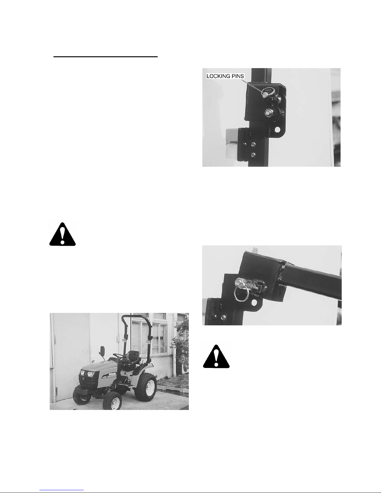
Folding the ROPS
A foldable ROPS is factory installed on your tractor.
Operate with ROPS in the raised position when-
ever possible. Use the ROPS in the folded position
only when absolutely necessary.
To fold the ROPS pull out the lockin pins, Fi ure 5,
and twist to lock in the released position. Lower
the upper section of the ROPS rearwards, releas-
in the lockin pins to anchor the ROPS firmly
once in position. To raise the ROPS reverse the
above procedure.
Figure 6 - ROPS, Folded Position
WARNING:
::
:Do not operate the tractor
with the ROPS folded as a standard
operatin mode. A folded ROPS does
not provide rollover protection.
If a seat belt is fitted, it must always be worn when
the tractor is operated with the ROPS in the raised
position. However, if the ROPS has been removed
from the tractor, or if operated in the folded position,
the seat belt should not be used.
Always pull from the tractor the drawbar. Do not
attach chains or ropes to the ROPS for pullin pur-
poses, as the tractor can tip backwards.
Figure 5 - ROPS, Raised Position

CONTROLS, INSTRUMENTS AND OPERATIONS
10
LIGHTING
HAZARD FLASHER WARNING LIGHTS AND
COMBINATION SWITCH
Your SHIBAURA tractor is equipped with hazard
li ht, Fi ure 7. The li ht switch must be turned to
the “ON” position before the hazard li ht will oper-
ate.
Figure 7 - Hazard Flasher and Turn Signals Lights
Lighting Switches
Your tractor is equipped with a combination switch
①,operatin turn si nals, hazard li hts and the
horn. The main li htin switch ②, is mounted on
the left side of the instrument console.
Figure 8 -
--
-1.Combination Switch, .Main Lighting
Switch
Combination Switch
The turn si nal li hts are activated by movin the
switch to the left or ri ht as required. The turn si -
nal switch is not self-cancelin . To operate the
hazard function, move the hazard flasher switch,
clockwise to activate all four indicator li hts.
Depressin the center button will sound the horn.
Figure 9 - Combination Switch
MAIN LIGHTING SWITCH
The main li htin switch, shown in Fi ure 10, is a
pull-push type switch. Its positions are :
1st position・・・・・・・・・・・・・・・・・・・・・・・Li hts “OFF”
2nd position・・・・・・・・・・Side and Tail Li hts “ON”
3rd position・・・・・・Side, Tail and Headli hts “ON”
(Low Beam)
4th position・・・・・・Side, Tail and Headli hts “ON”
(Hi h Beam)
Trailer Turn Indicator Light
The warnin li ht, Fi ure 10, will flash in union with
tractor/trailer turn si nals if trailer is attached.

CONTROLS, INSTRUMENTS AND OPERATIONS
11
Figure 10 – Trailer Turn indicator Light
CONTROLS, INSTRUMENTS AND OPERATIONS
12
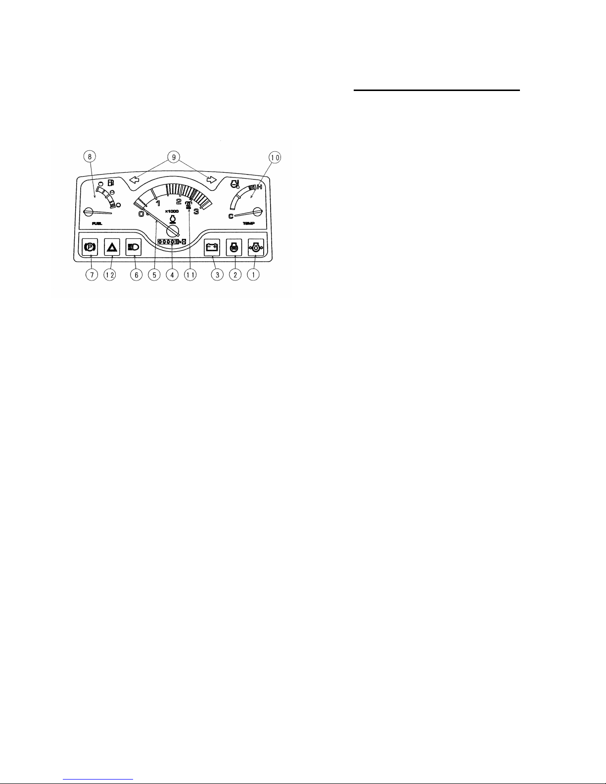
INSTRUMENT PANEL
Instrument Panel
①
①①
①
Engine Oil Pressure Warning Light - Illumi-
nates with the key switch in the “ON” or “HEAT”
positions and remains lit for a short period of
time after the en ine is started. The li ht indi-
cates oil pressure only and oes out when suf-
ficient oil pressure is present at the oil sender.
If the bulb becomes lit durin operation, stop
the tractor en ine immediately and investi ate
the cause.
②
②②
②
Cold Starting Indicator Light - Illuminates
when the key switch is turned to the “HEAT”
position. It remains lit for approximately 5 sec-
onds when the key is held in position, durin
which time the low plu s are heatin the
pre-combustion chambers.
③
③③
③
Battery Charge Warning Light - Illuminates
when the key switch is in the “ON” or “HEAT”
positions and oes out when en ine is started.
If this bulb becomes lit durin operation, it indi-
cates the char in system is not operatin
normally. As the battery can become fully dis-
char ed under these conditions, the problem
should be investi ated as soon as possible.
④
④④
④
Proof Meter - Records the hours and portions
of hours that your tractor has been operated
based on an avera e en ine speed of 1883
RPM. Use the proof meter as a uide to deter-
mine hourly service maintenance intervals.
⑤
⑤⑤
⑤
Tachometer- Re isters en ine RPM (Revolu-
tions Per Minute). The au e is marked in in-
crements of 100 and will return to zero when
the en ine is not runnin .
⑥
⑥⑥
⑥
High Beam Indicator - Illuminates when the
head-li hts are switched to main beam.
⑦
⑦⑦
⑦
Parking Brake Light - Illuminates if the parkin
brake is en a ed when the key switch is turned
from “OFF” position.
⑧
⑧⑧
⑧
Fuel Gauge - Indicates the amount of diesel
fuel when the key switch is in the “ON” or
“HEAT” positions. It will re ister empty with the
key switch in the “STOP” position.
⑨
⑨⑨
⑨
Turn Indicator Warning Lights - Flash in un-
ion with the turn si nal warnin li ht when the
level is moved to the ri ht-hand or left-hand.
⑩
⑩⑩
⑩
Temperature gauge - Indicates coolant tem-
perature. If the activated when the key switch is
turned to the “ON” or “HEAT” positions. The
au e will re ister cold with the key switch in
the “STOP” position. If the needle re isters in
the reen ran e, this indicates a normal oper-
atin temperature. If the needle moves to the
red portion of the au e, this indicates an
overheated condition. Stop the tractor en ine
immediately and investi ate the cause.
⑪
⑪⑪
⑪
Rear PTO Speed - Determined by the portion
of the needle on the tachometer. The tachome-
ter is marked to indicate 540 PTO RPM. En ine
RPM should remain close to this mark while
usin the rear PTO; runnin the en ine faster
than this results in a dan erous over speed
condition.
⑫
⑫⑫
⑫
Hazard Indicator Warning Lights - Flash in
union with the hazard warnin li ht when the
lever is moved clockwise.

CONTROLS, INSTRUMENTS AND OPERATIONS
13
KEY SWITCH
The key switch is shown in Fi ure 11.
Turnin the key to the ri ht to the “ON” position will
activate the indicator li hts and instruments.
Turnin the key further ri ht to the “HEAT” position
will active the cold-start aid.
Turnin the key to the fully clockwise to the
“START” position will start the en ine. Upon re-
lease, the key will sprin return to the “ON” posi-
tion.
To stop the en ine, turn the key to the “OFF” posi-
tion.
Figure 11- Key Switch
IMPORTANT:
::
:The key switch must remain in the
ON position while operatin the en ine. The warn-
in li hts and battery char in system will not func-
tion with the switch in the OFF position.
PRE-HEATING THE ENGINE
Your tractor has a diesel en ine. Before startin a
cold en ine, the pre-combustion chambers must be
heated.
To preheat the en ine, turn the key switch to the
“HEAT” position, Fi ure 11 and hold the key in this
position for approximately 5 seconds. The low
plu s heat the combustion chambers durin this
time, and the en ine will now be ready to start.
NOTE: When ambient temperature are colder, a
lon er preheat time may be necessary. Even after
the cold start indicator li ht has one out, the low
plu s will continue to heat if the key is held in the
“HEAT position.
WARNING:
::
:Do not use ether with the
thermostat startin aid.
STARTING THE ENGINE
The safety key switch allows activation of the start-
in motor only when:
1. The rear PTO is in the “OFF” position.
2. The mid PTO is in the “OFF” position.
3. The ran e lever in the “NEUTRAL” position.
4. The clutch pedal is fully depressed.
Always safety practices when startin your tractor.
Position the hand throttle rearward so that it is one-
fourth to one-third open when startin the tractor.
After startin return the throttle to the idle position
and allow the en ine to idle for 1 minute before op
eratin the tractor.
IMPORTANT:
::
:Do not en a e the startin motor
continuously for more than 30 seconds ; doin so
may cause startin motor failure.
NOTE:
::
:A coolant immersion heater which provides
for easier startin in temperatures below 0° F
(-17.7℃) by warmin the en ine oil and coolant,
is available as a dealer installed option.
STARTING THE TRACTOR WITH
JUMPER CABLES
WARNING:
::
:Start en ine only from
the operator’s seat.
If it is necessary to use jumper cables to start the

CONTROLS, INSTRUMENTS AND OPERATIONS
14
tractor, follow the instructions below.
1. Shield eyes.
2. Connect one end of the jumper cable to the
tractor battery positive (+) terminal and the
other to the auxiliary battery positive (+) termi-
nal. Connect one end of the other cable first to
the auxiliary battery ne ative (-) terminal, and
the other end to the tractor starter round ter-
minal. Follow the startin procedures indicated
previously above.
Idle the en ine and turn on all electrical equipment
(li hts, etc.), then disconnect the cables in reverse
order of the connectin procedure above. This will
help protect the alternator from dama e due to
extreme load chan es.
WARNING:
::
:Batteries contain sulfuric
acid and produce explosive ases.
Follow the instructions below to pre-
vent personal injury.
Wear eye and skin protection.
Keep sparks and flame away.
Always have adequate ventilation while char -
in or usin the battery.
Follow the battery manufacturer’s instruction
switch are shown on the battery.
STOPPING THE ENGINE
Pull the hand throttle fully rearward and turn the
key switch, Fi ure 11, to the “OFF” position to stop
the en ine.
IMPORTANT:
::
:Failure to turn the key switch to the
“OFF” position after the en ine has stopped will al-
low the warnin li hts to remain on, causin the
battery to dischar e.
BREAK-IN PROCEDURES
Your SHIBAURA Tractor will provide lon and
dependable service if iven proper care durin the
50 hour break-in period. Durin the first 50 hours
of operation :
1. Avoid “lu in ” the en ine. Operatin in too
hi h a ear under heavy load may cause en ine
“lu in ”, which is indicated when the en ine
will not respond to a throttle increase.
2. Use the lower ear ratios when pullin heavy
loads and avoid continuous operation at con-
stant en ine speeds. You will save fuel and
minimize en ine wear by selectin the correct
ear ratio for a particular operation. Operatin
the tractor in low ear with a li ht load and hi h
en ine speed will waste fuel.
3. Avoid prolon ed operation at either hi h or low
en ine speeds without a load on the en ine.
4. Check the instruments frequently and keep the
radiator and oil reservoirs filled to their recom-
mended levels. Daily checks include :
En ine oil level
Radiator coolant
Air cleaner
5. After the first 50 hours of use, be sure to per-
form the maintenance chart ,on Pa e 30.
WARNING:
::
:Never attempt to start the
en ine while standin beside the trac-
tor always sit in the seat when startin
the en ine.

CONTROLS, INSTRUMENTS AND OPERATIONS
15
ELECTRICAL SOCKET for Traile
r
A standard seven pin socket, Fi ure 1 , is provided
mounted on the left side of the tractor at the rear.
With reference to the picture inset, the socket
connections (as viewed from the rear of the tractor)
are as follows;
Pin No. Wire Colour Circuit
①
Green/Red L.H. Turn Si nal
② Not Used
③ Black Earth(Ground)
④ Green/White R.H. Turn Si nal
⑤ Red R.H. Parkin Li ht
⑥ Green/Purple
Stop Li hts
⑦ Red/Black L.H. Parkin Li ht
Figure 1 - Seven Pin Electrical Socket
THROTTLE CONTROLS
HAND THROTTLE AND ENGINE STOP
CON-
TROL
The hand throttle is shown in Fi ure 13. Push the
throttle rearward to increase en ine rpm. Pull the
throttle forward to decrease en ine rpm.
Figure 13 - Hand throttle
FOOT THROTTLE
(Only mechanical transmission, 9x3)
The foot throttle, shown in Fi ure 14, can be used
separately, or in conjunction with the hand throttle.
With the hand throttle control lever set at a selected
en ine rpm, the foot throttle can be used to in-
crease en ine rpm to its maximum speed.
Upon release of the foot throttle, the en ine speed
will return to the rpm at which the hand throttle has
been set, or idle if the hand throttle is not at a
pre-set position.
Figure 14 - Foot throttle and Brake Controls
CONTROLS, INSTRUMENTS AND OPERATIONS
16
BRAKE CONTROLS
BRAKE PEDALS
The brake pedals are shown in Fi ure 15. The ri ht
brake pedal is used to brake the ri ht rear wheel.
The left pedal is used to brake the left rear wheel.
Depress both pedals simultaneously to stop the
tractor.
To assist in makin sharp turns at slow speed, de-
press the ri ht or left brake pedals as required.
WARNING:
::
:When operatin the tractor
at hi h speeds, never attempt to make
sharp turns by usin the brakes.
BRAKE PEDAL LOCK
The brake pedal lock, shown in Fi ure 15, is used
to secure the brake pedals to ether.
Lock the pedals to ether whenever the tractor is
operated at hi h speeds and at any time the tractor
is used on the hi hway.
Figure 15 - Brake Pedal Locking
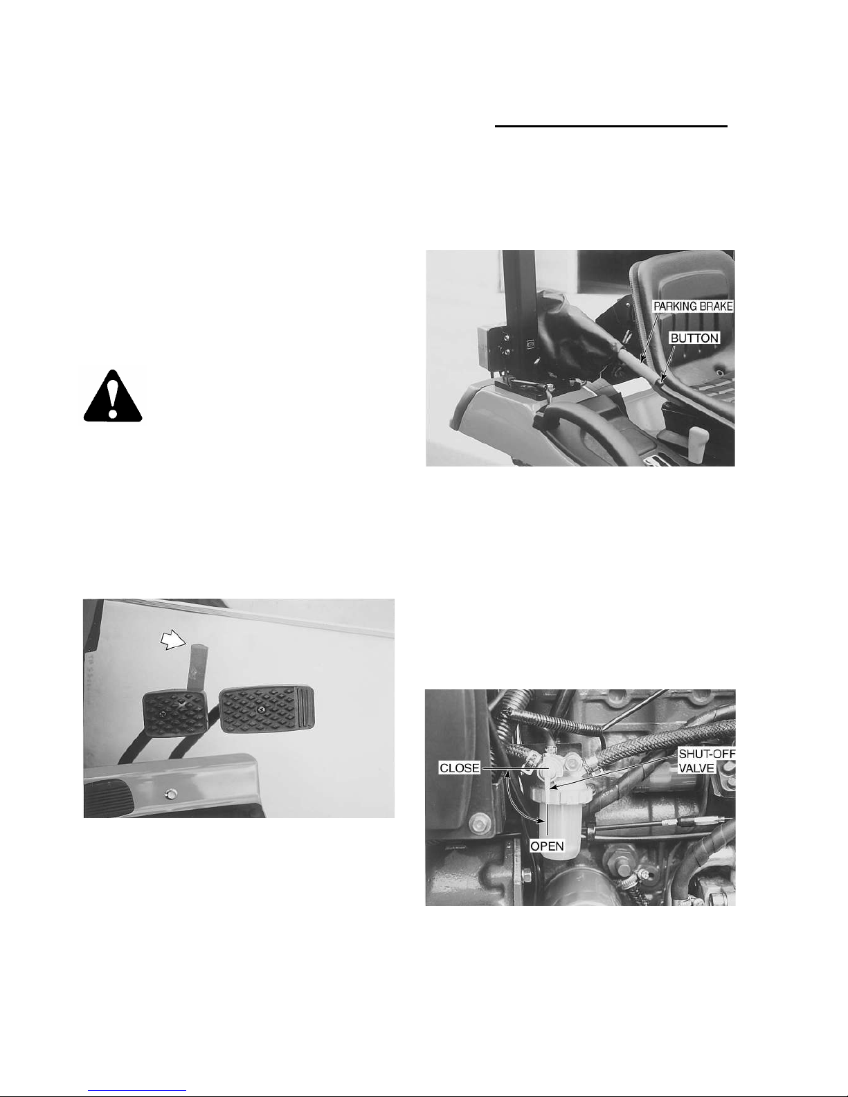
PARKING BRAKE CONTROL
The parkin brake, shown in Fi ure 16, is used for
lockin the brake pedals in the applied position.
The parkin brake should be applied whenever the
tractor is parked.
Figure 16 - Parking Brake Control
FUEL SHUTOFF VALVE
The fuel shutoff valve is shown in Fi ure 17.
To open the fuel shutoff valve, move the handle so
that it points strai ht up and down.
To close the fuel shutoff valve, move the handle to
the horizontal position. Always shut off the valve
when servicin any portion of the fuel system.
Figure17 - Fuel Shutoff Valve
CONTROLS, INSTRUMENTS AND OPERATIONS
17
FOUR-WHEEL DRIVE
The shift lever for the four-wheel drive is located
on the ri ht-hand of the seat, Fi ure 18.
Full upward, the lever disen a es the four-wheel
drive(OFF). Full downward, it en a es the four-
wheel drive(ON).
Figure18 - Four - Wheel Drive Lever
To en a e the four-wheel drive, depress the clutch
pedal fully and move the four-wheel drive lever full
downward. To disen a e, move the lever full up-
ward.
IMPORTANT :
::
:The front wheel drive should be
used when additional traction is required while op-
eratin in loose soil, wet, slippery conditions or on
slopes.
For normal operation on firm soil, level hard sur-
faces and roadin the unit at hi h speeds, front
wheel drive should be disen a ed to maximize tire
and line life and fuel economy.
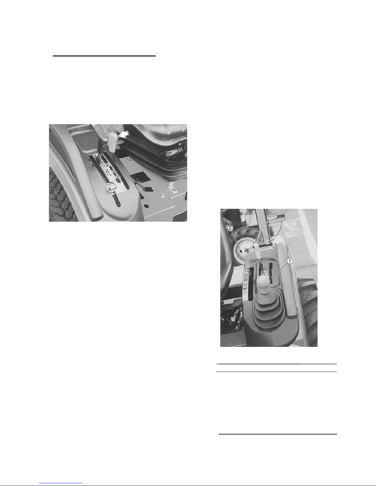
MECHANICAL TRANSMISSION MODELS
(9x3 TRANSMISSION)
TRANSMISSION GEARSHIFT LEVERS
The transmission main shift lever ① and ran e
selector lever ②, are shown in Fi ure 19.
A dia ram showin the shift pattern is on the bezel
around the earshift lever.
Three forward and one reverse speeds are pro-
vided for each of the two ran es. This provides a
total of 6 forward and 2 reverse speeds.
With a nine speed transmission the ran e lever
provides three ran es. This provides a total of 9
forward and 3 reverse speeds.
Ground speeds for the various ear ratios can be
found on pa e 56.
IMPORTANT:
::
:Do not attempt chan e ears while
the tractor is movin . The mechanical transmission
is not synchronized. The clutch pedal must be de-
pressed and tractor motion stopped to chan e ear
ratios with the main shift lever or the ran e shift
lever.
Figure 19 - Transmission Controls
SPEED RANGE MAIN
1 L 1
2 2
3 3
4 H 1
5 2
6 3
R
1
L R
R
2
H R
Other manuals for ST318
1
This manual suits for next models
2
Table of contents
Other Shibaura Tractor manuals


