Shimadzu MUX-100D User manual

Manual No.: M503-E320
Revision :B
Mobile X-ray System
MUX-100D
INSTALLATION MANUAL
Medical Systems Division
This manual is for professional service engineers.
It bears no relation to the usual operation.


TABLE OF CONTENTS
Chapter 1. Introduction
1.1 Directions for using the unit.............................................................................. 1-2
1.2 Document List.................................................................................................... 1-7
Chapter 2. Outline
2.1 Name of Each Part of the Unit........................................................................... 2-2
2.2 Name of Each Circuit Board and Layout of the Circuit Boards ....................... 2-4
2.3 Conditions for Installation (using)..................................................................... 2-6
2.4 Conditions for Transportation and Storage...................................................... 2-7
Chapter 3. Parations for installation
3.1 Tools Required for Installation..........................................................................3-2
3.2 Unpacking .......................................................................................................... 3-3
3.3 How to Open/Close the Covers......................................................................... 3-5
Chapter 4. Installation
4.1 Preinstallation Procedures................................................................................ 4-3
4.2 Installation Procedures...................................................................................... 4-4
4.3 Assemble for the CXDI-50G............................................................................... 4-5
4.4 Installation of CXDI Control S/W ....................................................................... 4-9
4.5 Setup of CXDI..................................................................................................... 4-11
4.6 Installation of CXDI Generator Communication S/W........................................ 4-16
4.7 Setup of CXDI Generator Communication S/W................................................. 4-19
4.8 Check of CXDI Generator Communication S/W................................................ 4-27
4.9 Use permission setting of external storage medium........................................ 4-27
4.10 Installation of MLT-M S/W (optional)............................................................... 4-34
4.11 Check of MLT-M S/W (optional)....................................................................... 4-35
4.12 Calibration........................................................................................................ 4-37
4.13 Selftest.............................................................................................................. 4-39
4.14 Installation of DMW-PS (optional) ................................................................... 4-39
4.15 Setup of DMW-PS (optional)............................................................................ 4-40
4.16 Check of DMW-PS function (optional)............................................................. 4-40
4.17 Setup of annotation..........................................................................................4-40
4.18 Setup of DICOM storage and print.................................................................. 4-40
4.19 Acquisition of image with phantom ................................................................ 4-41
4.20 Check of REX value.......................................................................................... 4-41
4.21 Check of DICOM storage and print function................................................... 4-41
4.22 Check of image ................................................................................................ 4-41
4.23 Check table....................................................................................................... 4-42
4.24 Removement of 50G and Power Box from MUX-100D.................................... 4-43
4.25 Packing and sending MUX-100D and 50G....................................................... 4-43
4.26 Adjustment of Image quality............................................................................ 4-43
4.27 Installing the arm cover................................................................................... 4-44

4.28 Attaching of a knob for locking collimator rotation........................................ 4-45
4.29 Changing According to the Power Supply...................................................... 4-46
4.30 Setting of XCONT............................................................................................. 4-47
4.31 Checking Performance of Each Part............................................................... 4-48
4.32 Initial setting..................................................................................................... 4-51
4.33 Attaching screw caps ...................................................................................... 4-53
4.34 Charging the Battery after installation............................................................ 4-54
4.35 Installing an apron hanger............................................................................... 4-54
4.36 Assembler Test................................................................................................ 4-54
Chapter 5. Installing the Options
5.1 Setting DIP Switches on NEXSC Board ............................................................ 5-2
5.2 Installing Remote Controller Option ................................................................. 5-3
5.3 Installing Protective Screen Option.................................................................. 5-7
5.4 Installing Dose Area Meter Option .................................................................... 5-9
Chapter 6. Specifications
6.1 Specifications.................................................................................................... 6-2
6.2 Dimensional Drawing of the Unit.......................................................................6-7
6.3 X-ray Reference Axis and Focal Spot Position.................................................6-8
6.4 Exposure Condition........................................................................................... 6-9
Appendix A. NEXSC DIP Switch Settings
A.1 Table of NEXSC DIP switch settings ................................................................ A-ii
Appendix B. Adjustment Mode
B.1 How to get into adjustment mode..................................................................... B-ii
B.2 Adjustment Mode List....................................................................................... B-iii
B.3 Adjustment of Tube Current ............................................................................. B-iv
B.4 Adjustment of the Handle ................................................................................. B-x
B.5 Adjustment of the battery voltage detection circuit......................................... B-xii
B.6 Setting Date and Time....................................................................................... B-xiii
B.7 Display and Reset of Exposure Counter .......................................................... B-xv
B.8 Display and Reset of Cumulated Mileage ....................................................... B-xvi
B.9 Display and Reset of Error Log........................................................................B-xviii
B.10 Display and Reset of Battery Charge counter................................................ B-xix
B.11 Display Running Speed................................................................................... B-xx
B.12 Battery Voltage Drop Check Mode.................................................................. B-xxii

Appendix C. Adjusting Methods
C.1 Preperation........................................................................................................ C-ii
C.2 Adjusting MUX CHARGE-04A board................................................................. C-iii
C.3 Adjusting XCONT-2002 board........................................................................... C-iv
C.4 Adjusting the battery-voltage detection circuit................................................ C-vii
C.5 Checking the X-ray exposure............................................................................ C-viii
C.6 Checking battery charging................................................................................ C-x
C.7 Volume control of a buzzer............................................................................... C-xi
C.8 Finish ................................................................................................................. C-xiii
Appendix D. Error Message List
D.1 Error Message List ............................................................................................ D-ii
Appendix E. Maintenance and Inspection
E.1 Expendable Parts List ....................................................................................... E-ii
E.2 Batteries Replacement ...................................................................................... E-iii
E.3 CPU Backup battery Replacement.................................................................... E-vii
E.4 Collimator Lamp Replacement.......................................................................... E-viii
E.5 Maintenance of rotary X-ray tube section......................................................... E-ix
E.6 Centering the Collimator and X-ray Focus....................................................... E-xiv
E.7 Adjustment of Collimator lamp voltage...............................................................E-xviii
E.8 Cleaning and disinfections................................................................................ E-xx
E.9 DR system - MUX communication .................................................................... E-xxii
E.10 How to Restration from Recovery CD..........................................................E-xxxvii
Appendix F Operation of High-Voltage Cable
F.1 Spare parts with high-voltage cable ................................................................. F-ii
F.2 Installation procedure of the high-voltage generator side plug ...................... F-iii
F.3 Installation procedure of the X-ray tube assembly side mini-plug.................. F-iv
Appendix G Super-Maintenance Function
G.1 Super-Maintenance Function............................................................................ G-ii

No Text

Mobile DaRt Installation Manual 1-1
Chapter 1
Introduction
Before installing the unit, fully grasp the contents of this Installation Manual, and
install it so that the unit may deliver its full performance and functions.
Besides, thoroughly refer to the Operation Manual and Survice Manual of this
unit.
Refer to Canon “CXDI-50G Service Manual” for installing CXDI-50G.
Chapter Contents
1.1 Directions for using the unit
Directions about safety are described in this Section. Read this
before installing the unit without fail.
1.2 Document List
1

Chapter 1 Introduction
Mobile DaRt Installation Manual
1-2
1.1 Directions for using the unit
Directions about safety are described in this Section. Read this before
installing the unit without fail.
The meanings of the following precaution and prohibition terms used
in the operation manual are defined as below:
States a direct danger that may cause death
or serious injury if it is not avoided.
States an indirect or potential danger that may
cause death or serious injury if it is not
avoided.
States a danger that may cause slight or
medium injury or may cause damage in
equipment or fire if it is not avoided.
States the information which helps to use the
system correctly.
DANGER
WARNING
CAUTION
NOTE

Chapter 1 Introduction
Mobile DaRt Installation Manual
1-3
Never Modify the Equipment!
The Drugs, Cosmetics and Medical Instruments Act of Japan makes
it compulsory that a manufacturer should apply and get approval for
partial modifications of the approved contents. Have in mind that
modifications without approval are prohibited.
Federal law restricts this device to sale by or on the order of
physician.
(This caution is the prescription language required by Federal
Regulations in U.S.A.)
Consideration for X-ray irradiation
When using X-ray equipment incorrectly, operator and patient may
have unnecessary irradiation. Be careful so that person other than
patient does not stay in the examination room when X-rays are
exposed. If it is necessary for the person other than patient to stay in
the examination room, provide sufficient shield from irradiation.
Consideration for mechanical safety
Be careful so that a part of operator’s and patient’s body −hand, foot
etc.−may not be got jammed between moving parts of the unit or
between the unit and other equipment when moving a part of the unit.
This unit is not explosion-proof. Never use this unit at a place where
flammable gas or explosive gas can be generated.
WARNING
WARNING
CAUTION
WARNING
WARNING
Chapter 1 Introduction
Mobile DaRt Installation Manual
1-4
Connect the power cord plug to a grounding 3P receptacle.
Don’t splash this equipment with water because there is a risk of electric
shock. And to clean the equipment, wipe the surface of the equipment
with the clothes soaked in antiseptic solution. (MedicalAlcohol)
When operating the arm of the unit, make sure to place the unit on
the floor whose inclination is 5 degrees or less. Otherwise, the unit
may fall down if the arm position is not appropriate.
Never drive the unit in a place where vibration will occur such as a
road outdoor, a bumpy place or steep slope. Never stop the unit on a
slope.
Even if the bumper switch on the front of the unit contacts an
obstacle while moving, obstacles are not detected if the force applied
to the bumper switch is 2 kg or smaller. Watch out for obstacles in
front while moving.
This unit is driven by a built-in battery.
Some wires are always exposed to 240 V of power voltage from the
battery even when the key switch, switch for activating the
emergency brake release function, or main circuit breaker is turned
off. Watch out for an electric shock during operation.
Wires that always have power voltage are red.
The software (Operating system, OS) installed in this device runs
under Windows XP. Do not change any of the OS settings. If the OS
settings are changed, device operation after those changes is not
guaranteed.
CAUTION
WARNING
WARNING
WARNING
CAUTION
CAUTION
CAUTION
Chapter 1 Introduction
Mobile DaRt Installation Manual
1-5
Accidents due to operation errors or unforeseen causes can result in
deleting or damage to stored hard disk data (i.e. images and data).
Thus, be sure to backup (archive) important data to an external file
system, or print out the file data. Additionally, since external file
systems also have the danger of being damaged, be sure to perform
multiple backups to prevent data deletion, damage or loss.
Also, Shimadzu Corporation assumes no liability for the loss or
damage to any customer data.
Do not turn the main power breaker OFF during the normal operation
of this device. Turning the breaker OFF can result in device damage,
an operation error or data loss or damage.
Be sure to follow the procedures described in this manual to start or
stop this product. Also, do not turn the main power breaker OFF
during normal operation of this device, and especially during the
operation of this device’s internal magnetic disk. Turning the breaker
OFF can result in device damage, an operation error or data loss or
damage.
Do not connect peripheral units that are not compliant with safety
regulations (comform to IEC60601-1) to this device’s connectors
(LAN port, USB port, etc.). Connecting one of these units can result
in device damage, operation error, smoking, overheating, electric
shock, data loss or damage.
Shimadzu Corporation assumes no liability in the event of data
deletion or damage, device accident or damage, or loss occurs due
to the installation of software or the connection of a peripheral unit
that is not designated by Shimadzu Corporation.
CAUTION
CAUTION
CAUTION
CAUTION
CAUTION

Chapter 1 Introduction
Mobile DaRt Installation Manual
1-6
Shimadzu Corporation assumes no liability in the event of data
deletion or damage, device accident or damage, or loss occurs due
to the modification or deletion of this software’s setting files
(Autoexec.bat, config.sys, etc.) and DR system software files.
Shimadzu Corporation assumes no liability in the event of device
data deletion, damage or loss, due to an operation error or sudden
accident.
Software License Agreement
The software used in this product is copyrighted by Shimadzu Corporation,
who possesses all rights, including sublicenses for those rights received (for
copyrights, etc.) held by third parties.
The Customer and Shimadzu have the following agreement concerning the
usage of this software.
1. Application
i. This software (hereafter “the software”) includes all software programs,
additional data and the Installation Guide used by this device.
2. Rights
i. The Customer is allowed to use the software with a single (1) device.
ii. If the customer wishes to transfer all of their rights to the software, the
creation of a copy of the software is prohibited and the software in its
entirety (the program, and all its media and user documentation,
including this Installation Guide) must be transferred. The assignor is
then assumed to be legally bound by the terms and conditions of this
agreement.
iii. The Customer shall not, in all or in part, loan, lease, sub-license,
reproduce, modify, edit, reverse-engineer, reverse-compile, or
reverse-assemble the software. These actions also are not allowed by
third parties.
3. Copyright
i. Shimadzu Corporation retains all the software’s ownership, copyright, and
software-related intellectual property rights.
CAUTION
CAUTION

Chapter 1 Introduction
Mobile DaRt Installation Manual
1-7
1.2 Document List
If necessary, the following documents can be obtained. Contact the responsible service shop of Shimadzu
Corporation.
Document Document Number
MUX-100D Operation Manual M503-E017
MUX-100D Installation Manual M503-E320
X-ray tube assembly Operation Manual M535-E219
MUX-100D Parts List M503-4007
MUX-100D Connection Diagram There is no document
number.

Chapter 1 Introduction
Mobile DaRt Installation Manual
1-8
No Text

Mobile DaRt Installation Manual
2-1
Chapter 2
Outline
This chapter describes the outline and features of "Mobile DaRt ".
Read this before installing the unit.
Chapter Contents
2.1 Name of Each Part of the Unit
The name of each part of the unit is described in this Section.
2.2 Name of Each Circuit Board and Layout of the Circuit Boards
The name of each circuit board and layout of the main circuit
boards installed in the unit are described in this Section.
2.3 Conditions for Installation (using)
Basic specifications are described.
2.4 Conditions for Transportation and Storage
Basic specifications are described.
2

Chapter 2 Outline
Mobile DaRt Installation Manual
2-2
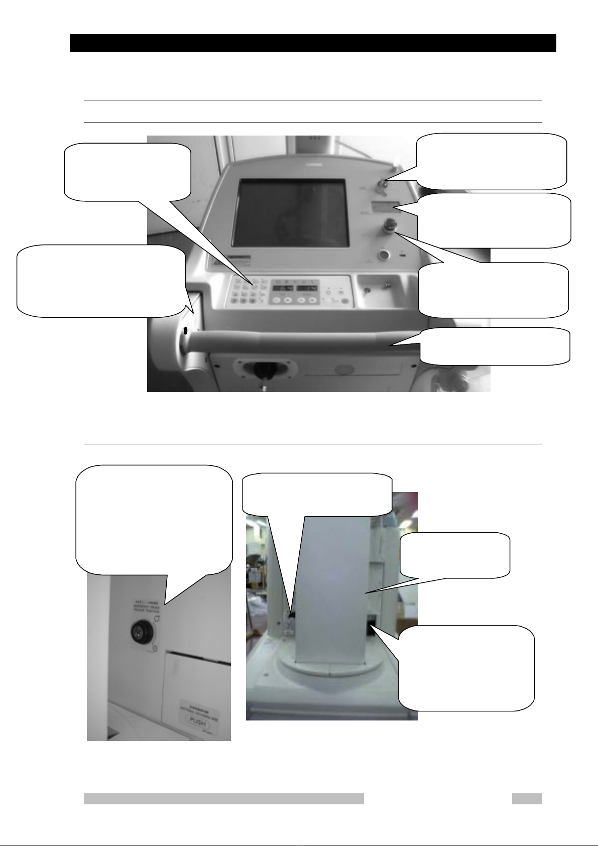
2.1 Name of Each Part of the Unit
Appearance
Arm section:
Holds the tube section. It
can slide vertically on the
support stand and the ar
m
itself can stretch in the
horizontal direction.
X-ray tube unit:
The combination of X-ray tube and
collimator can turn around the axis of
X-ray focus. This makes positioning
and adjustment of the irradiation field
and small movement of the unit.
Hand switch:
The switch to make X-ra
y
exposures
Support Stand:
Holds the tube section
and arm. It can tur
n
itself.
Bumper switch section:
Stops the unit in the event of a
collision.
Chapter 2 Outline
Mobile DaRt Installation Manual
2-3
Operating section
Power plug and main circuit breaker
Key switch:
Turns on/off power for the uni
t
with this key operation.
Battery checker:
Indicates remaining charge of the
battery.
Emergency stop switch:
Used to stop the motor in the
event of an emergency.
Running handle:
The handle to drive the unit.
X-ray control panel:
Refer to Operation
Manual M503-E017.
Emergency brake release switch
Used to release brake in the even
t
of a problem with the runnin
g
system.
P
Main circuit breaker:
Turnin
g
off this breaker
cuts off
p
ower for the
whole unit. The lid can be
o
p
ened b
y
p
ressin
g
and
releasin
g
it.
ower plug:
Used to char
g
e the batter
y
.
Emergency brake
active key switch:
Switch for activating the
emergency brake release
function:
In the trouble of the runnin
g
s
y
stem, the brake release function
for the emer
g
enc
y
is
p
ut into the
state which can be o
p
erated b
y
the ke
y
o
p
eration.

Chapter 2 Outline
Mobile DaRt Installation Manual
2-4
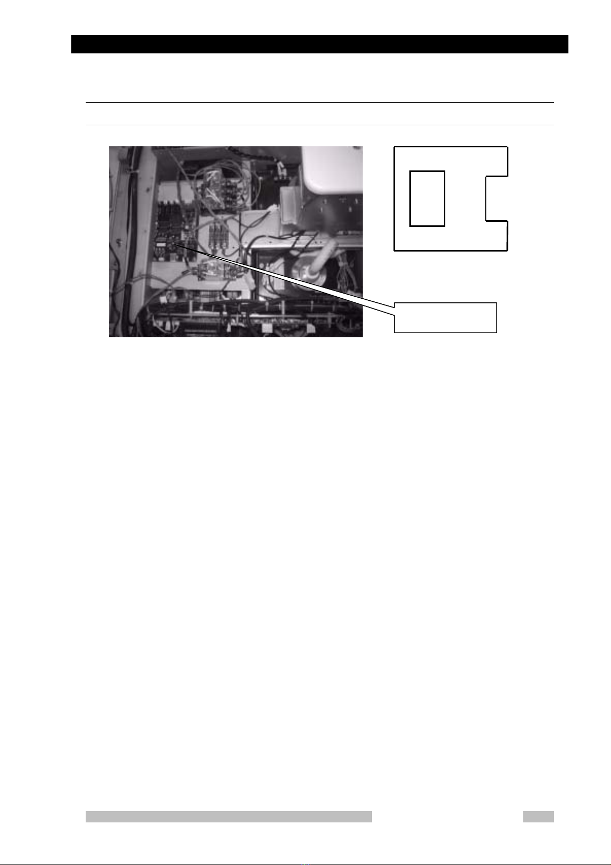
2.2 Name of Each Circuit Board and Layout of the
Circuit Boards
Right side of the unit
Left side of the unit
X CONT-2002
NEXSC CPU
MU-Driver-2
Breaker NFB1
Under side is ON
Bus Extender
MUX
C
h
a
r
ge
0
4B
MUX-LC1B
Inverter Unit
C1
MUX
Charge 04A
MUX
Power 99
Chapter 2 Outline
Mobile DaRt Installation Manual
2-5
Top of the unit (battery)
Power 100D
Power
100D
Power 100D

Chapter 2 Outline
Mobile DaRt Installation Manual
2-6
2.3 Conditions for Installation (using)
Use environment
Ambient temperature :-10℃- 40℃
Relative humidity :30% - 60% (no dew condensation)
Atmospheric pressure :700 hPa - 1060 hPa
As for charge the battery, do it in the use environment.
Do not do it in the storage environment.
Storage environment ( without a package for transport and storage )
Ambient temperature :-10℃~ 40℃
elative humidity :30% ~ 60% (no dew condensation)
Atmospheric pressure :700 hPa ~ 1060 hPa
Power supply
AC power
System :Single phase AC
Frequency :50/60 Hz
Standard voltages :100, 110, 120, 200, 220, 230, 240 V
Voltage variation range :±10% of standard voltages
Supply capacity :1kVA
Supply Impedance :100, 110, 120 V : 1.0Ωor less
200, 220, 230, 240 V : 4.0Ωor less
Earth
Earth terminal :Earth resistance of 100Ωor less
Additional earth terminal :Earth resistance of 100Ωor less
CAUTION
Other manuals for MUX-100D
2
This manual suits for next models
3
Table of contents
Other Shimadzu Medical Equipment manuals


Popular Medical Equipment manuals by other brands


3A HEALTH CARE
3A HEALTH CARE MINIASPEED Battery Evo Plus instruction manual

Capintec
Capintec CAPTUS 3000 owner's manual

MIMSAL
MIMSAL LUPA LED H.F user manual

Sunrise Medical
Sunrise Medical Guardian IC-5142 User instructions

Albrecht
Albrecht HYPEX LITE User instructions

ResMed
ResMed VPAP ST Information guide


