Shimano Steps E6000 Series User manual

(English)
DM-SP0001-03
Dealer's Manual
E6000 Series
SC-E6000
SW-E6000
FC-E6000
SM-CRE60
DU-E6000
DU-E6001
SM-DUE01
BT-E6000
BT-E6010
SM-BME60
SM-BME61
SM-BCE60
TL-FC38

2
CONTENTS
IMPORTANT NOTICE.............................................................................................. 4
TO ENSURE SAFETY............................................................................................... 5
Installation............................................................................................................. 9
Names of parts ...........................................................................................................................................10
Product specifications ................................................................................................................................11
Installing the cycle computer ....................................................................................................................12
Installing and removing the cycle computer ............................................................................................13
Adjusting the angle of the cycle computer ..............................................................................................13
Using the cable band to attach the assist switch to the handlebar........................................................14
Installing the assist switch .........................................................................................................................14
Installing the battery mount .....................................................................................................................15
Installing the battery .................................................................................................................................17
Installing the speed sensor ........................................................................................................................18
Mounting the magnet ...............................................................................................................................19
Installing and wiring the drive unit................................................................... 21
Installing the drive unit .............................................................................................................................21
Drive unit wiring diagram .........................................................................................................................21
Connecting the power cord.......................................................................................................................22
Installing the ferrite core (DU-E6001).......................................................................................................23
Connecting the electric wire .....................................................................................................................24
Connecting the assist switch and drive unit to the cycle computer........................................................24
Connecting the speed sensor to the drive unit ........................................................................................25
Connecting the light adapter to the drive unit .......................................................................................25
Installing the ferrite core (MU-S705) ........................................................................................................27
Installing the crank and front chainring...................................................................................................28
Adjustment of the chain tension ..............................................................................................................29

3
Charging the battery .......................................................................................... 31
Introduction................................................................................................................................................31
Proper use of the battery ..........................................................................................................................31
Charging the Battery .................................................................................................................................31
Battery level indicator................................................................................................................................33
Battery level and error indication.............................................................................................................34
Cycle Computer Display and Setting................................................................. 36
Names and functions of the parts of the assist switch ............................................................................36
Basic screen display of the cycle computer...............................................................................................36
Launching and exiting the Setting menu .................................................................................................40
Changing the settings................................................................................................................................41
Error messages on the cycle computer .....................................................................................................48
Connection and communication with the PC ................................................... 51
Settings customizable in E-tube Project ...................................................................................................52
Connecting to the PC.................................................................................................................................53
MAINTENANCE.................................................................................................... 56
Replacing the front chainring ...................................................................................................................56
4
IMPORTANT NOTICE
IMPORTANT NOTICE
•
This dealer’s manual is intended primarily for use by professional bicycle mechanics.
Users who are not professionally trained for bicycle assembly should not attempt to install the components themselves using the dealer’s manuals.
If any part of the information on the manual is unclear to you, do not proceed with the installation. Instead, contact your place of purchase or a local
bicycle dealer for their assistance.
•
Make sure to read all instruction manuals included with the product.
•
Do not disassemble or modify the product other than as stated in the information contained in this dealer’s manual.
•
All dealer’s manuals and instruction manuals can be viewed on-line on our website (http://si.shimano.com).
•
Please observe the appropriate rules and regulations of the country, state or region in which you conduct your business as a dealer.
For safety, be sure to read this dealer’s manual thoroughly before use, and follow it for correct use.
The following instructions must be observed at all times in order to prevent personal injury and physical damage to equipment and surroundings.
The instructions are classified according to the degree of danger or damage which may occur if the product is used incorrectly.
DANGER
Failure to follow the instructions will result in death or serious injury.
WARNING
Failure to follow the instructions could result in death or serious injury.
CAUTION
Failure to follow the instructions could cause personal injury or physical damage to equipment and surroundings.
5
TO ENSURE SAFETY
TO ENSURE SAFETY
DANGER
Be sure to also inform users of the following:
Handling the battery
•
Do not deform, modify, disassemble or apply solder directly to the battery. Doing so may cause leakage, overheating, bursting, or ignition of the
battery.
•
Do not leave the battery near sources of heat such as heaters. Do not heat the battery or throw it into a fire. Doing so may cause bursting or ignition
of the battery.
•
Do not subject the battery to strong shocks or throw it. If this is not observed, overheating, bursting, or fire may occur.
•
Do not place the battery into fresh water or sea water, and do not allow the battery terminals to get wet. Doing so may cause overheating, bursting,
or ignition of the battery.
•
Use the battery and charger combination specified by the company for charging and follow the charging conditions specified by the company. Not
doing so may cause overheating, bursting, or ignition of the battery.
WARNING
•
Be sure to follow the instructions provided in the manuals when installing the product.
It is recommended that you use only genuine Shimano parts. If parts such as bolts and nuts become loose or damaged, the bicycle may suddenly fall
over, which may cause serious injury. In addition, if adjustments are not carried out correctly, problems may occur, and the bicycle may suddenly fall
over, which may cause serious injury.
•
Be sure to wear safety glasses or goggles to protect your eyes while performing maintenance tasks such as replacing parts.
•
For information on products not explained in this manual, refer to the manuals provided with each product.
•
After reading the dealer's manual thoroughly, keep it in a safe place for later reference.
Be sure to also inform users of the following:
•
Be careful not to let yourself be distracted by the cycle computer display while riding the bicycle. Otherwise, you may fall off the bicycle.
•
Before riding, check that the wheels are secured. Otherwise, you may fall off the bicycle and be seriously injured.
•
Be sufficiently familiar with how to start the power assisted bicycle before riding on busy streets. Otherwise, you may start the bicycle abruptly and
have an accident.
•
Make sure that the light is on during night riding.

6
TO ENSURE SAFETY
Lithium Ion Battery
•
If any liquid leaking from the battery gets into your eyes, immediately wash the affected area thoroughly with clean water such as tap water without
rubbing your eyes, and seek medical advice immediately. If this is not done, the battery liquid may damage your eyes.
•
Do not recharge the battery in places with high humidity or outdoors. If this is not observed, electric shocks may result.
•
Do not insert or remove the plug while it is wet. If this is not observed, electric shocks may result. If there is water leaking out of the plug, dry it
thoroughly before inserting it.
•
If the battery does not become fully charged after 6 hours of charging, immediately unplug the battery from the outlet to stop charging, and contact
the place of purchase. Not doing so may cause overheating, bursting, or ignition of the battery.
•
Do not use the battery if it has any noticeable scratches or other external damage. Doing so may cause bursting, overheating or problems with
operation.
•
The operating temperature ranges for the battery are given below. Do not use the battery in temperatures outside these ranges. If the battery is used
or stored in temperatures outside these ranges, fire, injury or problems with operation may occur.
1. During discharge: –10 °C - 50 °C
2. During charging: 0 °C - 40 °C
Items related to installation to and maintenance of the bicycle
•
Be sure to remove the battery before wiring or attaching parts to the bicycle. Otherwise, an electric shock may result.
•
Be sure to follow the instructions provided in the manuals when installing the product. It is recommended that you use only genuine Shimano parts. If
bolts and nuts become loose or the product is damaged, the bicycle may suddenly fall over, resulting in a serious injury.
•
Maintenance interval depends on the usage and riding circumstances. Clean regularly the chain with an appropriate chain cleaner. Never use alkali
based or acid based solvents such as rust cleaners. If those solvent be used chain might break and cause serious injury.
CAUTION
Be sure to also inform users of the following:
•
Observe the instructions in the user's manual for the bicycle, in order to ride safely.
•
Periodically check the battery charger, particularly its cord, plug, and case, for any damage. If the battery charger is damaged, do not use it until it is
repaired.
•
Use the product under the direction of a safety supervisor or the directions for use. Do not allow physically, sensory, or mentally impaired persons,
inexperienced persons, or persons with no required knowledge including children to use this instrument.
•
Do not allow children to play near the product.
•
If any malfunction or trouble occurs, consult the dealer nearest you.
•
Never modify the system. This may cause a malfunction in the system.
Lithium Ion Battery
•
Do not leave the battery in a place exposed to direct sunlight, inside a vehicle on a hot day, or other hot places. This may result in battery leakage.
•
If any leaked fluid gets on your skin or clothes, wash it off immediately with clean water. Otherwise, the leaked fluid may damage your skin.
•
Store the battery in a safe place out of the reach of infants and pets.
7
TO ENSURE SAFETY
Note
Be sure to also inform users of the following:
•
Be sure to attach dummy plugs to any unused ports.
•
For installation and adjustment of the product, consult a dealer.
•
The units are designed to be fully waterproof to withstand wet weather riding conditions. However, do not deliberately place them into water.
•
Do not clean the bicycle in a high-pressure car wash. If water gets into any of the components, operating problems or rusting may result.
•
Handle the components carefully, and avoid subjecting them to any strong shocks.
•
Although the bicycle still functions as a normal bicycle even when the battery is removed, the light does not turn on if it is connected to the electric
power system. Be aware that using the bicycle under these conditions will be considered non-observance of the road traffic laws in Germany.
•
When carrying the bicycle in a car, remove the battery from the bicycle and place it on a stable surface in the car.
•
Before connecting the battery, make sure that there is no water collecting in the connector where the battery will be connected.
•
Some of the important information in this dealer's manual can also be found on the device labels.
•
The number found on the battery key is necessary when purchasing spare keys. Store it carefully.
•
Use a damp cloth, with the water well wrung out, when cleaning the battery and plastic cover.
•
If you have any questions about the use and maintenance of the product, consult the dealer where you made the purchase.
•
Products are not guaranteed against natural wear and deterioration from normal use and aging.
•
For maximum performance we highly recommend Shimano lubricants and maintenance products.
•
Contact the place of purchase for updates of the component software. The most up-to-date information is available on the Shimano website. For
details, refer to the "Connection and communication with the PC" section.
Lithium Ion Battery
Disposal information for countries outside the European Union
This symbol is only valid within the European Union.
Follow local regulations when disposing of used batteries. If you are not sure, consult the place of
purchase or a bicycle dealer.
Items related to installation to and maintenance of the bicycle
•
Incorrect adjustment, such as excessive tightening of the chain, may cause the product to fail to provide an appropriate level of assistance.
•
Do not disassemble the product. Disassembling it may cause injury to persons.
•
Do not use thinner or other solvents to clean any of the components. Such substances may damage the surfaces.
•
You should periodically wash the chainrings in a neutral detergent. In addition, cleaning the chain with neutral detergent and lubricating it can be an
effective way of extending the useful life of the chainrings and the chain.
The actual product may differ from the illustration because this manual is intended chiefly to explain the procedures for using
the product.

Installation
9
Installation
Installation
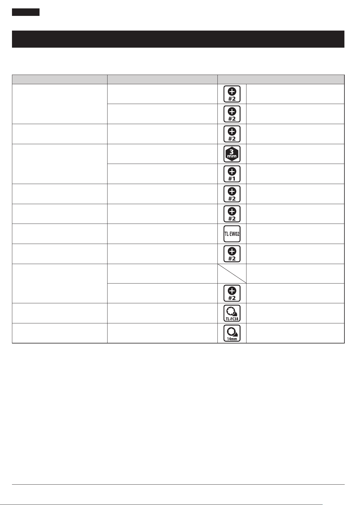
List of tools to be used
The following tools are required to assemble the product.
Component Where to use Tool
Cycle computers
Handlebar fixing bolt Screwdriver #2
Angle adjustment screw Screwdriver #2
Assist switch Fixing bolt Screwdriver #2
Battery Mount
(SM-BME61)
Key unit
Mount lower case 3 mm Allen key
Key unit cover
Mount upper case Screwdriver #1
Speed sensor Speed sensor fixing bolt Screwdriver #2
Magnet unit Mounting screw Screwdriver #2
Electric wire Connector TL-EW02
Light adapter Unit fixing screw Screwdriver #2
Drive Unit
Frame installation bolt M8 bolt and nut compatible*
Cover fixing bolt (M3) Screwdriver #2
Front chainring Lock ring TL-FC32 / 36+TL-FC38
Crank arm Crank installation bolt 14 mm socket wrench
* For information on compatible tools, contact a manufacturer of completed bicycles.
Installation
Names of parts
10
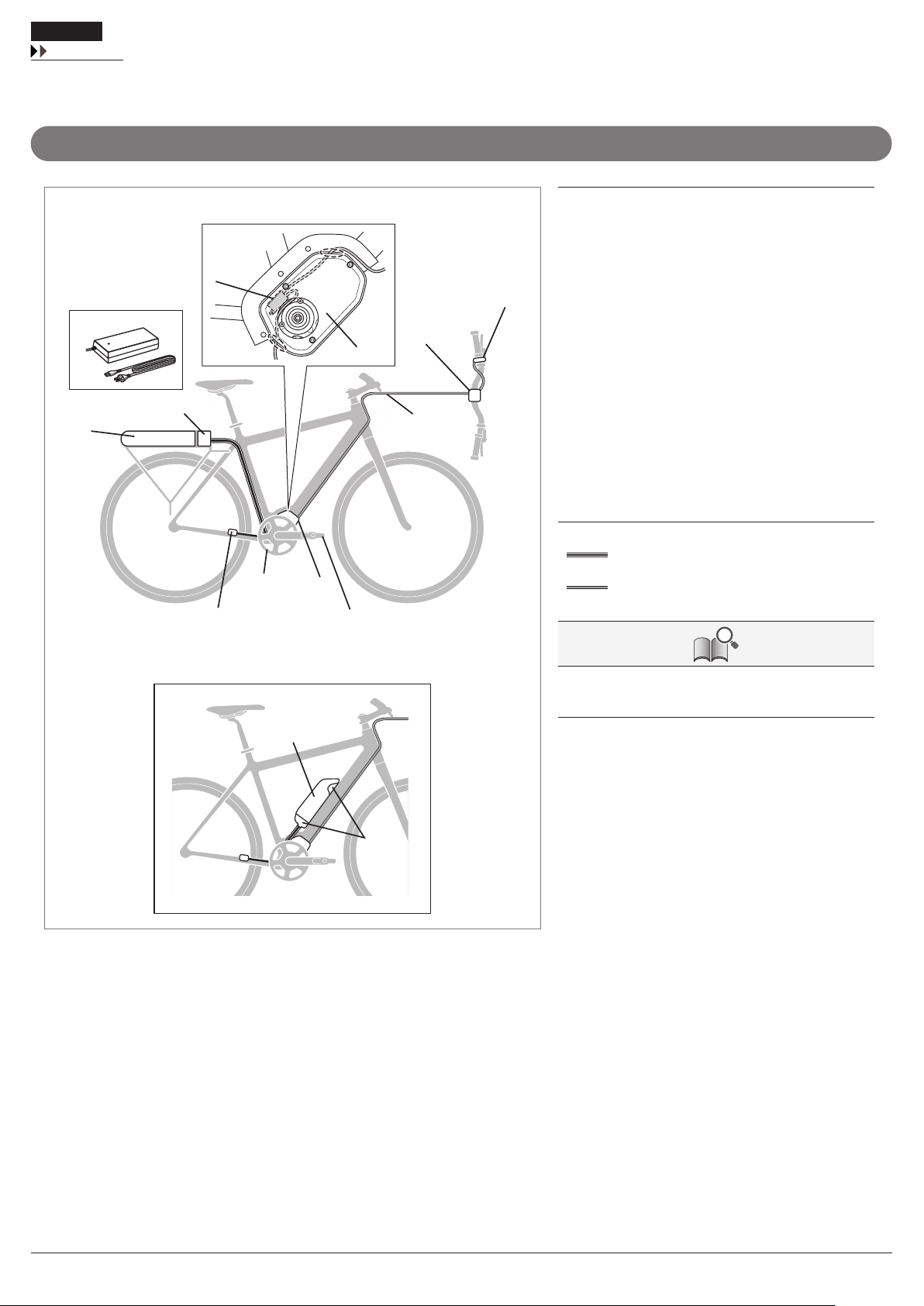
Names of parts
In the case of mechanical gear shifting
<BT-E6000 / SM-BME60> (A) Cycle computer SC-E6000
(B) Assist switch SW-E6000
(C) Front chainring SM-CRE60
(D) Crank arm FC-E6000
(E) Drive Unit DU-E6000/
E6001
(F) Speed sensor DU-E6000/
E6001
(G) Battery BT-E6000
(H) Battery Mount SM-BME60
(I) Battery charger SM-BCE60
(J) Light adapter SM-DUE01
(K) Drive unit cover SM-DUE60
(L) Battery BT-E6010
(M) Battery Mount SM-BME61
Wire harness
E-tube
Maximum cable length (EW-SD50)
(a) ≤ 1600 mm
(A)
(a)
(B)
(F)
(C)
(H)
(G)
(E)
(D)
(I)
(J)
(K)
<BT-E6010 / SM-BME61>
(L)
(M)

Installation
Product specifications
11
In the case of power gear shifting
(B)
(A)
(C)
(a)
(b)
(A) Assist/Shift switch SW-E6000
(B) Motor unit MU-S705
(C) Internal geared hub SG-C6060
SG-S705
SG-S505
Wire harness
E-tube
For information on how to install MU-S705, refer to
"Installing the monitor unit to the hub (MU-S705)" in the
dealer's manual for the ALFINE S705 series.
Maximum cable length (EW-SD50)
(a) ≤ 1600 mm
(b) ≤ 700 mm
Product specifications
Operating temperature range:
During discharge -10 – 50 °C Nominal capacity 11.6 Ah
Operating temperature range:
During charging 0 – 40 °C Rated voltage 36 V DC
Storage temperature -20 – 70 °C Drive unit type Midship
Storage temperature (Battery) -20 – 60 °C Motor type Brush-less DC
Charging voltage 100 – 240 V AC Rated drive unit power 250W
Charging time About 4 hours Maximum drive unit power 500W
Battery type Lithium Ion Battery

Installation
Installing the cycle computer
12
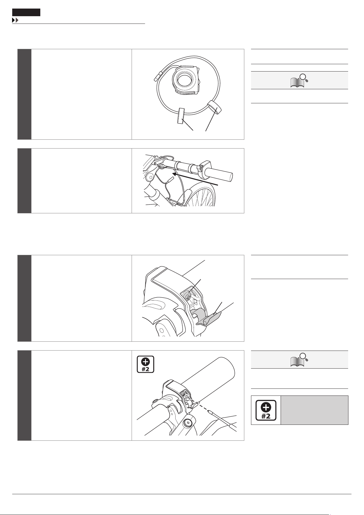
Installing the cycle computer
1Open the clamp (B) and attach it to the handlebar.
2
Attach and tighten the handlebar fixing
bolt (A) with a screwdriver.
(A)
(B)
(C)
(A) Handlebar fixing bolt
(B) Clamp
(C) Adapter
Handlebar compatibility table
øA øB-øA Adapter Fixing bolt
ø23.4-ø24 0-1.1 X 15.5mm
ø24-ø25.5 0-1.1 X 20mm
ø31.3-ø31.9 0-0.6 - 20mm
*X: OK
Handlebar
øA
øB
25
30
When removing the cycle computer, reverse
the procedure.
Tightening torque:
1 N·m
{9 in. lbs.}

Installation
Installing and removing the cycle computer
13
Installing and removing the cycle computer
1
Slide the cycle computer (A) into the
bracket (B) as shown in the illustration.
Insert it firmly until you hear it click. (A)
(B)
(A) Cycle computer
(B) Bracket
2
To remove the cycle computer, slide it
while pushing the bracket lever (C).(C) (C) Lever
NOTE
If the cycle computer is not in the correct
place, the assist function will not operate
normally.
Adjusting the angle of the cycle computer
Loosen the angle adjustment screw (A) with a
screwdriver. Adjust the angle of the cycle
computer to make it easier to see while riding.
After determining the angle, tighten the screw
to the designated torque.
(A)
(A) Angle adjustment screw
Tightening torque:
0.5 N·m
{4.4 in. lbs.}
Installation
Using the cable band to attach the assist switch to the handlebar
14
Using the cable band to attach the assist switch to the handlebar
1
Temporarily attach the cable band (A) to
the assist switch. Adjust the cable band
according to the length of the
handlebar.
(A)
(A) Cable band
The cable band is included in SW-E6000.
2
Attach the assist switch mounted with
the cable band to the handlebar.
Installing the assist switch
1
Attach the assist switch to a ɸ 22.2
handlebar with the electric wire routed
under the switch and open the fixing
bolt cover (A).
(B)
(A)
(A) Fixing bolt cover
(B) Fixing bolt
2
Tighten the fixing bolt (B) with a
screwdriver (#2).
When removing the cycle computer, reverse
the procedure.
Tightening torque:
1.5 N·m
{14 in. lbs.}

Installation
Installing the battery mount
15
Example of routing the electric wire
Example 1: Secure the electric wire of the
assist switch (A) to the handlebar using the
cable band (B). Wind the excess electric wire
around the area between the cycle computer
(C) and stem (D), then connect the wire to the
cycle computer.
(D)
(B) (C)(A) (A) Assist switch
(B) Cable band
(C) Cycle computer
(D) Stem
Example 2: Secure the electric wire of the
assist switch to the handlebar using the cable
band. Bind the electric wire of the assist switch
and that of the cycle computer (E) to the brake
outer casing using (F) the band (G) and connect
the electric wire of the assist switch to the cycle
computer.
(E)
(F)
(G)
(E) Electric wire of the cycle computer
(F) Brake outer casing
(G) Band
The band is included in SC-E6000.
Installing the battery mount
SM-BME60
Align the mounting holes in the carrier with
those in the battery mount. Insert hexagon
socket head cap screws (A) into the upper part
of the battery mount and tighten it to the
carrier.
(A) (A) Hexagon socket head cap screw
(M5)
Bolts and nuts are not included with Shimano
products. Use those supplied by the
manufacturer.
For information on the tightening torques,
contact the manufacturer of the carrier.

Installation
Installing the battery mount
16
SM-BME61
1
Attach the mount lower case (E) to the
mounting holes in the frame, insert the
mount fixing bolts (C) into the washers
(D), and secure the case using the bolts.
Then, temporarily attach the key unit (B)
with the key unit fixing bolts (A).
(A)
(D)
(B)
(E)
(C)
(A) Key unit fixing bolt (M5)
(B) Key unit
(C) Mount fixing bolt (M5)
(D) Washer
(E) Mount lower case
Tightening torque:
3 N·m
{27 in. lbs.}
2
Adjust the position of the key unit to
allow a clearance of 223 mm between (a)
and (b) shown in the illustration.
Temporarily attach the key unit cover
and perform adjustment to make sure
that the battery can be smoothly
connected and disconnected and no
noise will be produced due to looseness
during traveling. Then, fully tighten the
key unit fixing bolts. 223mm
(a)
(b)
Tightening torque:
3 N·m
{27 in. lbs.}
3
Fully tighten the key unit cover fixing
bolts (J) to attach the key unit cover (I).
Insert the plug (F) into the mount lower
case. Insert the plug between the mount
upper case (G), and secure them using
the mount upper case fixing bolts (H).
(G)
(H)
(F)
(J)
(I)
(F) Plug
(G) Mount upper case
(H) Mount upper case fixing bolt (M3)
(I) Key unit cover
(J) Key unit cover fixing bolt
(M4)
Tightening torque:
0.6 N·m
{5.3 in. lbs.}
Installation
Installing the battery
17
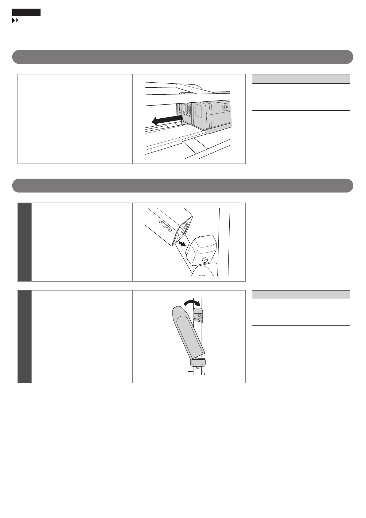
Installing the battery
BT-E6000 / SM-BME60
Set the battery on the mount rail from behind
and slide it forward.
Push it firmly into place.
NOTE
To prevent the battery from falling off, check
to see that the battery is locked after
installation.
BT-E6010 / SM-BME61
1
Align the indentation in the bottom of
the battery with the protrusion on the
mount and insert the battery.
2
Slide the battery to the right starting
from the point where it is inserted. Push
it firmly into place.
NOTE
To prevent the battery from falling off, check
to see that the battery is locked after
installation.
Installation
Installing the speed sensor
18
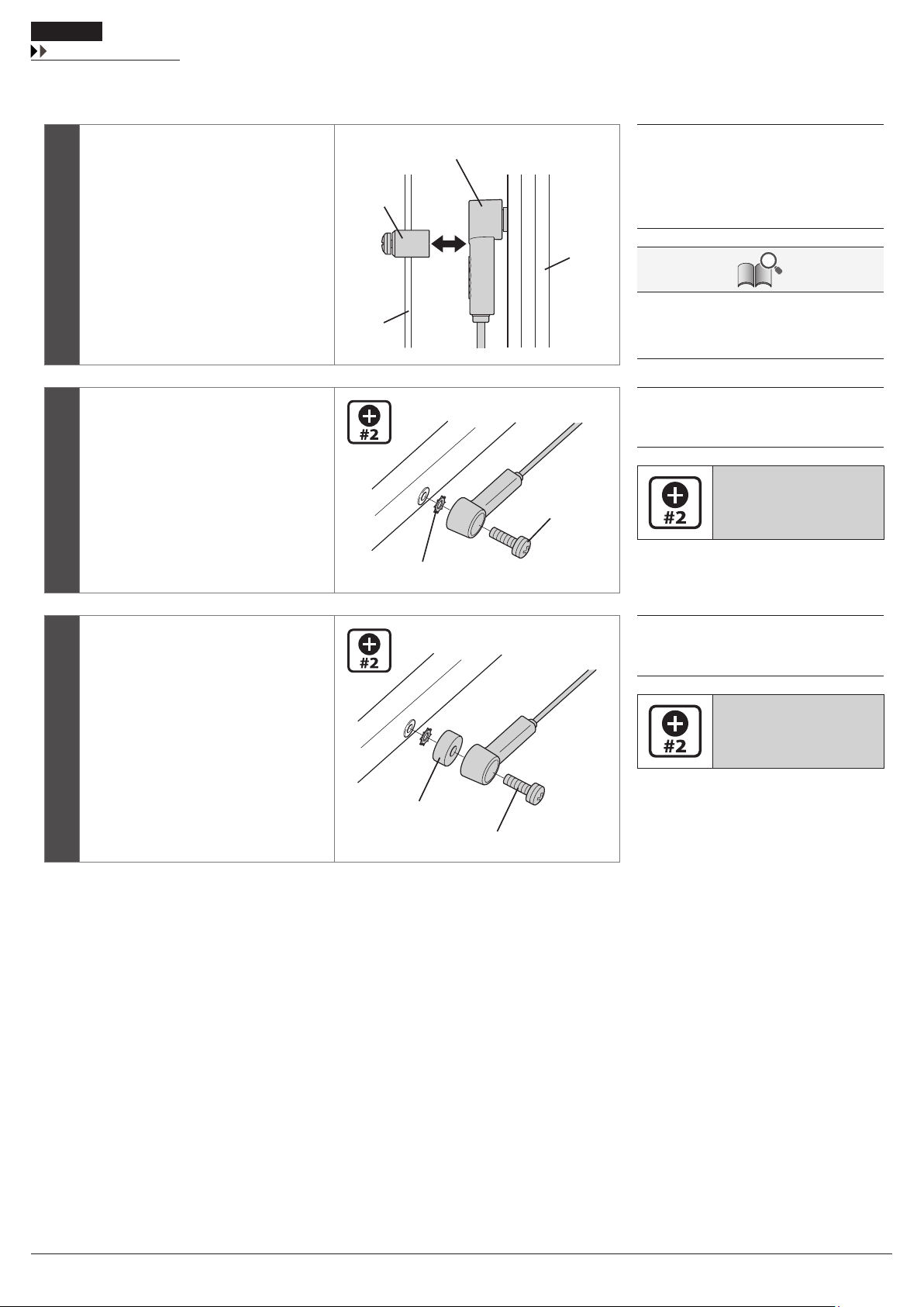
Installing the speed sensor
1
Before installing the speed sensor (A),
check that the clearance (a) between the
speed sensor and the magnet unit (B)
will be within 3 to 17 mm.
(A)
(a)
(C)
(D)
(B)
(A) Speed sensor
(B) Magnet unit
(C) Spoke
(D) Chain stay
When checking the clearance is within 17 mm,
take wheel truing, frame distortion, etc. into
account.
2
If the clearance is within the designated
range, place the toothed washer (E)
between the speed sensor and the chain
stay, then attach the speed sensor fixing
bolt (F).
(E)
(F)
(E) Toothed washer
(F) Speed sensor fixing bolt (16 mm)
Tightening torque:
1.5 - 2 N·m
{14 - 17 in. lbs.}
3
If the clearance exceeds 17mm, use a
spacer (G) to adjust it. Attach the speed
sensor with the speed sensor fixing bolt
(H).
(G)
(H)
(G) Spacer
(H) Speed sensor fixing bolt (22 mm)
Tightening torque:
1.5 - 2 N·m
{14 - 17 in. lbs.}

Installation
Mounting the magnet
19
Mounting the magnet
Magnet mounting position
Mount the magnet so that its center is aligned
over the apex of the triangle symbol.
How to mount the magnet
1
Align the speed sensor (A) and magnet
unit (B) as shown in the illustration. (A)
(C)
(B)
(A) Speed sensor
(B) Magnet unit
(C) Spoke
2
Tighten the mounting screw (D) with a
screwdriver.
(D)
(D) Mounting screw
Tightening torque:
1.5 - 2 N·m
{14 - 17 in. lbs.}

Installing and wiring the drive unit
Other manuals for E6000 Series
3
This manual suits for next models
13
Table of contents
Other Shimano Steps Bicycle Accessories manuals

Shimano Steps
Shimano Steps E8000 Series User manual

Shimano Steps
Shimano Steps E5003 User manual

Shimano Steps
Shimano Steps E6000 Series User manual

Shimano Steps
Shimano Steps SC-EM800 User manual

Shimano Steps
Shimano Steps BT-E6000 User manual

Shimano Steps
Shimano Steps E6000 Series User manual

Shimano Steps
Shimano Steps E6100 Series User manual

Shimano Steps
Shimano Steps E6000 Series User manual


