SHIN YO SNAKE EYE 202-550 Guide

BEDIENUNGSANLEITUNG
Lenkerendenblinker
SNAKE EYE
MOUNTING MANUAL
Handle bar indicator
SNAKE EYE
www.shin-yo.de
Mounting instructions and safety instructions for
SHIN YO handle bar indicator 202-550 and 202-552 SNAKE EYE
PLEASE READ THESE INSTRUCTIONS CAREFULLY BEFORE USE!
WARNINGS:
Electronic devices should be installed just by a qualified workshop! We advise you to check the correct function and
the correct fitting of the indicators before each ride. Just use 12V/21W Halogen bulbs, type H21W, BAY9S.
Attention: Never touch the winker light and /or the bulb with pure skin or any material sensitive to heat,
while in use or short time after. The cables have to be laid with care that they can't get damaged while steering.
Danger of short-circuit!
HINTS:
Before you start with the installation, switch off the ignition, we recommend to disconnect the battery. The vehicle need a safe stand while mounting the winker lights.
Follow the general protection provision while mounting the indicators (wear protective clothing, etc.). These SHIN YO handle bar indicators are homologated for street
use in the EU. Unless you do not follow the mounting- and safety instructions and/or manipulate the product. Any kind of technical-manipulation to the cables and/or
connectors is prohibited. The winker lights are construed for a max. voltage of 12 V to 14,8 V DC, in case of a over voltage caused by damaged alternators, regulators
or damaged cables, you will loose any kind of warranty. We will not assume any responsibility for consequential damages.
MOUNTING INSTRUCTIONS:
specification of the enclosed parts:
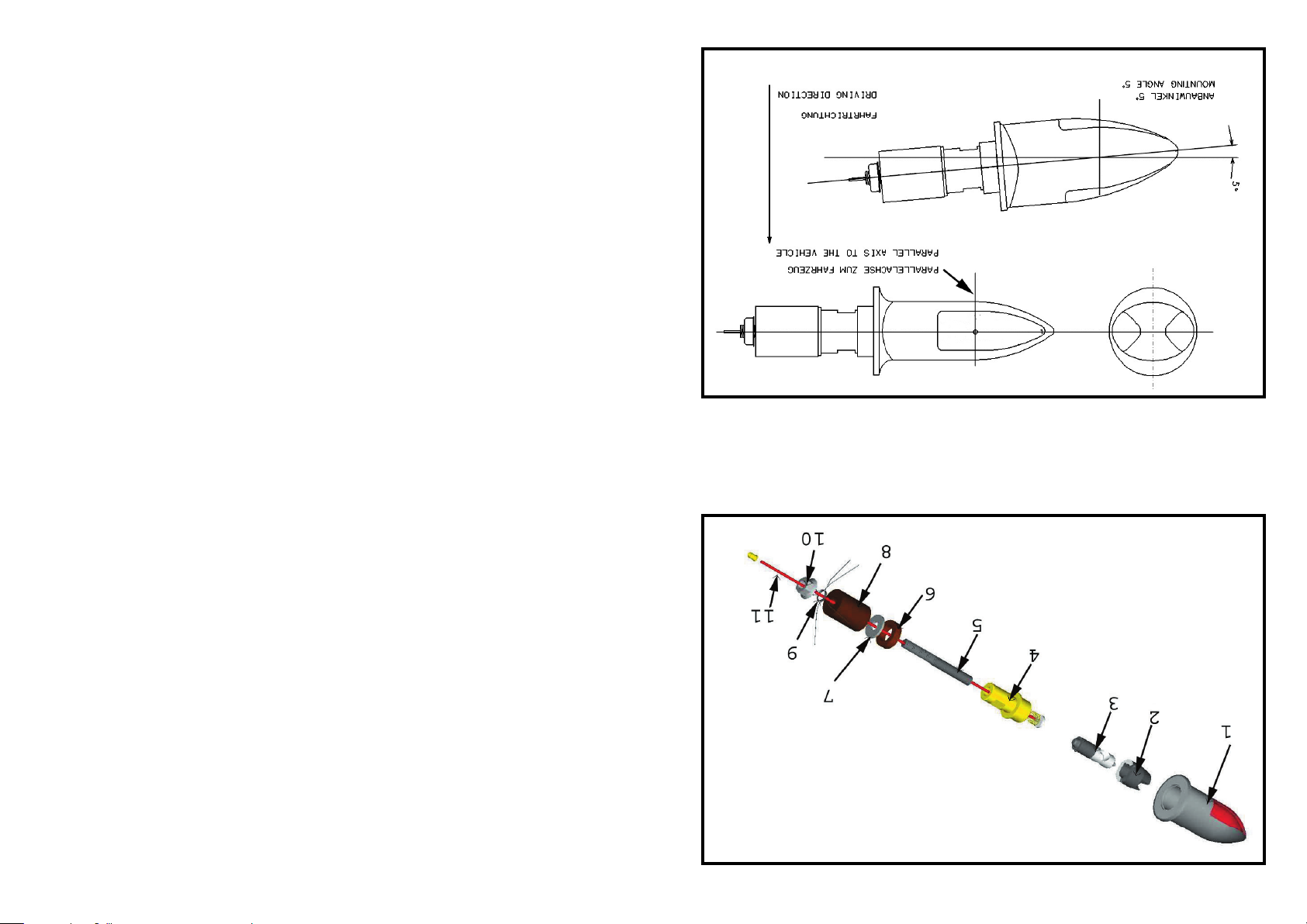
picture 1 1 housing; 2 bulb socket; 3 bulb; 4 adapter w. flat part for wrench; 5 cable tube; 6 rubber spacer; 7 washer; 8 rubber tube; 9 earth contact; 10 nut;
11 connecting cable (positive pole).
step1: Before you drill any hole, please read the instructions of your handle bar manufacturer and/or the regulations of your country. The required mounting
angle of the handle bar indicators is shown on picture 2.
Drill two small 3 mm holes for the cable exit into the handle bar underneath the switch units on each side of the handlebar. Alternatively you can also
drill one 4 mm hole in the middle position of your H/bar. Prepare the holes and make sure that no sharp edges can damage the cables. To prevent
intrusion of water, the drilled holes should face downwards and they should be sealed with silicone after you laid the cables.
step 2: all relevant contact points (incl. inner side of the handle bar) should be cleaned from dirt, rust and grease.
step 3: Choose the correct rubber tube (8) and assemble the parts in the correct order as shown on picture 1. Big rubber tube (8), diameter 20 mm, for 1"
handle bar; middle rubber tube (8), diameter 17 mm, for 7/8" handle bar (mounted); small rubber tube (8), diameter 13 mm, for aluminium handle
bar; mini rubber tube (8), diameter 11,5 mm, for aluminium handle bar.
The cable tube (5), the adapter (4) and the housing (1) must be fixed tightly. Squeeze the fitting rubber tube (8) with the nut (10) until the indicator
can be hardly pushed into the handle bar. Pull the cable (11), with the help of a thin wire, towards the cable exit. Don't pull the cable too hard.
Put the indicator into the handle bar end. The housing of the winker light should be placed close to the handle bar with just a small gap. Turn the indi-
cator clockwise until the indicator is fixed and the amber lens is facing towards the driving direction. Attention: Do a maximum of 3 turns, otherwise
you have to squeeze the rubber tube (8) more tight before you put it into the handle bar. Make sure the throttle grip still turns forward and backward
easily. Now connect the SHIN YO indicator from the right side with the positive cable of the original wire harness (also from the right side). Do the
accordingly on the left side. The earth connection is provided by the contacts (9) and the handle bar. If the handlebar is made of insulating material
like aluminium, you have to lay an extra earth cable. The best position to connect this cable is between the rubber tube (8) and the nut (10). Then
connect it to the earth wire of your vehicle.
step 4: Place your vehicle on a plain ground and face it straight towards a wall. The vehicle and the handle bar must be straight. Don't sit on the vehicle or lift
it on the main stand. Now measure the distance between the ground and the middle of the lens. Right and left side must be the same distance. Mark a
line with the same distance on the wall and turn the indicator until the centre of the illuminated area is in the middle of this line. That means that the
illuminated area under and above the line must have the same size. You have to check this adjustment from time to time. The original front indicators
have to be removed now.
CHANGING THE BULB:
Attention: Never touch the indicator and /or the bulb with pure skin or any material sensitive to heat, while in use or short time after. Wait until it cooled down.
step 1: Turn the indicator anticlockwise unless you can pull it out of the handle bar. Attention: don't pull too hard, you can brake the cable or damage the
indicator. Unscrew the housing (1) from the adapter (4). Use a 10 mm fork wrench. Hold the housing (1) with the hole facing towards you, because
the bulb (3) and the bulb socket (2) are not fixed inside the housing and they can fall out. In case the bulb and the socket get stuck, turn the housing
and tap it on your palm.
step 2: Insert the new bulb (3) without touching the glass cylinder with pure skin. Use a soft tissue. Place the small pins of the bulb to the corresponding groo-
ves of the socket (2). Two sides of the socket are flat and they fit exactly into the corresponding face of the housing (1). Insert the socket with the
bulb and screw on the adapter (4). To mount the winker light follow the steps as described before in this instruction sheet.
BEDIENUNGSANLEITUNG
Lenkerendenblinker
SNAKE EYE
MOUNTING MANUAL
Handle bar indicator
SNAKE EYE
www.shin-yo.de
HOMOLOGATED
Anbauanleitung und Sicherheitshinweise für
SHIN YO Lenkerenden-Blinker 202-550 und 202-552 SNAKE EYE
BITTE SORGFÄLTIG VOR INBETRIEBNAHME LESEN!
WARNUNG:
Lenkerenden-Blinker nur von Fachpersonal einbauen lassen! Eine falsche oder unsachgemäße Befestigung kann zu
Unfällen führen. Vor jedem Fahrtantritt ist die Befestigung und die ordnungsgemäße Funktion der Blinker zu
überprüfen. Nur 12V/21W Halogen Glühlampen mit der Bezeichnung H21W, BAY 9 S verwenden. ACHTUNG,
diese können im Betrieb sehr heiß werden. Deshalb jeglichen Kontakt mit der Haut und sonstigen wärmeempfindlichen Materialien vermeiden. Die Kabel müssen sorg-
fältig verlegt werden, um sicherzustellen, dass sie nicht beim Lenken gequetscht werden können. KURZSCHLUSSGEFAHR!
HINWEISE:
Vor der Installation muss die Zündung ausgeschaltet sein, wir empfehlen die Batterie abzuklemmen. Das Motorrad muss standsicher abgestellt werden. Bei der Montage
müssen die allgemeinen Schutzbestimmungen eingehalten werden (z.B. Schutzkleidung tragen). Diese Blinker sind E– geprüft und müssen deshalb nicht in die
Fahrzeugpapiere eingetragen werden. Wichtig ist es hierbei die Anbauvorschriften genau zu beachten!
Technische Veränderungen der Blinker, der Birnen, der Leitungen und/oder der Steckverbindungen sind nicht zulässig und führen zum Erlöschen jeglicher
Garantieansprüche. Dies gilt auch für daraus entstehende Folgeschäden. Die Blinker sind für eine Spannung zwischen 12 V und 14,8 Volt ausgelegt, bei Überspannung
im Bordnetz (durch defekte Lichtmaschinen, Regler oder Kabelkurzschluss) erlischt jeglicher Garantieanspruch.
ANBAU/ANBAUVORSCHRIFTEN:
Benennung der Bauteile:
Bild 1 1 Gehäuse; 2 Birnenfassung; 3 Birne; 4 Adapter mit Schlüsselfläche; 5 Kabelrohr; 6 Distanzscheibe Gummi; 7 Unterlegscheibe;
8 Klemmgummi; 9 Kontakte (Masse); 10 Mutter; 11 Anschlusskabel (Plus).
Schritt 1 Mit einem Bohrer zwei Löcher für den Kabelausgang in den Lenker bohren z.B. unter den Schalterarmaturen mit 3 mm oder ein Loch in der
Lenkermitte mit 4 mm bohren. Die Bohrungen entgraten, damit die Kabel nicht beschädigt werden können. Nach dem Verlegen sollten die Löcher mit
Silikon abgedichtet werden. Dabei unbedingt die Vorschriften des Lenkerherstellers bzw. TüV beachten. Der zugelassene Anbauwinkel der Blinker ist auf
Bild 2 abgebildet.
Schritt 2 Alle relevanten Kontaktstellen (incl. Lenkerrohr innen) müssen von Schmutz, Fett und Oxidation befreit werden.
Schritt 3 Passendes Klemmgummi (8) heraussuchen und nach Bild 1 zusammenbauen. Reihenfolge der Bauteile beachten. Großer Klemmgummi (8),
Durchmesser 20 mm für 1" Lenker; Mittlerer Klemmgummi (8), Durchmesser 17mm für 7/8" Lenker (vormontiert); Kleiner Klemmgummi (8),
Durchmesser 13 mm für Alu Lenker; Mini Klemmgummi (8), Durchmesser 11,5 mm für Alu Lenker.
Unbedingt darauf achten, dass das Kabelrohr (5), der Adapter mit Schlüsselfläche (4) und das Gehäuse (1) fest miteinander verschraubt sind! Den
passenden Klemmgummi (8) mit der Mutter (10) soweit vorspannen, bis der Blinker nur noch schwer in das Lenkrohr einzuschieben ist. Das Kabel
(11) mit Hilfe eines dünnen Drahtes zum Kabelausgang ziehen, nicht reißen! Den Lenkerendenblinker in das Lenkrohr bis zum Anschlag einschieben
und im Uhrzeigersinn drehen, bis der Blinker festen Sitz hat und ein der Blinkerglas in Fahrtrichtung zeigt. Achtung: Maximal 3 Umdrehungen, anson-
sten muss der Klemmgummi (8) fester vorgespannt werden. Darauf achten, dass sich der Gasgriff auf der rechten Lenkerseite nach der Montage des
Blinkers leicht drehen lässt und beim loslassen sofort zurückdreht.
Nun kann das Blinkerkabel an die jeweilige Plusleitung der Blinker rechts und links angeschlossen werden. Der Massekontakt erfolgt über die Kontakte
(9) und den Lenker. Bei Alulenkern oder gummigelagerten Lenkern muss ein extra Massekabel verlegt werden. Am einfachsten mit einem
Ringanschluss zwischen Klemmgummi (8) und der Mutter (10). Dann an das Massekabel der Originalblinker anschließen.
Schritt 4 Das Motorrad auf einer ebenen Fläche in einem rechten Winkel zu einer Wand aufstellen. Dabei das Motorrad und den Lenker gerade stellen, jedoch
nicht belasten oder auf den Hauptständer stellen. Nun den Abstand zwischen Fahrbahn und Blinkermitte messen (Messwert links u. rechts muss gleich
sein). Nun eine waagerechte Linie auf der Wand mit der gemessenen Höhe markieren. Den Blinker durch drehen so einstellen, dass sich die
Markierung auf der Wand genau in der Mitte des abgestrahlten Lichtbildes befindet. Diese Einstellung muss von Zeit zu Zeit überprüft werden. Die vor-
deren Originalblinker müssen jetzt demontiert werden.
LAMPENWECHSEL:
Schritt 1 Den Blinker gegen den Uhrzeigersinn nur soweit drehen, dass er gerade eben mit Handkraft herausgezogen werden kann. Danach das Gehäuse (1)
vom Adapter (4) abschrauben (Gabelschlüssel 10 mm verwenden). Dabei das Gehäuse (1) mit der Öffnung nach oben halten, da die Halogenbirne
(3) und die Birnenfassung (2) nur lose eingelegt sind. Beide Teile können nun aus dem Gehäuse entnommen werden, dazu das Gehäuse umdrehen
und mit der Öffnung leicht auf die Handfläche klopfen.
Schritt 2 Die neue Halogenbirne so einsetzen, dass die Haltestifte der Birne genau in die Nuten der Birnenfassung passen. Dabei den Glaskörper der Birne am
besten mit einem weichen Tuch und nicht mit den Händen anfassen! Die Birnenfassung (2) ist an zwei Seiten abgeflacht, diese Flächen passen genau
zwischen die Arretierungsflächen im Blinkergehäuse. Die Fassung mit der Birne muss ca. 9,5 mm tief sitzen und das Gewinde des Adapters (4) muss
beim Aufschrauben komplett im Gehäuse verschwinden. Sollte dies nicht möglich sein, muss der Sitz der Birne und der Birnenfassung überprüft werden.
Um den Blinker wieder zu befestigen, folgen sie einfach den am Anfang genannten Schritten.
Bild1/picture1
Bild2/picture2
E-GEPRÜFT
This manual suits for next models
1
Table of contents
Other SHIN YO Motorcycle Accessories manuals


Popular Motorcycle Accessories manuals by other brands


Wunderlich
Wunderlich Krauser 610.092 00 02 Assembling instructions

Ohlins
Ohlins FGR 156 Mounting instructions

Sena
Sena X1S quick start guide

hepco & becker
hepco & becker 501669 00 01 quick start guide

Cardo Systems
Cardo Systems ScalaRider installation instructions

KTM Power Parts
KTM Power Parts 64112992033 Information